1
LBI-38823C
Operator’s Manual
Dual Format PCS
Portable Radio
ericssonz
NOTICE!
This manual covers Ericsson and General Electric products manufactured and sold by Ericsson Inc.
NOTICE!
The software contained in this device is copyrighted
by Ericsson Inc. Unpublished rights are reserved
under the copyright laws of the United States.
This manual is published by Ericsson Inc., without any warranty.
Improvements and changes to this manual necessitated by typographical errors, inaccuracies of current information, or improvements to programs and/or equipment, may be made by Ericsson Inc.,
at any time and without notice. Such changes will be incorporated
into new editions of this manual. No part of this manual may be
reproduced or transmitted in any form or by any means, electronic or
mechanical, including photocopying and recording, for any purpose,
without the express written permission of Ericsson Inc.
Copyright © September 1992, Ericsson GE Mobile Communications Inc.
2
TABLE OF CONTENTS
INTRODUCTION . . . . . . . . . . . . . . . .
DESCRIPTION . . . . . . . . . . . . . . . . .
CONTROLS . . . . . . . . . . . . . . .
INDICATORS . . . . . . . . . . . . . . .
ALERT TONES . . . . . . . . . . . . . .
ERROR MESSAGES . . . . . . . . .
INTRINSICALLY SAFE USAGE . . . . . .
OPTIONS AND ACCESSORIES . . . . . .
BATTERY PACKS . . . . . . . . . . . . .
BATTERY PACKS (FM APPROVED)
.
.
.
.
.
.
.
.
.
.
5
8
8
11
14
16
16
17
19
19
INSTALLING THE BATTERY PACK . . .
19
REMOVING THE BATTERY PACK . . . .
19
CHARGING THE BATTERY PACKS . . .
21
RECHARGEABLE BATTERY PACK DISPOSAL
SWIVEL MOUNT REMOVAL
AND REPLACEMENT . . . . . . . . . . . . .
22
OPERATING TIPS . . . . . . . . . . . . . . .
24
OPERATING PROCEDURES . . . . . . . . .
24
NICKEL-CADMIUM BATTERY WARRANTY . .
26
EDACS OPERATION . . . . . . . . . . . . .
27
RECEIVING A MESSAGE . . . . . . . .
27
SENDING A MESSAGE . . . . . . . . .
28
SQUELCH ADJUSTMENT . . . . . . . .
28
SENDING A SPECIAL CALL . . . . . . .
29
3
2
TABLE OF CONTENTS (Continued)
SCAN OPERATION . . . . . . . . . . . .
36
DYNAMIC REGROUPING (Optional) . . .
37
DTMF OVERDIAL . . . . . . . . . . . . .
37
HOME/EMERGENCY KEY DEFINITION .
38
EMERGENCY OPERATION (Optional) . .
38
HOME . . . . . . . . . . . . . . . . . . .
39
KEYPAD LOCK (SYSTEM Model Only) . .
GE-MARC OPERATION . . . . . . . . . . . . .
RECEIVING A MESSAGE . . . . . . . . .
39
41
41
SENDING A MESSAGE . . . . . . . . . .
42
SENDING A SPECIAL CALL . . . . . . . .
43
WIDE AREA SYSTEM SCAN . . . . . . .
52
DIRECT MODE . . . . . . . . . . . . . .
52
SENDING A MESSAGE . . . . . . . . . .
53
SENDING A MANUALLY ENTERED
INTERCONNECT CALL . . . . . . . . . .
54
SCAN OPERATION . . . . . . . . . . . .
CONVENTIONAL MODE OPERATION . . . . .
RECEIVING A MESSAGE . . . . . . . . .
54
57
57
SENDING A MESSAGE . . . . . . . . . .
58
SQUELCH ADJUSTMENT . . . . . . . . .
58
SENDING A MANUALLY ENTERED
INTERCONNECT CALL . . . . . . . . . .
58
SCAN OPERATION . . . . . . . . . . . .
WARRANTY . . . . . . . . . . . . . . . . . . .
59
63
4
INTRODUCTION
The Dual Format PCS Portable Radio provides reliable
trunked communication in the 800 MHz band. Advanced Dual
Format technology allows the radio to operate within the
EDACS Trunked system and the GE-MARC Trunked system.
The radio will also operate in a Conventional system.
The radio is housed in a molded Lexan front and an aluminum
rear casting. The unit is lightweight and easy to carry. A backlit
numeric display provides clear visibility for night-time operation. There are two models available, a 3-button Scan and a
12-button System. Both models are capable of Dual Format
operation.
This manual provides instructions for operating both the Scan
and the System model radio in either of the 3 systems (EDACS,
GE-MARC and Conventional). A separate section is provided
for each System (EDACS, GE-MARC and Conventional), with
a complete set of instructions for operating the radio within that
system. The DESCRIPTION section which follows and the
Battery information at the back of the manual, is applicable to
all users.
NOTE
This radio allows the operator to switch between an EDACS
system, a GE-MARC system and a Conventional system. Special
attention should be given to the system selected and the operating
characteristics of the PCS radio working within that system.
5
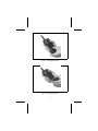
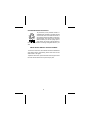
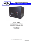
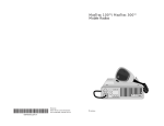
Figure 1 - Dual Format PCS Radio (SCAN Model)
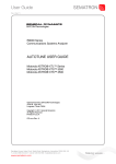
6
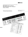
Figure 2 - Dual Format PCS Radio (SYSTEM Model)
7
DESCRIPTION
CONTROLS
ON/OFF
SWITCH
The ON/OFF Switch is located on the battery pack.
Sliding this switch up to the ON position will supply
power to the radio from the battery pack. The radio
can be programmed to beep once after power is
applied, indicating it is ready for use.
PTT BUTTON
Push-To-Talk
Pressing the PTT button (located on the side of the
radio) will key the radio’s transmitter and perform
the necessary steps to acquire a communication
channel.
SHIFT/CLR
All alternate key functions are accessed by pressing the SHIFT/CLR button and then pressing the
desired function key.
Trunked - Pressing the SHIFT/CLR button twice
("double click") will invoke the CLEAR function
which is used to exit the Special Call mode and
return to the normal System/Group display.
Conventional - Pressing the SHIFT/CLR button
twice ("double click") will enable MONITORING the
channel for activity by unsquelching the receiver.
All transmissions will be heard, even if Channel
Guard protected.
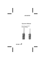
8
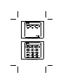
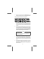
Figure 3 - SCAN Model Keypad
Figure 4 - SYSTEM Model Keypad
9
S
The Select buttons are two momentary (auto ramping) switches used to increment or decrement the
current Group/Channel selection. Pressing the
shift button and then the S buttons will increment or
decrement the System selection. The Select buttons are also used to increment or decrement the
Special Call selection while in the Special Call
mode.
V
The Volume buttons are two momentary (auto
ramping switches) used to increment or decrement
the volume level from the speaker. A tone sounds
each time the Volume buttons are pressed, except
when a call is in process.
HOME/E
The HOME/Emergency key is used to automatically select a desired Group and/or System by
pressing and holding the key for a programmed
duration. The HOME/Emergency key is also used
to declare emergencies by pressing and holding the
key for a preprogrammed duration. Emergency
messages may only be issued on EDACS systems.
SPC
Pressing the SPC (Special) key will put the radio in
the Special Call mode. From the Special Call mode
the radio is able to make individual and interconnect
calls. This key is active with trunked systems only.
SCAN-A/D
The SCAN-Add/Delete key is used to enable the
Scan mode and to add or delete Groups/Channels
to the scan list.
STO
The STOre key in combination with the SHIFT/CLR
button is used to store individual call numbers and
interconnect calls. This key is available on System
Model radios and is active with trunked systems
only.
10
LOCK
The LOCK key in combination with the SHIFT/CLR
key is used to lock the key pad. All buttons and keys
will be locked except the VOLUME, PTT, HOME/E,
SHIFT/CLR and the LOCK (shifted 0). This key is
available on System Model radios only.
RCL
The RCL (Recall) key (shifted #) can be used to
recall manually entered individual and interconnect
calls in the EDACS and GE-MARC systems. This
key is available on System Model radios and is
active with trunked systems only.
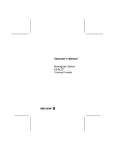
INDICATORS
The 4-digit LIQUID CRYSTAL DISPLAY (LCD) uses the two
digits on the left side to indicate the System number and the
two digits on the right side to indicate the Group/Channel
number. In addition there are 9 status indicators that are
described on the following pages.
The LCD backlighting can be programmed to turn on anytime
a button or key is pressed. It will remain on for a programmable
length of time after the button or key is released. Backlighting
is programmed on a per Group/Channel basis or it may be
programmed to remain off at all times. Each radio that is
programmed with backlighting may also be programmed to
remain on or off when the PTT bar is pressed.
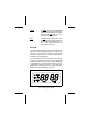
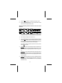
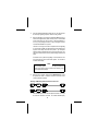
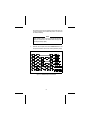
Figure 5 - Dual Format PCS Display
11
System And Group/Channel Indicators
The SYStem display indicates the number of the
current EDACS, GE-MARC or Conventional system selected.
The GRP (Group) display indicates the number of
the current Group in an EDACS or GE-MARC System. The GRP icon is surpressed while operating
from a Conventional System, but the field is still
used to display the Channel selected.
Status Indicators
TX
The Transmitter flag is on when the radio is transmitting.
BSY
The Channel Busy flag is on when the radio receives a call or when a conventional channel is in
use. The flag is also on when transmitting on a
trunked channel. This flag flashes when a call is
queued on a trunked system.
BT
The Battery flag is on when the battery power is
low and needs charging.
NO
EDACS - The NO Service flag is used in conjunction
with the Service flag to indicate no service. The
illumination of both the NO and the SV flag indicates
a no service condition.
GE-MARC - The NO flag is used in conjunction with
the Service flag to indicate an unsuccessful attempt
to access a GE-MARC System. The illumination of
both the NO and the SV flag indicates a failed
attempt to access a GE-MARC system.
CONVENTIONAL - The NO flag remains off at all
times while operating in Conventional mode.
12
SV
EDACS - The Service flag is normally on to indicate
service. If a no service condition occurs the SV flag
and the No Service flag will be illuminated.
GE-MARC - The Service flag is normally off. If an
unsuccessful attempt is made to access a GEMARC System, both the SV and the NO flags will
turn on.
CONVENTIONAL - The Service flag remains off at
all times while operating in Conventional mode.
SCN
The Scan flag is on when Scan is activated.
S
The "S" flag is used to indicate two conditions. The
"S" flag is used in conjunction with the "PC" flag to
indicate the radio is in the Special Call mode. The
"S" flag is also used to indicate when a trunked
group is scan enabled.
PC
The "PC" flag is illuminated with the "S" flag to
indicate the radio is in the Special Call mode. When
the "PC" flag is illuminated without the "S" flag, the
radio is in the Program mode.
1
The "1" flag is used only for radio logical ID display.
When receiving a call, the most significant digit (0
or 1) of the originating radio’s ID will be displayed
by the "1" flag. When on, the ID of the originating
radio begins with a 1.
13
ALERT TONES
The Dual Format PCS radio generates a number of alert tones to
indicate various events. The following section describes the alert tones for
the Dual Format PCS radio.
Standard Tones
Power-Up
If programmed, a tone will sound on power-up after the radio passes
the self-test.
Low Battery
A low pitch tone will sound every 130 seconds when the battery is low
and needs charging.
Carrier Control Timer
The Carrier Control Timer (CCT) alert is a pulsed tone signal that
sounds whenever the PTT button is continuously pressed for a preprogrammed length of time. After nine seconds of pulsing the transmitter shuts
down and communications is interrupted. To maintain communications,
release and re-key the PTT switch. This resets the timer and turns the
transmitter back on. The CCT is a built-in precaution against inadvertent use
of the system.
Tones For Trunked Operation Only
Call Originate
EDACS - If programmed, a short tone is sounded whenever the
Push-To-Talk (PTT) button is keyed and the radio has acquired a
channel. This tone indicates the user may proceed to talk.
GE-MARC - If programmed, a three tone alert is sounded whenever
the Push-To-Talk (PTT) button is keyed and the radio has acquired a
channel. This tone indicates the user may proceed to talk.
14
Call Received
If programmed, a single alert tone sounds when a group call is received
and a two tone alert (one high followed by one low tone) is sounded for an
individual call.
Call Queued (EDACS Only)
If one short, high pitched tone sounds after the transmitter is keyed,
this indicates that the system has placed the request in a queue. This tone
sounds at both the transmitting unit and the receiving unit(s), indicating to the
user on the receiving end that they will receive a call shortly. If the PTT is
unkeyed while in the queue, the radio will autokey (automatically key the PTT)
when a channel becomes available (see AUTOKEY below).
Autokey (EDACS Only)
When the PTT is keyed to place a call on the system, but the PTT is
released before getting to the channel (e.g. a queued call), the radio automatically keys on the channel when it gets the assignment. The radio
generates a long beep and holds the transmitter keyed for two seconds.
Pressing the PTT button keeps the channel and sends the message before
this two second time-out has expired.
System Busy
EDACS - If you key the PTT bar and hear three short, medium pitched
tones, this indicates that the receiving party is already engaged in
another call or the system is busy and its queue is full. You must rekey
later to access the system.
GE-MARC - If you key the PTT bar and hear a low frequency tone for
1 second this indicates all channels are busy.
Call Denied (EDACS Only)
A single low pitch beep will sound when the PTT switch is keyed and
the request is denied by the system. This happens if the unit is an invalid
user or if the unit is requesting an unavailable service.
15
Out Of Range/System Inoperative
EDACS - A single low pitched tone will sound immediately after the
PTT switch is keyed indicating the radio is out of range of the repeater.
The radio tries to place the call for a short period (3 seconds) after the
initial attempt. The radio generates a second low pitched tone when
it gives up trying to place the call. The system is off the air or the radio
needs servicing when the radio is within calling range, and these tones
are heard.
GE-MARC - Five beeps will sound shortly after the PTT switch is keyed
when the radio is out of range of the repeater or the radio is inoperative.
If the "Call Retry is active, the radio will try the channel at twenty second
intervals for five minutes.
ERROR MESSAGES
E3 - If at anytime the Synthesizer is unable to load and lock on
the channel properly an "E3" message will be displayed in the
System field and the Group/Channel field will be blanked. If the
"E3" message is displayed on all systems, the radio has failed
or has not been programmed properly. The radio’s buttons and
keys will still operate with an "E3" message displayed.
E9 - "E9" message indicates the Personality has not been
programmed into the radio.
INTRINSICALLY SAFE USAGE
Selected portable radios with appropriate factory installed F4 Options are
certified as Intrinsically Safe by the Factory Mutual Research Corporation.
Intrinsically Safe approval includes Class I, II, III, Division 1 hazardous
locations in the presence of Groups C, D, E, F and G atmospheres.
Non-Incendive approval includes Class I, Division 2 hazardous locations in
the presence of Groups A, B, C and D atmospheres.
Hazardous locations are defined in the National Electrical Code. Useful
standards NFPA 437A and NFPA 437M for the classifications of hazardous
areas can be ordered from the National Fire Protection Association,
Batterymarch Park, Quincy, MA 02269.
16
OPTIONS AND ACCESSORIES
OPTION #
PCAC1C
PCAC1J
PCAE1X
PCZM1A*
PCHC1C*
PCHC1D*
PCHCSS*
PCHCST
PCHCSU
PCHCSV
PCNC3L*
PCPA1J*
PCPA1K*
PCPA1L
PCPS1K
CH1SS1*
CH1SS2
CH1RS1*
CH1RS2
CH6SS1
CH6SS2
CH6RS1
CH6RS2
DESCRIPTION
Earphone UDC Connector Only (FM APPROVED)
Earphone Without UDC Connector (FM APPROVED)
Speaker MIC (FM APPROVED)
Earphone With UDC Connector (FM APPROVED)
Belt Clip (FM APPROVED)
Swivel Plate (FM APPROVED)
Case With Top Short Battery (FM APPROVED)
Case With Strap Short Battery (FM APPROVED)
Case With Top Long Battery (FM APPROVED)
Case With Strap Long Battery (FM APPROVED)
Antenna Whip 806-870 MHz
High Capacity Battery Pack
Extra High Capacity Battery Pack
Extra High Capacity Battery Pack (FM APPROVED)
Mobile Charger (Sleeve)
Desk Charger 50/60Hz, 120V, 14HR
Desk Charger 50/60Hz, 230V, 14HR
Rapid Desk Charger 50/60Hz, 120V, 1HR
Rapid Desk Charger 50/60Hz, 230V, 1HR
Multicharger 50/60Hz, 120V, 14HR
Multicharger 50/60Hz, 230V, 14HR
Rapid Multicharger 50/60Hz, 120V, 1HR
Rapid Multicharger 50/60Hz, 230V, 1HR
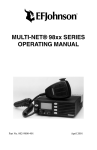
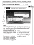
* Pictured on page 18.
17
Figure 6 - Options And Accessories
18
BATTERY PACKS
The following battery pack are available for use with the Dual Format
PCS radio:
PCPA1J
(19A705293P1)
Rechargeable Battery Pack, High Capacity
PCPA1K
(19A705293P2)
Rechargeable Battery Pack, Extra High Capacity
BATTERY PACKS (FM APPROVED)
Only battery packs identified with a green latch shall be used
with a portable radio that is rated and labeled as Factory Mutual
Intrinsically Safe. Use of nonspecified battery packs voids
Factory Mutual approval. The following battery pack option is
approved for use in intrinsically safe radios.
PCPA1L
Rechargeable Battery Pack
Extra High Capacity (Tall Case)
CAUTION
Battery packs used with the PCS radio must be supplied by
Ericsson Inc.
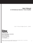
INSTALLING THE BATTERY PACK
1.
Ensure the ON/OFF switch on the battery pack is in the off position.
2.
Hold the radio and battery pack with the back of them facing you. See
Figure 7.
3.
Align the grooves on the top of the battery pack with the grooves on
the bottom of the radio.
4.
Slide the battery pack fully into the radio until the battery release latch
clicks into place.
19
REMOVING THE BATTERY PACK
1.
Ensure the ON/OFF switch on the battery pack is in the off position.
2.
Press down on the battery release latch and slide the battery pack out
in the direction of the release latch. See Figure 8.
CHARGING THE BATTERY PACKS
New batteries or batteries that have been stored for a long period of
time, should be fully charged before placing into service. When the battery
pack requires charging the "BT" indicator in the LCD will turn on and the radio
will sound a low pitch tone every 130 seconds.
Rechargeable batteries in some applications can develop a condition
of reduced capacity, sometimes called "Memory Effect". This condition may
occur when:
1.
The battery is continuously overcharged for long periods of time.
2.
A regularly performed duty cycle allows the battery to expend only a
limited portion of its capacity.
If the rechargeable battery is only sparingly or seldom used and is left
on continuous charge for one or two months at a time, it could experience
reduced capacity. This would severely reduce the life of the battery between
charges.
The most common method of producing this limited capacity is regularly performing short duty cycles; when the battery is operated so that only
a portion (<50%) of its capacity is expended. This type of operation can cause
the battery to become temporarily inactive and show severe decrease in the
ability to deliver at full rated capacity.
Any rechargeable battery showing signs of reduced capacity, should
be taken to a qualified Service Technician to be carefully checked before
being returned under warranty or scrapped.
20
Figure 7 - Installing the Battery Pack
Figure 8 - Removing the Battery Pack
21
RECHARGEABLE BATTERY PACK DISPOSAL
The product that you have purchased contains a rechargeable battery. The battery is recyclable. At the end
of its useful life, under various state and local laws, it
may be illegal to dispose of this battery into the municipal waste stream. Check with your local solid waste
officials for details in your area for recycling options or
proper disposal. Call Toll Free 1-800-822-9362 for information and/or procedures for returning rechargeable batteries in your
state.
SWIVEL MOUNT REMOVAL AND REPLACEMENT
To remove the swivel mount, slide a flat blade screwdriver underneath the
spring retainer and twist. While twisting, slide the swivel mount out from
under the holder. See Figure 9.
To replace the swivel mount, place the end of the swivel in the grooves in the
back of the radio and slide the mount up until it snaps in place.
22
Figure 9 - Swivel Mount Removal And Replacement
23
OPERATING TIPS
The following conditions tend to reduce the effective range of two-way
radios and should be avoided whenever possible.
• Operating the radio in low terrain areas or while under power lines or
bridges.
• Operating the radio inside of a vehicle or inside metal or steel framed
building unless using an outside antenna.
• Obstructions such as mountains or buildings between the person sending
and the person receiving the message.
In areas where transmission or reception is poor, some improvements
may be obtained by insuring that the antenna is vertical. Moving a few yards
in another direction or moving to a higher elevation may also improve
communication.
OPERATING PROCEDURES
Two-way FM radio systems must be operated in accordance with
the rules and regulations of the Federal Communications Commission
(FCC). As an operator of two-way radio equipment, you must be
thoroughly familiar with the rules that apply to your particular type of
radio operation. Following these rules will help eliminate confusion and
will assure the most efficient use of existing radio channels. This will
provide a smooth operating radio network.
When using two-way radios, remember the following rules:
1.
It is a violation of FCC rules to interrupt any distress or emergency
messages. As the radio operates in much the same way as a telephone "party line", always listen and/or observe the absence of the
"BSY" flag to make sure that the line is clear. If someone is sending
an emergency message, such as reporting a fire or asking for help in
an accident; KEEP OFF THE AIR! Emergency calls have priority over
all other messages.
2.
Use of profane or obscene language is prohibited by federal law.
24
3.
It is against the law to send false call letters and false distress or
emergency messages.
4.
The FCC requires that conversations be kept brief and confined to
business. To save time, use coded messages whenever possible.
5.
Using the radio to send personal messages (except in an emergency)
is a violation of FCC rules. Send only those messages that are
essential for the operation of your business.
6.
It is against federal law to repeat or otherwise make known anything
overheard on the radio. Conversations between others sharing your
channel must be regarded as confidential.
25
NICKEL-CADMIUM BATTERY WARRANTY
A.
B.
C.
D.
E.
Ericsson Inc. (hereinafter "Seller") warrants to the original purchaser for use (hereinafter "Buyer") that nickel-cadmium batteries
supplied by Seller shall be free from defects in material and
workmanship, and shall conform to its published specifications for
a period of twelve (12) months from the date of purchase.
For purposes of this warranty, batteries shall be deemed defective
if (1) the battery capacity is less than 80% of rated capacity, or (2)
the battery develops leakage.
If any battery fails to meet the foregoing warranty, Seller shall
correct the failure by issuing a replacement battery upon receipt
of the defective battery at an Authorized Service Center (ASC)..
To obtain the name and address of a ASC, ask your salesperson,
consult the Yellow Pages, or call the number printed at the bottom
of this page.
Replacement batteries shall be warranted only for the remaining
unexpired warranty period of the original battery. This warranty
becomes void if:
(1) The battery has been subjected to any kind of misuse,
detrimental exposure, or has been involved in an accident.
(2) The battery is used in equipment or service other than the
radio equipment for which it is specified.
The preceding paragraphs set forth the exclusive remedies for
claims (except as to title) based upon defects in or non-conformity
of any battery, whether the claim is in contract, warranty, tort
(including negligence), strict liability or otherwise, and however
instituted. Upon the expiration of the warranty period, all such
liability shall terminate. The foregoing warranties are exclusive
and in lieu of all other warranties, whether oral, written, expressed,
implied or statutory. NO IMPLIED OR STATUTORY WARRANTIES OF MERCHANTABILITY OR FITNESS FOR PARTICULAR
PURPOSE SHALL APPLY. IN NO EVENT SHALL THE COMPANY BE LIABLE FOR ANY INCIDENTAL, CONSEQUENTIAL,
SPECIAL, INDIRECT OR EXEMPLARY DAMAGES.
This warranty applies only within the United States.
1-800-528-7711 (Outside USA, 804-528-7711).
ECX-841C
26
EDACS OPERATION
RECEIVING A MESSAGE
1.
Turn the radio on by sliding the ON/OFF switch on the battery pack, to
the ON position. A yellow area will be visible on the battery. After the
radio has passed the power-up self test an optional tone will sound and
the current System and Group will be displayed. If the unit does not
pass the test, an error message will be displayed (see ERROR
MESSAGES section) or the display will be blank.
2.
Press the SHIFT/CLR button and then use the SELECT buttons s or
t to select an EDACS system. The SYStem display will indicate the
current System selected.
3.
Use the SELECT buttons s or t to select the desired Group. The GRP
display will indicate the current Group selected. The radio is now ready
to receive messages.
4.
INDIVIDUAL CALL - If an individual call (call directed only to your radio)
is received, the radio unsquelches on the assigned channel and the
"BSY" flag lights. If programmed on, the individual call received tones
(one high followed by one low) will sound and the originator’s ID or just
"id" (dependent upon programming) is displayed in the GRP and SYS
fields.
GROUP CALL - When the radio receives a group call, it unsquelches
on the assigned channel and lights the "BSY" flag. If programmed on,
the group call received tone (single tone) will sound. The radio can
also be programmed to display the Group name orginators ID in the
GRP and SYS fields.
INTERCONNECT CALL - If an interconnect call (telephone call directed to your radio) is received, the radio unsquelches on the assigned
channel and the "BSY" flag turns on. If programmed on, the interconnect call received tones (one high followed by one low) will sound. A
"ph" will be displayed in the GRP field.
NOTE
The optional call received tones are programmed off by default.
27
5.
Using the VOLUME buttons, adjust the volume as necessary.
SENDING A MESSAGE
1.
Turn the radio on and set the desired System and Group as described
under RECEIVE A MESSAGE steps 1-3.
2.
Observe the display for the presence of the "SV" flag for service and
the absence of the "BSY" indicator to ensure that no one is transmitting
on the selected Group.
3.
Press and hold the PTT bar. The radio will perform the necessary
signalling required to obtain a communication channel. If the signalling
is unsuccessful, the radio will sound the appropriate alert tone(s).
4.
When the channel has been acquired, the "TX" and "BSY" flags are
illuminated and if programmed, the Call Originate tone will sound.
5.
Hold the radio about 3 inches from your mouth and speak as you would
normally into the microphone.
6.
Release the PTT bar when the transmission is complete and listen for
any reply.
SQUELCH ADJUSTMENT
In normal operation the squelch is automatically set by the radio and
does not need adjusting. If it becomes necessary to adjust the squelch, the
squelch may be adjusted using the following procedure:
NOTE
The radio must be on a Conventional System or an EDACS working
Channel (i.e. receiving a voice call) to adjust the squelch. It is
recommended to adjust squelch from a Conventional System.
28
1.
Press and hold the SHFT/CLR button.
2.
Use the VOLUME s or t buttons to adjust the squelch. Pressing the
VOLUME s will open the squelch and pressing the VOLUME t will
close the squelch.
SENDING A SPECIAL CALL
SCAN Model Radio
1.
Press the SPC key to put the radio into Special Call mode and provide
access to a preprogrammed special call list. Each selection from the
list is preprogrammed with either an individual number or an interconnect number. The SYStem field will display "SP" and the GRP (Group)
field will display the current selection number from the special call list.
The "S" and "PC" icons will also be illuminated while in the Special
Call mode.
2.
Press the SELECT s or t buttons to increment or decrement through
the special call list.
NOTE
To display the last four digits of the individual or interconnect
number currently selected, press and hold the SHFT/CLR button
and then press the SPC key.
3.
Individual - Once the desired individual special call number is displayed
in the GRP (Group) field, press and hold the PTT to initiate the call.
The radio performs the necessary signalling required to obtain a
working channel.
Interconnect - Once the desired interconnect special call number is
displayed in the GRP (Group) field, press and release the PTT to initiate
the call. The radio performs the necessary signalling required to obtain
a working channel.
4.
Individual - When the signalling is successfully completed the"TX" and
"BSY" flags turn on and the Call Originate tone sounds. Speak directly
into the microphone. Release the PTT bar as soon as you stop talking
and wait for a reply.
29
Interconnect - When the signalling is successfully completed the
"BSY" flag turns on and the proper DTMF tones will be sent and heard
at the speaker. When someone answers, press the PTT bar and speak
directly into the microphone. Release the PTT bar as soon as you stop
talking. Messages cannot be received when the PTT bar is pressed.
If the signalling is unsuccessful, the radio will remain in the the Special
Call Mode and sound the appropriate alert tone(s).
5.
When the call is complete, double click the SHIFT/CLR button to exit
the Special Call mode and return to the normal System/Group display.
SYSTEM Model Radio
The System radio may also initiate a call from the Special Call selection
as described in the SCAN Model Radio section. In addition, the System radio
is capable of the following from the Special Call Mode:
• Storing and/or recalling up to 10 individual and 10 interconnect numbers
in 2 separate storage locations. These numbers are manually entered
from the keypad.
• Initiating individual and interconnect calls that are manually entered from
the keypad.
Each of these features are discussed in detail in the following sections.
Sending A Manually Entered Individual Call
1.
Press the SPC key to put the radio into Special Call mode. The
SYStem field will display "SP" and the GRP (Group) field will display
the last accessed Special call number from the preprogrammed Special Call selection. The "S" and "PC" icons will also be illuminated
while in the Special Call Mode.
2.
Enter the ID number of the radio to be called. The first digit entered
will cause the System field and the 10’s digit in the Group field to blank.
The last digit entered will always be displayed in the 1’s digit of the
Group display. Any previously entered digits will scroll left. Only four
30
characters will be visible at a time with the leading character scrolling
off the display upon each new key entry.
NOTE
To recall the last individual number entered manually from the
key pad, press and hold the SHFT/CLR button and then press
the RCL key.
3.
Press and hold the PTT bar to initiate the call. The radio performs the
necessary signalling required to obtain a working channel.
4.
When the signalling is successfully completed the "TX" and "BSY"
flags turn on and the Call Originate tone sounds. Speak directly into
the microphone. Release the PTT bar as soon as you stop talking and
wait for a reply. Messages cannot be received when the PTT bar is
pressed.
If the signalling is unsuccessful, the radio will remain in the the Special
Call Mode and sound the appropriate alert tone(s).
5.
When the call is complete, double click the SHIFT/CLR button to exit
the Special Call mode and return to the normal System/Group display.
31
Sending A Manually Entered Interconnect Call
1.
Press the SPC key to put the radio into Special Call mode. The
SYStem field will display "SP" and the GRP (Group) field will display
the last accessed call number from the preprogrammed Special Call
selection. The "S" "PC" icons will also be illuminated while in the
Special Call Mode.
2.
Enter the telephone number to be called. The first digit entered will
cause the System field and the 10’s digit in the Group field to blank.
The last digit entered will always be displayed in the 1’s digit of the
Group field. Any previously entered digits will scroll left. Only four
characters will be visible at a time with the leading character scrolling
off the display upon each new key entry.
NOTE
To recall the last interconnect number entered manually from the
key pad, press and hold the SHFT/CLR button and then press
the RCL key.
3.
Complete the telephone entry by pressing the * key. The * key indicates
the digits are for an interconnect call. This will not be displayed but a
tone will sound.
4.
Press and release the PTT bar to initiate the call. The radio performs
the necessary signalling required to obtain a working channel. When
the signalling is successfully completed the "BSY" flag lights and the
proper DTMF tones will be sent and heard at the speaker.
If the interconnect signalling is unsuccessful, the radio will remain in
the the Special Call Mode and sound the appropriate alert tone(s).
5.
When someone answers, press the PTT bar and speak directly into
the microphone. Release the PTT bar as soon as you stop talking.
Messages cannot be received when the PTT bar is pressed.
32
6.
When the call is complete, double click the SHIFT/CLR button to exit
the Special Call mode and return to the normal system/group display.
Storing Individual And Interconnect Numbers
1.
Press the SPC key to put the radio into Special Call mode. The
SYStem field will display "SP" and the GRP (Group) field will display
the last accessed call number from the preprogrammed Special Call
list. The "S" and "PC" icons will also be illuminated while in the Special
Call mode.
2.
Enter the ID number or telephone number of the radio to be stored.
The first digit entered will cause System display and the 10’s digit in
the Group field to blank. The last digit entered will always be displayed
in the 1’s digit of the Group field. Any previously entered digits will
scroll left. Only four characters will be visible at a time with the leading
character scrolling off the display upon each new key entry.
NOTE
To recall the last individual or interconnect number entered
manually from the key pad, press and hold the SHFT/CLR button
and then press the RCL key.
3.
Complete the entry by pressing the # key for individual numbers and
the * key for telephone interconnect numbers. The # key indicates the
digits entered are for an individual call and * key indicates the digits
are for an interconnect call. They will not be displayed but a tone will
sound.
4.
Enter a digit between 0 and 9 to select a storage location. The storage
location will not be displayed, but a tone will sound. There are 10
storage locations for individual numbers and 10 storage locations for
interconnect numbers.
33
5.
Press the STO key (shifted *) to complete the storage procedure.
6.
Double click the SHIFT/CLR button to exit the Special Call mode and
return to the normal System/Group display.
Recalling Manually Stored Individual And Interconnect
Numbers
1.
Press the # key to recall the individual call list or the * key to specify
the interconnect call list. The screen will blank and a tone will sound.
2.
Enter the desired storage location number (0-9).
3.
Press the RCL (shifted #) key and the radio will switch to the Special
Call mode. If the number is from the individual call list the ID number
will be displayed. If the number is from the interconnect call list, the
last four digits of the telephone number will be displayed.
If the memory location is blank the radio will sound a low pitch tone
after the RCL is pressed.
4.
Individual - Once the desired individual call number is displayed in the
GRP (Group) field, press and hold the PTT to initiate the call. The radio
performs the necessary signalling required to obtain a working channel.
Interconnect - Once the desired interconnect special call number is
displayed in the GRP (Group) field, press and release the PTT to initiate
the call. The radio performs the necessary signalling required to obtain
a working channel.
5.
Individual - When the signalling is successfully completed the"TX" and
"BSY" flags turn on and the Call Originate tone sounds. Speak directly
into the microphone. Release the PTT bar as soon as you stop talking
and wait for a reply.
34
Interconnect - When the signalling is successfully completed the
"BSY" flag turns on and the proper DTMF tones will be sent and heard
at the speaker. When someone answers, press the PTT bar and speak
directly into the microphone. Release the PTT bar as soon as you stop
talking. Messages cannot be received when the PTT bar is pressed.
If the signalling is unsuccessful, the radio will remain in the the Special
Call Mode and sound the appropriate alert tone(s).
6.
When the call is complete, double click the SHIFT/CLR button to exit
the Special Call mode and return to the normal System/Group display.
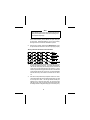
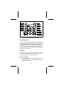
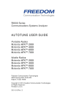
Figure 10 - EDACS Special Call Flowchart
35
SCAN OPERATION
Enable/Disable SCAN
To enable Group scanning, press and release the SCAN key. The
"SCN" icon will illuminate to indicate scan is active. When scan is on, press
and release the SCAN key to disable scan operation. The "SCN" icon will
be extinguished when scan is turned off.
Add/Delete Groups
Groups can be added or deleted from the scan list as necessary. To
add Groups to the scan list:
1.
Select the desired Group to be added. If the current group is already
included in the scan list, the "S" icon will be illuminated.
2.
To add the group to the scan list, press the SHIFT/CLR key and then
press the SCAN key. The "S" icon will illuminate and the group will be
included.
NOTE
Scan must be disabled to add a Group to the scan list.
To delete Groups from the scan list:
1.
Select the desired Group to be deleted. If the current group is already
included in the scan list, the "S" icon will be illuminated.
2.
To delete the group from the scan list, press the SHIFT/CLR button
and then press the SCAN key. The "S" icon will turn off and the group
will be removed from the scan list.
Wide Area And Priority System Scanning (Optional)
Dual Format PCS radios operating within an EDACS system may
be programmed for Wide Area Scan operation for multi-site applications.
Upon the loss of the currently selected system’s control channel, radios may
be programmed to automatically scan other systems. If a new control
36
channel is found, the radio will switch to the new system and sound an alert
tone. Group selection may change upon switching to the new system.
The radio may also be programmed for priority wide area system scan.
A priority system may be assigned to each system programmed into the radio.
Radios programmed in this manner will scan the priority trunked system’s
control channel once every one, two, three or four minutes (programmable).
This priority scan timer is reset each time the PTT bar is pressed.
DYNAMIC REGROUPING (Optional)
Dynamic Regrouping is a feature which allows the System Manager to
dynamically program new groups into selected radios. Upon development
of the regrouping plan, the site controller sends each radio the regroup plan
number, "group position", and activate/deactivate commands. When the
radio is regrouped, it will alert the user and the Group field will will display the
regroup number "nn" (nn = 01-08).
NOTE
The regroup is identified by the leading zero in the 10’s digit of the
Group field. This zero is normally surpressed in Groups 1-8.
DTMF OVERDIAL
After the radio has acquired a working channel to make a message
trunked call, DTMF tones can be sent by:
1.
Pressing and holding the PTT bar.
2.
Manually entering the desired numbers from the keypad.
In the same manner, stored interconnect numbers (tones) may
be sent by:
1.
Recalling the desired storage location as described previously in the
Recalling Manually Stored Individual and Interconnect Numbers
section.
2.
Pressing the PTT bar to send the tones.
37
HOME/EMERGENCY KEY DEFINITION
The Home/Emergency key can be programmed in one of the following
configurations:
1.
Emergency Enabled and Home Enabled - the radio will switch to the
programmed home System and/or Group, and send an emergency
transmission.
2.
Emergency Enabled and Home Disabled - the radio will send an
emergency transmission on the current System/Group.
3.
Emergency Disabled and Home Enabled - the radio will switch to the
home System and/or Group.
4.
Emergency Disabled and Home Disabled - the key is not active.
EMERGENCY OPERATION (Optional)
Receiving An Emergency Call
If the radio receives an Emergency Channel Assignment, an alert tone
will sound and the 10’s digit in the System field will alternate between
displaying the digit and an "E".
Sending An Emergency Call
To enable an Emergency transmission:
1.
Press and hold the Emergency key for the programmed duration. If
programmed, an "E" will replace the 10’s digit in the System field and
a alert tone will sound.
NOTE
The radio may be programmed for both Quiet and/or Blind mode
in which case no alert tone is heard and/or the display does not
change respectively. If programmed to display an "E", the radio’s
display will return to normal operation once the PTT is pressed.
38
2.
The radio transmits an emergency message until an Emergency
Channel Assignment is received.
3.
Upon receipt, the radio begins operation on the programmed System/Group (see the Home/Emergency Key Definitions section
above).
4.
Press the PTT bar and speak directly into the microphone in a normal
voice.
5.
Release the PTT bar when the transmission is complete and listen for
a reply.
HOME
The radio can be programmed to automatically switch to a home
System and/or Group by pressing and holding the Home/Emergency key for
the programmed duration. The radio will also transmit an emergency message on the home System and/or Group if programmed (see the EMERGENCY OPERATION section).
KEYPAD LOCK (SYSTEM Model Only)
The keypad can be locked at any time to prevent undesired key
presses. To lock the keypad when it is in the unlocked state, press and
release the LOCK (shifted 0) key. All buttons and keys except the VOLUME,
PTT, HOME/EMER, SHIFT/CLR and LOCK (shifted 0) will now be inhibited.
If the Emergency function of the HOME/EMER key is disabled, the
HOME/EMER key will also be inhibited. If the key is programmed for
Emergency or Emergency/Home, then the key is not inhibited and an
emergency can still be declared on the Home System/Group or the current
System/Group (however programmed).
39
This page intentionally left blank
40
GE-MARC OPERATION
RECEIVING A MESSAGE
1.
Turn the radio on by sliding the ON/OFF switch on the battery pack, to
the ON position. A yellow area will be visible on the battery. After the
radio has passed the power-up self test an optional tone will sound and
the current System and Channel will be displayed. If the unit does not
pass the test, an error message will be displayed (see the ERROR
MESSAGES section), or the display will be blank.
2.
Press the SHIFT/CLR button and then use the SELECT buttons s or
tto select a GE-MARC system. The SYStem display will indicate the
current System selected. If the GRP/SYS icons are lit when a system
is selected, this indicates the default mode for that system is Group
mode. However, if the SPC icon is lit then this indicates that no groups
are programmed for that system and therefore the default mode is the
Special Call mode.
3.
Use the SELECT buttons s or tto select the desired Group or Special
Call Item. The Group or Special Call items will be displayed in the
right field. If the radio is in the Special Call but no Special Call Items
are programmed for that system then the left field will show SP while
the right field will be blank. The radio is now ready to receive messages.
4.
INDIVIDUAL CALL - If an individual call (call directed only to your radio)
is received, the radio unsquelches on the assigned channel and the
"BSY" flag lights. The individual call received tones (one high followed
by one low) will sound and "id" (for individual call) is displayed in the
GRP field. The call received tones may be programmed off.
GROUP CALL - When the radio receives a group call, it unsquelches
on the assigned channel and lights the "BSY" turns on. The group call
received tone (single tone) will sound (unless programmed off).
INTERCONNECT CALL - If an interconnect call (telephone call directed to your radio) is received, the radio unsquelches on the assigned
channel and the "BSY" flag turns on. If the received tone set was the
selected group tone set, then the radio will behave as it does when it
receives a group call from another radio. If the tone set was the
selected system’s individual call tone set, the radio will behave as if it
had received an individual call from another radio.
5.
Using the VOLUME buttons, adjust the volume as necessary.
41
SENDING A MESSAGE
1.
Turn the radio on and set the desired System and Group as described
under RECEIVE A MESSAGE steps 1-3.
2.
Observe the display for the absence of the "BSY" indicator to ensure
that no one is transmitting on the selected Group.
3.
Press and release the PTT bar. The radio will perform the necessary
signalling required to obtain a communication channel.
The radio is out of range or the radio is inoperative when the signalling
is unsuccessful, the "NO" and "SV" indicators are illuminated and a
sequence of five beeps are heard at the speaker. Any subsequent
attempt to initiate a call within the next 20 seconds will be ignored. The
radio can be cleared from this mode by double clicking the SHFT/CLR
button.
All channels are busy when the signalling is unsuccessful and a one
second low frequency tone is heard at the speaker. The call will not
be retried automatically.
4.
When the channel has been acquired, the "BSY" flag is illuminated
and the Call Originate tones (three tone alert) will sound.
NOTE
If the "Call Retry" option is active, the radio will try the channel at
twenty second intervals for five minutes before returning to the
normal System/Group display.
5.
Press PTT bar. The "TX" flag will illuminate. Hold the radio about
three inches from your mouth and speak as you would normally into
the microphone.
6.
Release the PTT bar when the transmission is complete and listen for
any reply.
SENDING A SPECIAL CALL
42
SCAN Model Radio
1.
Press the SPC key to put the radio into Special Call mode and provide
access to a preprogrammed special call list. Each selection from the
list is programmed with either an individual number, an interconnect
number or as a DTMF selection, which simply causes the radio to
acquire a channel and request a interconnect line. The SYStem field
will display "SP" and the GRP (Group) field will display the current
selection number from the special call list, if no items are programmed
in the special call list then the field will be blank. The "S" and "PC"
icons will also be illuminated while in the Special Call mode.
2.
Press the SELECT s or t buttons to increment or decrement through
the special call list.
3.
Individual Call - Once the desired individual special call number is
NOTE
To display the last four digits of the individual or interconnect
number currently selected, press and hold the SHFT/CLR button
and then press the SPC key.
displayed in the GRP (Group) field, press and release the PTT to initiate
the call. The radio performs the necessary signalling required to obtain
a working channel.
Interconnect Call - Once the desired interconnect special call number
is displayed in the GRP (Group) field, press and release the PTT to
initiate the call. The radio performs the necessary signalling required
to obtain a working channel.
4.
Individual Call - When the signalling is successfully completed the
"BSY" flag turns on and the Call Originate tones (three tone alert)
sound. Press the PTT bar and speak directly into the microphone.
Release the PTT bar as soon as you stop talking and wait for a reply.
Interconnect Call - When the signalling is successfully completed the
"BSY" flag turns on and the proper DTMF tones will be sent and heard
at the speaker. When someone answers, press the PTT bar and speak
directly into the microphone. Release the PTT bar as soon as you stop
talking. Messages cannot be received when the PTT bar is pressed.
43
5.
The radio is out of range or the radio is inoperative when the signalling
is unsuccessful, the "NO" and "SV" indicators are illuminated and a
sequence of five beeps are heard at the speaker. Any subsequent
attempt to initiate a call within the next 20 seconds will be ignored. The
radio can be cleared from this mode by double clicking the SHFT/CL\R
button.
All channels are busy when the signalling is unsuccessful and a one
second low frequency tone is heard at the speaker. The call will not
be retried automatically.
NOTE
If the "Call Retry" option is active, the radio will try the channel at
twenty second intervals for five minutes before returning to the
normal System/Group display.
6.
When the call is complete, double click the SHIFT/CLR button to exit
the Special Call mode and return to the normal System/Group display.
SYSTEM Model Radio
The System radio may also initiate a call from the Special Call selection
as described in the SCAN Model Radio section. In addition, the System
radio is capable of the following from the Special Call Mode:
• Storing and/or recalling up to 10 individual and 10 interconnect numbers
in 2 separate storage locations. These numbers are manually entered
from the keypad.
• Initiating individual and interconnect calls that are manually entered from
the keypad.
Each of these features are discussed in detail in the following sections.
Sending A Preprogrammed Special Call In Conference Call
1.
Preprogrammed Special Calls can also be initiated using the selected
group tone set. To initiate a special call in Conference Call mode, press
7 to put the radio into Conference Call mode, the SYStem field will
display "SP" and the GRP (group) field will display the current selection
44
number from the special call list, if no special calls are programmed
then this field will be blank. Note this display is similar to the Special
Call mode display except the "S" and "PC" icons are not illuminated.
2.
The programmed call may now be sent following the procedure described in the section for the SCAN Model Radio.
Sending A Manually Entered Individual Call
1.
Press the SPC key to put the radio into Special Call mode or "7" to put
the radio into Conference Call mode. The SYStem field will display
"SP" and the GRP (Group) field will display the last accessed call
number from the preprogrammed Special Call selection. or will be
blank if no Special Calls are programmed for this area. If the radio
was put into Special Call mode the "S" and "PC" icons will be illuminated and if the radio was put into Conference Call mode the icons will
be off.
2.
Enter the tone set of the radio to be called. The first digit entered will
cause the System field and the 10’s digit in the Group field to blank.
The last digit entered will always be displayed in the 1’s digit of the
Group display. Any previously entered digits will scroll left. Only four
characters will be visible at a time with the leading character scrolling
off the display upon each new key entry.
NOTE
To recall the last individual number entered manually from the
key pad, press and hold the SHFT/CLR button and then press
the RCL key.
3.
Complete the tone set entry by pressing the # key. The # key indicates
the digits entered are for an individual call. This will not be displayed
but a tone will sound.
45
4.
Press and release the PTT bar to initiate the call. The radio performs
the necessary signalling required to obtain a working channel.
5.
When the signalling is successfully completed the "BSY" flag turns on
and the Call Originate tones (three tone alert) sound. Press the PTT
bar and speak directly into the microphone. Release the PTT bar as
soon as you stop talking and wait for a reply. Messages cannot be
received when the PTT bar is pressed.
The radio is out of range or the radio is inoperative when the signalling
is unsuccessful, the "NO" and "SV" indicators are illuminated and a
sequence of five beeps are heard at the speaker. Any subsequent
attempt to initiate a call within the next 20 seconds will be ignored. The
radio can be cleared from this mode by double clicking the SHFT/CLR
button.
All channels are busy when the signalling is unsuccessful and a one
second low frequency tone is heard at the speaker. The call will not
be retried automatically.
NOTE
If the "Call Retry" option is active, the radio will try the channel at
twenty second intervals for five minutes before returning to the
normal System/Group display.
6.
When the call is complete, double click the SHIFT/CLR button to exit
the Special Call mode or Conference Call mode and return to the
normal System/Group display.
Sending A Manually Entered Interconnect Call
1.
Press the SPC key to put the radio into Special Call mode. or "7" to put
the radio into Conference Call mode. The SYStem field will display
46
"SP" and the GRP (Group) field will display the last accessed call
number from the preprogrammed Special Call selection or will be
blank if no Special Calls are programmed for this area. If the radio was
put into Special Call mode the "S" and "PC" icons will be illuminated
and if the radio was put into Conference Call mode the icons will be
off.
2.
Enter the telephone number to be called. The first digit entered will
cause the System field and the 10’s digit in the Group field to blank.
The last digit entered will always be displayed in the 1’s digit of the
Group field. Any previously entered digits will scroll left. Only four
characters will be visible at a time with the leading character scrolling
off the display upon each new key entry.
NOTE
To recall the last interconnect number entered manually from the
key pad, press and hold the SHFT/CLR button and then press
the RCL key.
3.
Complete the telephone entry by pressing the * key. The * key indicates
the digits are for an interconnect call. This will not be displayed but a
tone will sound.
4.
Press and release the PTT bar to initiate the call. The radio performs
the necessary signalling required to obtain a working channel. When
the signalling is successfully completed the "BSY" flag lights and the
proper DTMF tones will be sent and heard at the speaker.
The radio is out of range or the radio is inoperative when the signalling
is unsuccessful, the "NO" and "SV" indicators are illuminated and a
sequence of five beeps are heard at the speaker. Any subsequent
attempt to initiate a call within the next 20 seconds will be ignored. The
radio can be cleared from this mode by double clicking the SHFT/CLR
button.
All channels are busy when the signalling is unsuccessful and a one
second low frequency tone is heard at the speaker. The call will not
be retried automatically.
5.
47
NOTE
If the "Call Retry" option is active, the radio will try the channel at
twenty second intervals for five minutes before returning to the
normal System/Group display.
When someone answers, press the PTT bar and speak directly into
the microphone. Release the PTT bar as soon as you stop talking.
Messages cannot be received when the PTT bar is pressed.
6.
When the call is complete, double click the SHIFT/CLR button to exit
the Special Call mode and return to the normal system/group display.
Storing Individual And Interconnect Numbers
1.
Press the SPC key to put the radio into Special Call mode. or "7" to put
the radio into Conference Call mode. The SYStem field will display
"SP" and the GRP (Group) field will display the last accessed call
number from the preprogrammed Special Call selection or will be
blank if no Special Calls are programmed for this area. If the radio was
put into Special Call mode the "S" and "PC" icons will be illuminated
and if the radio was put into Conference Call mode the icons will be
off.
2.
Enter the tone set (individual call) or telephone number to be stored.
The first digit entered will cause the System display and the 10’s digit
in the Group field to blank. The last digit entered will always be
displayed in the 1’s digit of the Group field. Any previously entered
digits will scroll left. Only four characters will be visible at a time with
the leading character scrolling off the display upon each new key entry.
48
NOTE
To recall the last individual or interconnect number entered
manually from the key pad, press and hold the SHFT/CLR button
and then press the RCL key.
3.
Complete the entry by pressing the # key for individual calls and the *
key for telephone interconnect calls. The # key indicates the digits
entered are for an individual call and * key indicates the digits are for
an interconnect call. They will not be displayed but a tone will sound.
4.
Enter a digit between 0 and 9 to select a storage location. The storage
location will not be displayed, but a tone will sound. There are 10
storage locations for individual numbers and 10 storage locations for
interconnect numbers.
5.
Press the STO key (shifted *) to complete the storage procedure.
6.
Double click the SHIFT/CLR button to exit the Special Call mode and
return to the normal System/Group display.
Recalling Manually Stored Individual And Interconnect
Numbers
49
1.
Press the SPC key to put the radio into Special Call mode to send the
stored call using the programmed special call tone set, otherwise the
call will be sent using the selected group tone set. Press the # key to
recall the individual call list or the * key to recall the interconnect call
list. The screen will blank and a tone will sound.
2.
Enter the desired storage location number (0-9).
3.
Press the RCL (shifted #) key If the number is from the individual call
list the last four digits of the tone set will be displayed. If the number
is from the interconnect call list, the last four digits of the telephone
number will be displayed.
If the memory location is blank the radio will sound a low pitch tone
after the RCL is pressed.
4.
Individual - Once the desired individual call number is displayed , press
and release the PTT to initiate the call. The radio performs the
necessary signalling required to obtain a working channel.
Interconnect - Once the desired interconnect special call number is
displayed,, press and release the PTT to initiate the call. The radio
performs the necessary signalling required to obtain a working channel.
5.
Individual - When the signalling is successfully completed the "BSY"
flag turns on and the Call Originate tones (three alert tone) sound.
Press the PTT bar and speak directly into the microphone. Release
the PTT bar as soon as you stop talking and wait for a reply.
Interconnect - When the signalling is successfully completed the
"BSY" flag turns on and the proper DTMF tones will be sent and heard
at the speaker. When someone answers, press the PTT bar and speak
directly into the microphone. Release the PTT bar as soon as you stop
talking. Messages cannot be received when the PTT bar is pressed.
6.
The radio is out of range or the radio is inoperative when the signalling
is unsuccessful, the "NO" and "SV" indicators are illuminated and a
sequence of five beeps are heard at the speaker. Any subsequent
attempt to initiate a call within the next 20 seconds will be ignored. The
radio can be cleared from this mode by double clicking the SHFT/CLR
button.
50
All channels are busy when the signalling is unsuccessful and a one
second low frequency tone is heard at the speaker. The call will not
be retried automatically.
NOTE
If the "Call Retry" option is active, the radio will try the channel at
twenty second intervals for five minutes before returning to the
normal System/Group display.
7.
When the call is complete, double click the SHIFT/CLR button to exit
the Special Call mode an return to the normal System/Group display.
Figure 11 - GE-MARC Special Call Flowchart
51
Figure 12 - GE-MARC Conference Call Flowchart
WIDE AREA SYSTEM SCAN
The Dual Format PCS radio operating within a GE-MARC
system may be programmed to scan up to 20 channels from
other GE-MARC systems. The radio will scan the channels in
the selected system and if its programmed collect tone is not
seen, then it will proceed to scan the channels of the systems
in its wide area scan list. The group selection may change upon
switching to the new system.
DIRECT MODE
The following section describes how to operate the radio within
a Direct Mode System (radio-to-radio). Follow these procedures while operating on a Direct Mode channel.
Receiving A Message
1.
Press the SHIFT/CLR button and then use the SELECT buttons s or
t to select a Direct Mode System. The SYStem display will indicated
the current System selected.
52
2.
Use the SELect buttons s or t to select the desired Channel. The GRP
icon will be surpressed, but the field will still display the current Channel
selected. The radio is now ready to receive message.
3.
Press the SHIFT/CLR button twice ("double click") to disable squelch
and monitor the channel. Adjust the VOLUME buttons to the desired
audio level.
NOTE
Pressing the SHIFT/CLR twice ("double click") to monitor the
channel, may affect Busy Tone signalling if programmed for the
selected channel.
4.
When a message is received (and the correct Busy Tone signal is
decoded, if programmed and enabled) the receiver will unsquelch and
the message will be heard.
SENDING A MESSAGE
1.
Turn the radio on and set the desired System and Channel as described
in the previous section.
2.
Ensure no one is transmitting on the selected channel by pressing the
SHIFT/CLR button twice ("double click") and/or observing the display
for the absence of the "BSY" indicator to ensure that no one is
transmitting on the selected Channel.
3.
Holding the radio about 3 inches from your mouth, press the PTT bar
and speak as you would normally into the microphone.
4.
Release the PTT bar when the transmission is complete and listen for
any reply.
53
SENDING A MANUALLY ENTERED INTERCONNECT CALL
1.
Select a channel in your radio system that has telephone interconnect
capability. The radio should be programmed for DTMF operation on
this channel.
2.
Press and hold the PTT bar to key the transmitter.
3.
While holding the PTT bar, press either the * key or the # key as
required by the radio system to obtain a telephone line. The radio will
transmit the selected tone.
4.
Release the PTT bar and listen for a dial tone. When the dial tone is
received, press and hold the PTT bar and enter the desired telephone
number. As you enter each digit, the DTMF sidetone will be heard in
the speaker as the radio transmits the DTMF tone.
5.
After all the digits have been keyed in, release the PTT bar.
6.
When someone answers, press the PTT bar and speak directly into
the microphone. Release the PTT bar as soon as you stop talking.
Messages cannot be received when the PTT bar is pressed.
7.
At the completion of the call, press and hold the PTT bar and then enter
the * or # key as the telephone interconnect system requires. Release
the PTT bar.
SCAN OPERATION
Enable/Disable SCAN
To enter Channel scanning, press and release the SCAN key. The
"SCN" icon will illuminate to indicate scan is active. When scan is on, press
and release the SCAN key to disable scan operation. The "SCN" icon will be
extinguished when scan is turned off.
Add/Delete Channels
Channels can be added or deleted from the scan list as necessary. To
add channels to the scan list:
54
1.
Select the desired channel to be added. If the current channel is already
included in the scan list, the "S" icon will be illuminated.
NOTE
Scan must be disabled to add a channel to the scan list.
2.
To add the channel to the scan list, press the SHIFT/CLR key and then
press the SCAN key. The "S" icon will illuminate and the channel will
be included.
To delete Channels from the scan list:
1.
Select the desired channel to be deleted. If the current channel is
already included in the scan list, the "S" icon will be illuminated.
2.
To delete the channel from the scan list, press the SHIFT/CLR button
and then press the SCAN key. The "S" icon will turn off and the channel
will be removed from the scan list.
55
This page intentionally left blank
56
CONVENTIONAL MODE OPERATION
The procedures in the following section describes Conventional Mode operation. Each conventional channel may be
programmed with one or more features such as Channel Guard
or telephone interconnect capability. Follow these procedures
if operating in a conventional system.
RECEIVING A MESSAGE
1.
Turn the radio on by sliding the ON/OFF switch on the battery pack, to
the ON position. A yellow area will be visible on the battery. After the
radio has passed the power-up self test an optional tone will sound and
the current System and Group/Channel will be displayed. If the unit
does not pass the test, the display will be blank.
2.
Press the SHIFT/CLR button and then use the SELECT buttons s or
t to select a Conventional system. The SYStem display will indicate
the current System selected.
3.
Use the SELECT buttons s or t to select the desired Channel. The
GRP icon will be surpressed but the field will still display the channel.
The radio is now ready to receive messages.
4.
Press the SHIFT/CLR button twice ("double click") to disable squelch
and monitor the channel. Adjust the VOLUME buttons to the desired
audio level.
5.
When a message is received (and the correct Channel Guard signal
is decoded, if programmed and enabled) the receiver will unsquelch
and the message will be heard.
57
SENDING A MESSAGE
1.
Turn the radio on and set the desired System and Channel as described
in the previous section.
2.
Ensure no one is transmitting on the selected channel by pressing the
SHIFT/CLR button twice ("double click") and/or observing the display
for the absence of the "BSY" indicator to ensure that no one is
transmitting on the selected Channel.
3.
Holding the radio about 3 inches from your mouth, press the PTT bar
and speak as you would normally into the microphone.
4.
Release the PTT bar when the transmission is complete and listen for
any reply.
SQUELCH ADJUSTMENT
In normal operation the squelch is automatically set by the radio and
does not need adjusting. If it becomes necessary to adjust the squelch, the
squelch may be adjusted using the following procedure:
NOTE
The radio must be on a Conventional System or an EDACS working
Channel (i.e. receiving a voice call) to adjust the squelch. It is
recommended to adjust squelch from a Conventional System.
1.
Press and hold the SHFT/CLR button.
2.
Use the VOLUME s or t buttons to adjust the squelch. Pressing the
VOLUME s will open the squelch and pressing the VOLUME t will
close the squelch.
SENDING A MANUALLY ENTERED INTERCONNECT CALL
1.
Select a channel in your radio system that has telephone interconnect
capability. The radio should be programmed for DTMF operation on
this channel.
58
2.
Press and hold the PTT bar to key the transmitter.
3.
While holding the PTT bar, press either the * key or the # key as
required by the radio system to obtain a telephone line. The radio will
transmit the selected tone.
4.
Release the PTT bar and listen for a dial tone. When the dial tone is
received, press and hold the PTT bar and enter the desired telephone
number. As you enter each digit, the DTMF sidetone will be heard in
the speaker as the radio transmits the DTMF tone.
5.
After all the digits have been keyed in, release the PTT bar.
6.
When someone answers, press the PTT bar and speak directly into
the microphone. Release the PTT bar as soon as you stop talking.
Messages cannot be received when the PTT bar is pressed.
7.
At the completion of the call, press and hold the PTT bar and then enter
the * or # key as the telephone interconnect system requires. Release
the PTT bar.
SCAN OPERATION
Enable/Disable SCAN
To enable Channel scanning, press and release the SCAN key. The
"SCN" icon will illuminate to indicate scan is active. When scan is on, press
and release the SCAN key to disable scan operation. The "SCN" icon will
be extinguished when scan is turned off.
Add/Delete Channels
Channels can be added or deleted from the scan list as necessary. To
add channels to the scan list:
NOTE
Scan must be disabled to add a channel to the scan list.
1.
Select the desired channel to be added. If the current channel is
already included in the scan list, the "S" icon will be illuminated.
59
2.
To add the channel to the scan list, press the SHIFT/CLR key and then
press the SCAN key. The "S" icon will illuminate and the channel will
be included.
To delete Channels from the scan list:
1.
Select the desired channel to be deleted. If the current channel is
already included in the scan list, the "S" icon will be illuminated.
2.
To delete the channel from the scan list, press the SHIFT/CLR button
and then press the SCAN key. The "S" icon will turn off and the channel
will be removed from the scan list.
60
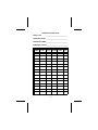
OPERATOR’S RADIO SETUP
RADIO TYPE:
______________________________
FREQUENCY BAND: ______________________________
OPERATOR’S NAME: ______________________________
EMERGENCY GROUP:_____________________________
SYSTEM
NUMBER
SYSTEM
NAME
TRK/CNV
61
GRP/CHN GRP/CHN
NUMBER
NAME
USE
SYSTEM
NUMBER
SYSTEM
NAME
TRK/CNV
62
GRP/CHN GRP/CHN
NUMBER
NAME
USE
WARRANTY
A.
B.
C.
D.
E.
Ericsson Inc. (hereinafter "Seller") warrants to the original purchaser for use (hereinafter
"Buyer") that Equipment manufactured by Seller shall be free from defects in material,
workmanship and title, and shall conform to its published specifications. With respect to any
Equipment not manufactured by Seller (except for integral parts of Seller’s Equipment to which
the warranties set forth above shall apply). Seller gives no warranty, and only the warranty, if
any, given by the manufacturer shall apply. Batteries are excluded from this warranty but are
warranted under a separate Nickel-Cadmium Battery Warranty.
Seller’s obligations set forth in Paragraph C below shall apply only to failures to meet the above
warranties (except as to title) occurring within the following periods of time from date of sale
to the Buyer and are conditioned on Buyer’s giving written notice to Seller within thirty (30)
days of such occurrence:
1. for fuses, incandescent lamps, vacuum tubes and non-rechargeable batteries, operable
on arrival only.
2. for parts and accessories (except as noted in B.1) sold by Seller’s Service Parts
Operation, ninety (90) days.
3. for all other Equipment of Seller’s manufacture, one (1) year.
If any Equipment fails to meet the foregoing warranties, Seller shall correct the failure at its
option (i) by repairing any defective or damaged part or parts thereof, or (ii) by making available
at Seller’s factory any necessary repaired or replacement parts. Any repaired or replacement
part furnished hereunder shall be warranted for the remainder of the warranty period of the
Equipment in which it is installed. Where such failure cannot be corrected by Seller’s
reasonable efforts, the parties will negotiate an equitable adjustment in price. Labor to perform
warranty service will be provided at no change only for the Equipment covered under
Paragraph B.3, and only during the first three (3) months following the date of sale to the Buyer.
Thereafter, labor will be charged at prevailing rates. To be eligible for no-charge labor, service
must be performed by an Authorized Service Center or other Servicer approved for these
purposes either at its place of business during normal business hours, for mobile or personal
equipment, or at the Buyer’s location, for fixed location equipment. Service on fixed location
equipment more than thirty (30) miles from the Service Center or other approved Servicer’s
place of business will include a charge for transportation. Equipment located off-shore is not
eligible for no-charge labor.
Seller’s obligations under Paragraph C shall not apply to any Equipment, or part thereof, which
(i) has been modified or otherwise altered other than pursuant to Seller’s written instructions
or written approval or, (ii) is normally consumed in operation or, (iii) has a normal life inherently
shorter than the warranty periods specified in Paragraph B, or (iv) is not properly stored,
installed, used, maintained or repaired, or, (v) has been subjected to any other kind of misuse
or detrimental exposure, or has been involved in an accident.
The preceding paragraphs set forth the exclusive remedies for claims (except as to title) based
upon defects in or nonconformity of the Equipment, whether the claim is in contract, warranty,
tort (including negligence), strict liability or otherwise, and however instituted. Upon the
expiration of the warranty period, all such liability shall terminate. The foregoing warranties are
exclusive and in lieu of all other warranties, whether oral, written, expressed, implied or
statutory. NO IMPLIED OR STATUTORY WARRANTIES OF MERCHANTABILITY OR FITNESS FOR PARTICULAR PURPOSE SHALL APPLY. IN NO EVENT SHALL THE SELLER
BE LIABLE FOR ANY INCIDENTAL, CONSEQUENTIAL, SPECIAL, INDIRECT OR EXEMPLARY DAMAGES.
This warranty applies only within the United States.
1-800-528-7711 (Outside USA, 804-528-7711).
ECX-362S
63
EMERGENCY NUMBERS
Police
State Police
Fire
Poison Control
Ambulance
Life Saving and
Rescue Squad
Ericsson Inc.
Private Radio Systems
Mountain View Road
Lynchburg, Virginia 24502
1-800-528-7711
(Outside USA, 804-528-7711)
Printed in U.S.A.