1
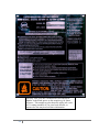
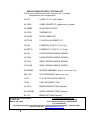
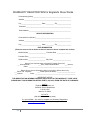
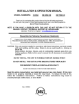
INSTALLATION AND OPERATION MANUAL
MODELS: 28-3500 , 50-SHW35 & 50-TRW35
WOOD ADD-ON FURNACE
Thank you for purchasing this product from a fine line of heating equipment.
Please read this manual before attempting to move or install your unit.
We wish you many years of safe heating pleasure with your new heating appliance.
Visit our web site at www.englanderstoves.com for helpful information, frequently asked
questions, parts & accessory orders and more.
Please Note the Following Precautionary Statements:
England’s Stove Works highly recommends the use of smoke detectors and Carbon
Monoxide detectors with any hearth product, including this unit. Follow all manufacturer’s
instructions when using smoke and Carbon Monoxide detectors.
CAUTION:
This unit must be installed in accordance with these instructions and must comply with local
building and fire codes. Failure to do so could result in a chimney or house fire.
Keep children, furniture, fixtures and all combustible materials away from any heating appliance.
Maintain a minimum clearance of 18” (18 inches) from the flue pipe to any combustibles. Refer
to information in this manual and on the unit, and to all pipe manufacturers’ instructions.
This unit is not mobile home approved.
Do not install this unit in a mobile home!
READ THESE INSTRUCTIONS CAREFULLY BEFORE INSTALLING THIS MODEL.
SAVE THESE INSTRUCTIONS FOR FUTURE REFERENCE.
INSTALLATION SHOULD BE PERFORMED BY A QUALIFIED INSTALLER.
NOTE: IF YOU HAVE A PROBLEM WITH THIS UNIT, DO NOT RETURN IT TO THE
DEALER. PLEASE CONTACT CUSTOMER SERVICE at (800) 245-6489.
FUEL: WOOD
HEATING CAPACITY: Approx. 3,000 SQ. FT (when fed into existing ductwork)
TESTED TO: UL 391, CSA-B366.1, ETLM 78.1
Rev: 2/12/2013
A letter from our Technical Support department:
Thank you for purchasing this fine product from England’s Stove Works!
England's Stove Works was started, and is still owned by, a family that
believes strongly in a "Do It Yourself" spirit – that’s one reason you found
this product at your favorite “Do It Yourself” store.
We intentionally design and build our stoves so that any homeowner can
maintain his or her unit with basic tools, and we're always more than
happy to show you how to do the job as easily and as inexpensively as
possible.
From our free, downloadable service sheets; to our Pellet Service Video; to
our new "wizard-style," click-through Troubleshooting guide on our web
site, we have always tried to help our customers stay "heat-ready,"
especially when oil and electricity prices continue to skyrocket.
Please look at our vast Help section on our web site and call our Customer
Service department at (800) 245-6489 if you need any help with your unit.
We are nearly always able to help “walk you through” any repairs,
problems or questions you may have.
PLEASE NOTE: While information obtained on our web site and through
our 800 number is always free of charge, there will be a service charge
incurred with any “on-site” repairs or maintenance that we may arrange.
Wishing you years of efficient, quality and “comfy” heating,
England’s Stove Works
Technical Support Department
www.englanderstoves.com
(800) 245-6489
IF YOU HAVE A PROBLEM WITH THIS UNIT DO NOT RETURN IT TO THE DEALER.
CONTACT CUSTOMER SERVICE at 1 (800) 245-6489.
2
SAFETY NOTICE
IF THIS UNIT IS NOT PROPERLY INSTALLED, A HOUSE FIRE MAY RESULT. FOR YOUR
SAFETY AND PROTECTION, FOLLOW ALL OF THE INSTALLATION INSTRUCTIONS.
INSTALLATION SHOULD BE PERFORMED BY A QUALIFIED INSTALLER.
CONTACT YOUR LOCAL BUILDING OR FIRE OFFICIALS FOR RESTRICTIONS AND
INSTALLATION INSPECTIONS REQUIRED IN YOUR AREA.
IMPORTANT: DO NOT OVER-FIRE. SEE “DO NOT OVER-FIRE YOUR UNIT” IN THE
“OPERATING INSTRUCTIONS” SECTION.
CAUTION – Hot Surfaces: Keep children away. Do not touch during operation.
SECTION I: FLUE SYSTEM
Note: Flue systems and flue pipe are not furnished with the unit; they must be
purchased separately. Follow all manufacturers’ instructions.
THE UNIT IS NOT TO BE CONNECTED TO A CHIMNEY FLUE SERVING ANOTHER
APPLIANCE.
This appliance requires a masonry or pre-manufactured chimney listed to
UL103HT, sized correctly.
A. Existing Flue System
The Add-On furnace is designed to connect to an existing flue system, such as
masonry or HT Pipe premanufactured flue pipe. If you have a masonry flue system,
you need to inspect the inner liner very carefully for cracks. If there is no liner in your
chimney, we recommend you install a stainless steel liner, or have one installed. If
you have an existing premanufactured flue system, it should be inspected to ensure
there are no cracks, buckling or warping. We strongly recommend that you have a
qualified chimney sweep clean and inspect your flue system.
DO NOT CONNECT THIS UNIT TO A CHIMNEY FLUE SERVING ANOTHER
APPLIANCE. Always try to position the unit as close as possible to the flue servicing
the unit. The fewer total pipes that are installed, the better the stove will draw.
B. Flue Size Required
The proper flue size is determined by the inside diameter of the flue collar on the
unit. This furnace is equipped with a 6” (6 inch) TOP EXHAUST flue collar. The
connector pipe should be six inches or larger, but never less in diameter than the
collar on the stove. The area of the chimney liner must be equal to or greater than
the area of the collar on the stove.
Example: The area of a 6” (6 inch) diameter flue collar is 28.87 square inches;
therefore, the connector pipe should be at least a 6” (6 inch) diameter pipe and the
chimney liner must be at least 28.87 square inches but no greater than 84.8 square
inches.
Connector pipe should be (at minimum) 24-gauge steel and 18” (18 inches) from a
combustible wall or ceiling. This unit is tested with single-wall pipe only.
IMPORTANT: Be sure to refer to the data label and other markings on the
appliance for additional information, including clearances to combustibles.
3
C: Installation of a New Flue System
1. Masonry Flue: If you are considering a masonry flue (see Figure 1), you should
contact your local building officials for the proper procedures required in the
construction. We recommend that you consult with and have your flue built by a
licensed, bonded contractor.
Most masonry flues are placed against the outside wall and extend up the side of
the house. A flue thimble is then inserted through the wall making the connection
with the vertical flue and the stove flue pipe. Extreme caution should be
exercised when drilling through the wall. You must maintain proper clearances
between the connecting liner and any combustible wall. We do recommend that
you have a flue clean out door at least 2’ (two feet) below the flue thimble for
easy access and cleaning. This door should be made as air tight as possible. It is
the customer’s responsibility to be sure the chimney (or flue system) is in a safe
operating condition. The manufacturer will not be held responsible for an
accident attributed to a unit connected to a faulty chimney or flue system.
2. Premanufactured Flue System: In the past few years, premanufactured flue
systems have become very popular. This type system is fairly easy to install and
when installed correctly, it is a very safe. There are many premanufactured flue
systems on the market from which to choose. In making your choice, be sure the
system has a recognized label of approval such as U.L., B.O.C.A. or I.C.B.O.
Any of these labels will ensure the flue system is constructed of the proper
materials and meets the required safety standards. Your local dealer will
normally handle an approved, high-quality flue system.
NOTE: Be sure to use “HT” Pipe.
There are two very popular methods of installing a premanufactured flue system.
The first, which is the least expensive, is up through the ceiling and out the roof
(see Figure 2). This is the most direct route and creates more draft because less
pipe is normally used. Single wall pipe (24 gauge) is used up to the ceiling, with
triple walled pipe through the attic and out the roof.
The second method of installation is to go through the wall and up the outside of
your home or structure (see Figure 2). This method is more expensive because it
requires more pipe, and once outside the home insulated or triple wall pipe is
required. Extreme care should be used in any installation, and the manufacturers’
instructions should always be followed. If you choose this type installation, a
qualified contractor or bonded chimney sweep should install this system. It is the
customers’ responsibility to be sure the flue system is in a safe operating
condition.
*IMPROPER INSTALLATION: The manufacturer will not be held responsible for damage
caused by the malfunction of a stove due to improper venting or installation. Call
800-245-6489 and/or consult a professional installer if you have any questions.
4
Installation Diagrams and Thermostat Wiring
This appliance requires a masonry or pre-manufactured chimney listed to UL103HT, sized
correctly.
18” Min.
18” Min.
18” Min.
Figure 2 – Installation into a HT Pipe Flue System.
LEFT – Through the Roof RIGHT – Through the Wall
IMPORTANT NOTE: Do NOT connect this furnace to
an external thermostat.
Figure 1 – Installation into a Masonry Flue
NOTE: 13” required from back of unit to a combustible.
16” required from sides of unit to a combustible.
See Floor and Wall Protection sections and data label
on stove for all clearances.
Recommended position
of Backflow Damper
Air Flow
Figure 3 – Hot air outlet hook-up to ductwork.
NOTE: Be sure to connect to ductwork from
furnace’s 8” hot air outlet only (see Section V).
To prevent air flow from central furnace
being directed back into the Add-on furnace:
A Backflow Damper is required in the 8” hot air
outlet pipe that connects from the Add-On
Furnace to the Central Furnace (see Figure 3).
We also recommend a 8” (eight inch), 90
degree
5 elbow (a slightly larger hole will be
required for installation) inside central furnace
plenum or ductwork.
Figure 4 – Blower thermostat wiring diagram.
SECTION II: FLOOR AND WALL PROTECTION
A. Floor Protection
There is no protection required if your floor is constructed of a
noncombustible material such as concrete. If your floor is constructed of a
combustible material such as hardwood, carpet or linoleum some type of
floor protection will be required. When selecting the required floor
protection it is important that you install a U.L. approved board. The
approved floor protection should be placed underneath the furnace, and
should be large enough to provide a minimum of 8” (8 inches) behind the
unit, 8”(8 inches) on both sides, and 16” (16 inches) at the front door(s)
location. It should also be placed underneath the chimney connector and
extend at least 2” (2 inches) on either side of the chimney connector.
B. Wall Protection
Your furnace can be placed as close as 16” (16 inches) from a
combustible wall (such as paneling, wallpaper or drywall) to the side of the
unit; from the back of the unit, 13” (13 inches) is required to a combustible.
The single-wall pipe would need to remain at least 18” (18 inches) from
combustible surfaces.
In corner installations, the unit should be placed so that the stove is at
least 12” (12 inches) from any combustibles, and the single-wall pipe
should be at least 23” (23 inches) from any combustibles in a corner
installation.
Wall protection will be required if you need to place you furnace closer
than the allowed measurements stated above, and this can be
accomplished by adding a protective board to the wall. The board can be
mounted to the wall leaving a one-inch air space between the wall and the
board. This can be done by using metal spacers, and should allow you to
place your unit so that the sides of the unit are at least 12” (12 inches)
from the protective board – be sure to check and follow the board
manufacturer’s instructions and any local codes.
SECTION III: FREESTANDING PLACEMENT AND HOOK-UP
Once you have completed your flue system and installed the floor
protection, you are now ready to place the unit. All of our stoves are well
constructed, making them very heavy. We recommend using a handcart
for moving the unit; the door and firebrick can be removed to make the
unit slightly lighter (first make a diagram of the firebrick layout for later
reference). Never attempt to handle this product alone.
After the unit is in place the flue collar, spring handles and any optional
equipment can be added.
6
Chimney Connector Pipe
This black pipe must be 6” (6 inches) in diameter and a 24-gauge or
heavier pipe. Do not use aluminum or galvanized steel, as they cannot
withstand the high temperatures of a wood fire. Do not use single wall pipe
as a chimney. You must connect your stove to a chimney comparable to
those illustrated in this manual. The chimney connector pipe lengths must
be attached to the stove, and to each other, with the crimped end toward
the stove. This will allow any creosote that might form to remain within the
pipe. As a safety precaution, all joints should be sealed with high
temperature silicone (AC-RTV3) and secured with three sheet metal
screws. For proper operation, the chimney connector should be kept as
short as possible. Horizontal lengths of chimney connector pipe should
never exceed 6’ (6 feet) and should have an upward slope of ¼” (onequarter inch) per foot.
Maintain 18” (18 inches) clearance between the wall and ceiling on any
chimney connector pipe unless wall protection is installed. If using wall
protection, the wall protection should be a U.L.-listed stove board with a 1”
(one inch) clearance (air space) between the board and the wall. This
should reduce the clearance to a combustible to 12” (12 inches).
SECTION IV: THE FUNCTION OF THE ADD-ON FURNACE
The Add-On Furnace is designed to be a supplemental hot air heating
system that will connect to your existing heating system. The furnace will
operate independently of your existing system, while using the same hot
air ducts that your present furnace uses. The furnace comes standard with
a 850 cfm (part number BM-1376) blower that pushes hot air up both
sides and across the top of the unit through an inner-duct chamber built
around the firebox. The heated air exits the unit through an eight-inch
outlet located on the top, near the front of the furnace. The eight-inch pipe
connected at this exit will route the heated air into your duct system.
A wood furnace does not recover as fast as a conventional furnace, so the
unit is equipped with a thermostat (part number AC-1339, see Figure 4) to
turn the blower on and off. This ensures that the blower will always be
moving hot air into your duct system. It is important that you maintain a
continuous fire for maximum performance.
The furnace has a “firebrick grate” system that is designed to last longer
than a standard cast iron grate system. Replacing one or two firebricks is
less expensive than a complete section of cast iron grate, and the brick
will hold more heat and make your wood last longer as it burns.
7
SECTION V: HOT AIR HOOK-UP (See Fig. 3)
NOTE: The warm air supply-duct system should be constructed of
materials with a minimum temperature rating of 250 deg. F. Also, the
plenums installed to the furnaces are to be constructed of metal.
NOTE: The hot air supply outlet of this supplementary furnace should not
be connected to the cold-air return inlet of the central furnace, since a
possibility exists that components of the central furnace could overheat in
this situation and cause the central furnace to operate other than as
intended.
Before making the hot air hook-up, you should have your unit positioned
as close to the flue connector as possible and have your flue pipe
installed. If this has not been done, please do so before continuing.
Located on the top, near the front of the unit is an eight-inch opening for
the mounting of the flue collar. When mounting this part, be absolutely
sure it is fastened securely to the opening, as this will be the hot air exit.
Thirty gauge or thicker pipe should be used from here to the hot air trunk
line of your existing hot air system. Using the least possible amount of
pipe will help the heat transfer to your duct system. Cut an eight-inch
diameter hole in the main trunk line of the furnace duct, which is usually
located on the top of the central furnace. Place the 8” (8 inch) pipe from
the wood furnace into the hole (see Figure 3) and seal the connection with
duct tape. Thirty gauge or thicker black pipe should be used for the first
two feet and then thirty gauge or thicker galvanized pipe can be used to
connect to the existing furnace duct. Sheet metal screws should be used
to secure each joint of pipe, and an aluminum heat resistant tape can be
wrapped around each joint to give an airtight seal. See Figure 3 for more
information, including the use of a Backflow Damper. Follow the
manufacturer’s instructions when installing a Backflow Damper.
SECTION VI: BLOWER AND THERMOSTAT INSTALLATION
A. Blower Installation
The BM-1376 blower will be mounted to the opening that is located at the
bottom on the rear of the stove. The blower will simply mount to the
opening with the five screws that are installed on the unit.
The heat circulation blower on this furnace requires periodic lubrication; this lubrication should
be performed no less than every three months of normal operation. To properly lubricate the
blower, use an eye dropper or similar dispensing device to drip 5-7 droplets of SAE 20 oil into
the oil port on the side of the blower motor.
8
B. Thermostat Installation
The thermostat, blower and power cord are all prewired (see Figure 4 for
thermostat instructions); however, the thermostat must be connected to
the furnace after installation of the blower. Do this by inserting the probe
portion into the stove (remove the cover first, to reveal the mounting plate)
and fastening the thermostat to the unit with the four screws that are
mounted on the furnace. Refer to the following illustraton:
Probe thermostat mounts in top rear
(4 screws)
Blower mounts on bottom rear
(5 screws)
SECTION VII: OPERATING INSTRUCTIONS
A. Building a Fire
NOTICE:
Do not operate unit with bottom (ash) door open.
Operating unit with ash door open can cause over-firing and damage
the unit, and will void any warranty.
Except as specified in “Operating Instructions,” do not operate unit
with fuel (main) door open.
BURN WOOD ONLY
CAUTION: Do not elevate the fire. Build fire directly on the floor of the unit.
9
Notice: The surface of your new furnace and the connector pipe may
smoke for a short time, and this is no cause for alarm. This is called
“cooking out,” and it is advisable to open doors and windows in your
dwelling during the first two hours (approximately) of operation.
1. Place several pieces of crushed paper evenly over the entire bottom of
the firebox and lay small dry sticks of kindling on top of the paper.
2. Open the draft on the bottom door by unscrewing it (counterclockwise);
move the top draft all the way to the left.
3. Check to be sure there are no combustible materials in the immediate
area of the stove. Be sure the room is adequately ventilated and the
flue is unobstructed.
4. Ignite the paper and close the door until there is a ½” (one-half inch)
opening. Leave the ash door at the bottom of the stove completely
closed. Allow the paper and kindling to burn freely for 10 to 15
minutes.
5. Once the kindling is burning freely, slowly open the door and add
several pieces of dry split wood to the fire. Continue to leave the ½”
(one-half inch) crack in the door and allow the stove to burn another 15
to 20 minutes.
6. Once the split wood has burned to a charcoal base, then you can fill
the firebox with seasoned wood. Allow the unit to burn for another 15
to 20 minutes with the ½” (one-half inch) crack in the door.
7. Close the door completely and tighten the bottom draft to the closed
position (clockwise). Move the top slide draft damper all the way to the
right (closed), then select your heat level by moving it back to the left.
Note: The proper setting will be determined by the draw of your
individual flue system.
DANGER- RISK OF FIRE OR EXPLOSION
DO NOT BURN GARBAGE, GASOLINE, DRAIN OIL OR OTHER FLAMMABLE
LIQUIDS
NEVER USE GASOLINE, GASOLINE-TYPE LANTERN FUEL, KEROSENE,
CHARCOAL LIGHTER FLUID, OR SIMILAR LIQUIDS TO START OR
‘FRESHEN UP’ A FIRE IN THIS HEATER. KEEP ALL SUCH LIQUIDS WELL
AWAY FROM THE HEATER WHILE IN USE.
WARNING – RISK OF FIRE
Do not operate with flue draft exceeding .05 in. water column.
Do not operate with fuel loading or ash removal doors open.
Do not store fuel or other combustible material within marked installation
clearances, or anywhere near unit.
Inspect and clean flues and chimney regularly.
In the event of a POWER FAILURE, close the bottom “spin” draft completely.
10
B. Draft Controls
This unit has a draft control system that is used to determine the
amount of combustion air that enters the stove. The more the controls
are opened, the more air will enter the firebox and thereby increase the
heat output of the unit. This will, by creating a hotter fire, make your
fuel burn faster. Pushing the slide draft located above the door to the
left opens the damper, and unscrewing the bottom screw damper
(counterclockwise) located on the bottom ash door opens that control.
No two flue systems are identical; you will have to experiment with
your furnace draft settings to achieve the maximum burn time and heat
output. If you have any problem regulating the furnace, consult your
local dealer or our Customer Service department at (800) 245-6489.
C. Do Not Over-Fire Your Unit
IMPORTANT: Using flammable liquids, too much wood, or burning
trash in this unit may result in over-firing. If the chimney connector
pipe glows red or — even worse — white, the stove is over-fired. This
condition could ignite creosote in the chimney, which in turn could
cause a house fire.
CAUTION: If you do over-fire the unit, immediately close the draft
controls and the door if it is open. You should get out of the house and
call the fire department. Do not use the stove again until the chimney
and connector pipe have been inspected and any damaged parts
replaced. A chimney sweep can perform the inspection and make any
necessary repairs.
D. Everyday Fueling
This furnace is designed to burn six to eight hours on one filling of
good seasoned wood. To refuel the unit, proceed as follows:
1. Open both draft controls as described previously. Crack the door
approximately 1” (one inch) and leave it in this manner for two to five
minutes. This will allow the excess smoke to go up the chimney system
by increasing the draft.
2. Now you can slowly open the door; you should see a hot bed of coals
in the firebox. If the fire has burned out, stop here and refer to the
procedure for “Building a Fire.”
11
3. Use a poker to rake the dead ashes through the grates into the ash
pan. Be sure to leave some “live” ashes in the firebox.
4. Fill the firebox with dry seasoned wood and leave the door cracked
approximately 1/2” (one-half inch). Allow the fire to burn in this manner
for 15 to 20 minutes.
5. Close the door completely, leaving both draft controls in the open
position, and allow the furnace to burn in this manner for another 5 to
10 minutes.
6. Close both draft controls, then open both controls to your desired
setting as described previously in “Building a Fire.”
E. Ash Removal and Disposal
The small door below the firebox contains an ash pan, and how often it is
dumped will be determined by the manner in which the stove is used. Be
sure the ashes in the pan are cooled down before removing the pan.
Using heavy gloves to protect your hands, open the small door and slide
out the ash pan.
Disposal of Ashes – Ashes should be placed in a metal container with a
tight fitting lid. The closed container of ashes should be placed on a
noncombustible floor or on the ground, well away from all combustible
materials, pending final disposal. If the ashes are disposed of by burial in
soil or otherwise locally dispersed, they should be retained in the closed
container until all cinders have thoroughly cooled.
After emptying the ashes, the ash pan can be placed back into the unit
and the small door closed.
Never leave the ash door open or the unit unattended.
F. Creosote
Creosote – Formation and Need for Removal
When wood is burned slowly, it produces tar and other organic vapors,
which combine with expelled moisture to form creosote. The creosote
vapors condense in the relatively cool chimney flue of a slow-burning fire.
As a result, creosote residue accumulates on the flue lining. When
ignited, this creosote makes an extremely hot fire. The chimney connector
and chimney should be inspected at least twice monthly during the heating
season to determine if a creosote buildup has occurred. If creosote has
accumulated it should be removed to reduce the risk of a chimney fire.
12
SECTION VIII: CARE AND MAINTENANCE
(Unit must be cool and power unplugged
before performing any maintenance)
A. Gaskets
Refer to the list at the rear of this
manual for part numbers.
You may order parts by calling
(800) 516-3636 or logging on to
www.englanderstoves.com .
Each unit comes with a rope gasket around the door, which should be
replaced at least every two years. To replace the gasket, the old gasket
material should be removed and the door channel scraped free of any
adhesive. You can then add the new adhesive and the gasket
(Part AC-DGKC) and close the door. The door should be closed for at
least twenty-four hours to allow the adhesive to harden.
B. Firebrick
This furnace is equipped with high density, high temperature firebrick. Any
brick that become chipped or cracked, especially on the sides of the
firebox, need to be replaced.
C. Finish
This unit is coated with high-temperature paint that will retain its original
look for several years. If the unit should get wet, rust spots may appear;
these can easily be covered with this high-temperature spray paint (plain
steel wool can be used to remove the rust spots before repainting). Please
contact your dealer or the factory for this paint, as other brands may not
adhere to the surface of this furnace.
D. Blower and Thermostat
This furnace comes with a 850 CFM blower (Part BM-1376). Over a
period of time the intake of the blower can become clogged with lint or
dust, and it will require some cleaning. To do this, unplug the blower from
the power source and remove the screws that hold the blower to the stove
(be sure the stove is cool before doing so). Then unscrew the motor from
the blower and remove it, along with the impeller. A vacuum cleaner can
be used to remove the foreign material from the intake. Reverse this
procedure to re-mount the blower to the furnace.
The AC-1339 thermostat requires no maintenance. It activates the blower
when the firebox temperature rises to 125 degrees Fahrenheit; it also
deactivates the blower when the temperature drops to 95 degrees
Fahrenheit. By shutting off at 95 degrees, it allows the furnace to recover
as the heat is extracted from the unit and forced through the duct system.
We recommend that you leave the thermostat at the factory settings
until the unit has been burned for at least 30 days.
13
E. Baffle Plate
This furnace has a large baffle plate (Part IP-2835) that is located in the
top of the firebox. This baffle plate lays on an angle iron track and can be
removed by sliding it out of the unit. If the baffle becomes warped, it can
be replaced by calling (800) 516-3636 or logging on to:
www.englanderstoves.com .
Caution: Allow the furnace to cool down before removing the baffle
plate or performing any maintenance.
SECTION IX: CHIMNEY AND FLUE PIPE MAINTENANCE
A: Chimney Maintenance
Cleaning your chimney is not a difficult task; however, we recommend a
professional do this job. A professional chimney sweep can detect
problems in your system that you might not recognize.
B. Flue Pipe Maintenance
If you are connecting your unit to a masonry or premanufactured chimney
you should use 24-gauge or thicker pipe (the thicker the pipe that is used,
the longer it will last). This pipe will require some maintenance, and it
should be cleaned as needed. A chimney sweep can do this job and also
evaluate when the pipe needs replacing.
Note: It is a good practice to clean your flue system in the spring to
eliminate any lingering odor through the summer months.
SECTION X: THINGS THAT COULD CAUSE THE UNIT TO SMOKE
It is very important that all pipe connections be made airtight. This can be
done with stove cement (or high-temperature silicon) and sheet metal
screws at each pipe joint. If the joints are not airtight, air can be drawn
through these areas, affecting the efficiency and/or safety of the unit.
Ideally, all combustion air will be drawn through the draft controls on the
furnace. If there is a clean-out door on your chimney, this should also be
sealed in some manner to make it airtight.
Downdrafts: One cause for chimney downdrafts is air being deflected
down the chimney by nearby objects such as the roof, trees or a nearby
hill. Another cause is flue gas being chilled as it passes through the flue
system. A typical example of this would be the flue system cooling down
and the smoke not being able to exit the system, thereby building up in the
chimney. The chimney will then “back puff” if there is wind blowing across
the top of the flue system. This situation can normally be avoided if the
furnace runs at a sustained temperature, thus not allowing the system to
cool down.
14
You may write your unit’s Manufacture Date and Serial
Number in the blank spaces on this sample tag, for future
reference. This sample tag also shows the safety info. such
as UL testing standard, etc. for your local officials, or
anyone else who may need reference information.
15
LIMITED 5 YEAR WARRANTY
FROM THE DATE OF PURCHASE TO THE ORIGINAL OWNER
The manufacturer extends the following warranties:
Five Year Period:
1. Carbon steel and welded seams in the firebox are covered for 5 years against
splitting.
2. The cast iron door, hasp and hinges are covered for 5 years against cracking.
One Year Period:
3. Component parts such as combustor housing, flue collar, flame impingement
plate, baffle plate, brick retainers, combustor plate and fasteners are covered
for 1 year against cracking, breakage and welded seams from separating.
4. Electrical components, accessory items, firebrick, glass and the painted
surface are covered for 1 year from the date of purchase.
Conditions and Exclusions:
Damage from over-firing will void your warranty.
This warranty does not apply if damage occurs because of an accident, improper
handling, improper operation, improper installation, abuse, or unauthorized repair
made or attempted to be made.
The manufacturer is not liable for indirect, incidental, or consequential damages
in connection with the product including any cost or expense providing substitute
equipment or service during periods of malfunction or nonuse.
All liability for any consequential damage for breach of any written or implied
warranty is disclaimed and excluded. Some states do not allow the exclusion or
limitations of incidental or consequential damages, so the above may not apply to
you.
Procedure:
Purchaser must give notice of claim of defect within the warranty period and pay
transportation to and from a service center designated by the factory. The dealer
from which the unit was purchased or the factory, at our option, will perform the
warranty service.
Other Rights:
This warranty gives you specific legal rights, and you may also have other rights,
which may vary from state to state.
NOTE: THIS WARRANTY IS NULL AND VOID IF YOU DO NOT REGISTER
WITHIN 30 DAYS FROM THE DATE OF PURCHASE.
WARRANTY IS NOT TRANSFERABLE.
16
ADD-ON FURNACE PARTS / OPTIONS LIST
(Check your model for paint color, trim color, etc. if ordering
a replacement for an original part).
AC-G9
GLASS (9” X 9”), with Gasket
AC-GGK
GLASS GASKET KIT (gasket only, no glass)
AC-MBSP
BLACK SPRAY PAINT
AC-1339
THERMOSTAT
AC-DGKC
DOOR GASKET KIT
AC-FCGK
FLUE COLLAR GASKET KIT
AC-SB
FIREBRICK (9”X4”X1 ¼”) (21 qty.)
AC-SB7.75
FIREBRICK (7.75”X4”X1 ¼”) (5 qty.)
AC-SH
LARGE SPRING HANDLE (BRASS)
AC-SHN
LARGE SPRING HANDLE (NICKEL)
AC-SH4
SMALL SPRING HANDLE (BRASS)
AC-SH4N
SMALL SPRING HANDLE (NICKEL)
AC-2835BA
BLOWER ASSEMBLY (Blower, Thermostat & Cord)
BM-1376
850 CFM BLOWER (Blower motor only)
CA-21
8” FLUE COLLAR WITH BOLTS
CA-24
CAST IRON DRAFT CAP
AC-106-P
BRASS WINDOW TRIM (Optional)
AC-106-PBN
NICKEL WINDOW TRIM (Optional)
AC-119
BRASS LIP TRIM (Optional)
Customer Service Department
P.O. Box 206
Monroe, VA 24574
[email protected]
Parts Orders ONLY: (800-516-3636)
Tech. Questions/Problems: (800-245-6489)
(Fax: 434-929-4810)
All replacement parts can be ordered from our factory at (Parts Orders ONLY): 1-800-516-3636,
or from our web site: www.englanderstoves.com .
17
18
WARRANTY REGISTRATION for England’s Stove Works
Purchased by (Name) ______________________________________________
Address _________________________________________________________
City ________________________ State __________ Zip _________________
Telephone _______________________________________________________
Email Address ___________________________________________________
DEALER INFORMATION
Purchased From (Dealer) ___________________________________________
Address _________________________________________________________
City ________________________ State __________ Zip _________________
UNIT INFORMATION
(Please be sure to refer to sticker on back of manual or box to complete this section)
Model Number _____________________ Purchase Date _________________
Purchase Price ____________________
Serial Number _____________________ Mfg. Date ______________________
How did you first hear about our product? (please check one)
___ Word of Mouth
___ Burn Trailer Demonstration
___ Internet
Other: ____________________________________________________
Where did you receive information about our product? (please check one)
___ Rec’d. info. via phone
___ Dealer (Name of dealer): ______________________
___ Internet
Other: _________________________________________________
IMPORTANT NOTICE
THIS REGISTRATION INFORMATION MUST BE ON FILE FOR THIS WARRANTY TO BE VALID.
PLEASE MAIL THIS INFORMATION WITHIN THIRTY (30) DAYS FROM THE DATE OF PURCHASE.
Mail To:
England’s Stove Works, Inc.
Customer Service Department
P.O. Box 206
Monroe, VA 24574
Or, Fax To:
(434) 929-4810 – 24 hours a day
Or, now available – Go online to complete your Warranty Registration!
Visit www.englanderstoves.com if you prefer to register online.
19