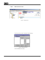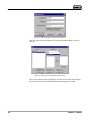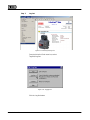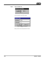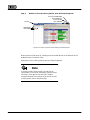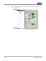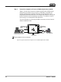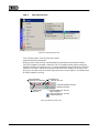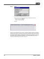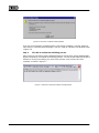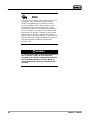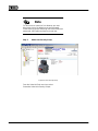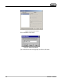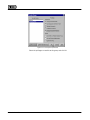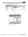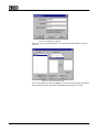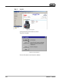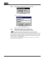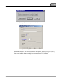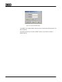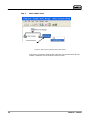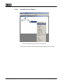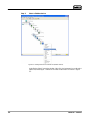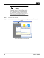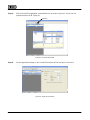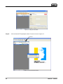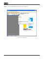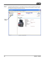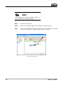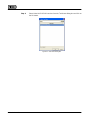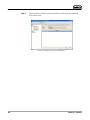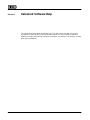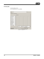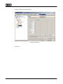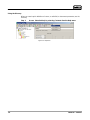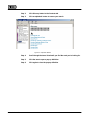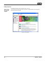
1
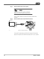
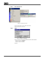
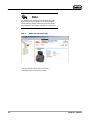
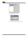
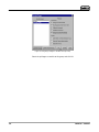
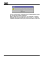
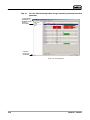
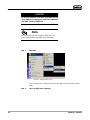
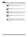
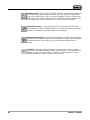
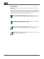
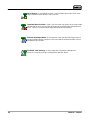
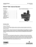
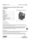
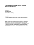
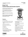
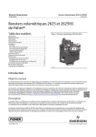
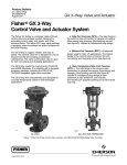
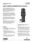
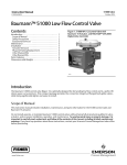
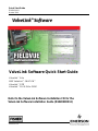
Quick Start Guide
D102813X012
October 2010
ValveLink Software Quick Start Guide
ValveLinkt Solo
AMS ValveLinkt SNAP-ONt
ValveLinkt DTM
ValveLinkt PLUG-IN for PRMr
Refer to the ValveLink Software Installation CD for the
ValveLink Software Installation Guide (D102800X012)
www.Fisher.com
FIELDVUE, PlantWeb, ValveLink, and Fisher are marks owned by Fisher Controls International
LLC, a member of the Emerson Process Management business division of Emerson Electric Co.
AMS Suite, DeltaV and SNAP-ON are marks of one of the Emerson Process Management group
of companies. The Emerson logo is a trademark and service mark of Emerson Electric Co. HART
is a mark owned by the HART Communications Foundation. FOUNDATION fieldbus is a mark
owned by the Fieldbus Foundation. All other marks are the property of their respective owners.
© Fisher Controls International, LLC. 2002-2004; All rights reserved.
While this information is presented in good faith and believed to be accurate, Fisher does not
guarantee satisfactory results from reliance upon such information. Nothing contained herein is to be
construed as a warranty or guarantee, expressed or implied, regarding the performance,
merchantability, fitness or any other matter with respect to the products, nor as a recommendation to
use any product or process in conflict with any patent. Fisher reserves the right, without notice, to
alter or improve the designs or specifications of the products described herein. Fisher does not
assume responsibility for the selection, use, or maintenance of any product. Responsibility for proper
selection, use and maintenance of any Fisher product remains solely with the purchaser and
end-user.
Table of Contents
Quick Start for ValveLink Solo for HARTr
Instruments . . . . . . . . . . . . . . . . . . . . . . . . . . . . . . . . . . . . . 1-1
Quick Start for ValveLink Solo for
FOUNDATIONt fieldbus Instruments . . . . . . . . . . . . . 2-1
Quick-Start for AMS ValveLink SNAP-ON . . . . . . . 3-1
Quick-Start for ValveLink DTM . . . . . . . . . . . . . . . . . . 4-1
Quick-Start for ValveLink PLUG-IN for PRM . . . . . 5-1
ValveLink Software Toolbar Buttons
and Icons . . . . . . . . . . . . . . . . . . . . . . . . . . . . . . . . . . . . . . . . 6-1
ValveLink Software Help . . . . . . . . . . . . . . . . . . . . . . . . . 7-1
ValveLinkt Software
Note
Neither Emerson, Emerson Process Management,
nor any of their affiliated entities assumes
responsibility for the selection, use, or
maintenance of any product. Responsibility for the
selection, use, and maintenance of any product
remains with the purchaser and end user.
ValveLinkt Software
Section 1
Quick Start for ValveLink Solo for HART
Instruments
11
This section contains quick-start information for ValveLink Solo connected to HART
communicating instruments through a HART modem. Information about connecting HART
multiplexers is available in the ValveLink Software Installation Guide. For more information on
using ValveLink Solo, see ValveLink help. For information on using ValveLink software toolbar
buttons, see section 6 of this document. Section 7 provides information on ValveLink help.
Note
This section assumes ValveLink Solo is installed. The
ValveLink Software Installation Guide, found on the
ValveLink Software installation CD, provides detailed
installation information.
ValveLinkt Software
1-1
Step 1:
Attach the HART modem to the computer
Note
If you do not have a HART modem or FIELDVUE
digital valve controller available, proceed to Step 3.
Attach the HART modem to the serial port (COM port) selected during
installation.
Step 2:
Attach the HART modem to the FIELDVUE instrument
Connect to PC
Serial Port
Modem
E0350 / IL
Figure 1-1. Instrument Connections
Clip the HART modem leads to the FIELDVUE instrument TALK terminals.
Apply 4-20 mA power to the FIELDVUE Instrument LOOP + and − terminals.
1-2
ValveLinkt Software
Step 3:
Start ValveLink Solo
Figure 1-2. Starting ValveLink Solo
Click the Start button. From the Start menu select
Programs>ValveLink>ValveLink.
Step 4:
Log in
Figure 1-3. Logging in as MANAGER.
Log in to ValveLink Solo with the Default User Name and Password
Default User Name: MANAGER
Default Password: FALCON
Click OK.
ValveLinkt Software
1-3
Note
For full access to ValveLink Solo features you must
discontinue use of the default name and password.
Create security groups and assign new user names
and passwords, then logout and login as a new user.
Step 5:
Add a New Security Group
From the ValveLink Solo menu bar, select:
Customize ValveLink>Security Groups.
1-4
ValveLinkt Software
Figure 1-4. Adding a New Security Group
Click the Add New Group button.
Figure 1-5. Naming the New Security Group
Type a name for the new security group, then click the OK button.
ValveLinkt Software
1-5
Figure 1-6. Assigning Privileges to the New Security Group
Select the privileges accessible to this group and click OK.
1-6
ValveLinkt Software
Step 6:
Add a New User Account
Figure 1-7. Selecting Users
From the menu bar, select: Customize ValveLink>Users.
Figure 1-8. Adding a New User
Click the Add New User button.
ValveLinkt Software
1-7
Figure 1-9. Entering the New User Name and Password
Type in a user name and password. Then type the password again to verify it.
Click OK.
Figure 1-10. Assigning a Security Group to the New User
Click on the new user name to highlight it. Click the list box arrow to the right of
the Security Group box and select the desired security group. Click OK.
1-8
ValveLinkt Software
Step 7:
Log Out
Figure 1-11. Selecting Exit/Log Out
From the ValveLink Solo menu bar, select:
Tag>Exit/Log Out.
Figure 1-12. Logging Out
Click the Log Out button.
ValveLinkt Software
1-9
Step 8:
Log In as a New User
Figure 1-13. Logging In
Click the ValveLink Solo Log In button.
Figure 1-14. Logging in as New User
Enter your user name and password. Click OK.
1-10
ValveLinkt Software
Step 9:
Double click on the valve symbol to open the Status diagnostic
CLICK TO CLOSE WINDOW AND
EXIT VALVELINK SOLO
CLICK TO RESTORE
TITLE BAR
CLICK TO MINIMIZE
MODEM SYMBOL
VALVE SYMBOL
Figure 1-15. Device Connection View Showing Connected Devices
When ValveLink Solo starts up, it displays the connected devices in the left pane of the
window (Device Connection View).
Double click on the valve symbol to open the Status Diagnostic.
Note
If you do not see a valve symbol, you may not be
connected to a FIELDVUE instrument. Recheck Step 1
and Step 2, then right click on the HART modem
symbol and select Scan for New. If you still do not see
a valve symbol, refer to ValveLink Help.
ValveLinkt Software
1-11
Step 10:
Click the Start Monitoring button to begin monitoring instrument and valve
parameters
TITLE BAR DISPLAYS
INSTRUMENT TAG
STATUS BAR DISPLAYS
TAG INFORMATION
Figure 1-16. Start Monitoring
1-12
ValveLinkt Software
Section 2
Quick Start for ValveLink Solo for FOUNDATION
fieldbus Instruments2
This section contains quick start information for ValveLink Solo connected to a single FOUNDATION
fieldbus instrument. For more information about connecting to a single instrument, or for
information about connecting to an H1 segment, see the ValveLink software Installation Guide.
For more information on using ValveLink Solo see ValveLink software help. For information on
using ValveLink software toolbar buttons, see section 6 of this document. Section 7 provides
information on ValveLink software help.
Communicating with FOUNDATION fieldbus instruments requires National Instruments NI-FBUS
hardware and software be installed on the computer running ValveLink Solo.
Note
This section assumes ValveLink Solo and the
associated National Instruments hardware and software
are installed. The ValveLink Software Installation
Guide, found on the ValveLink software installation CD,
provides information for installing these components.
ValveLinkt Software
2-1
Step 1:
Connect the computer to a FOUNDATION fieldbus digital valve controller
Figure 2-1 shows how to connect to a single instrument with a fieldbus power
hub (Relcom part number FCS-PH-110-PL, or equivalent). The power hub
provides a power supply and double terminator. Up to four devices can be
connected to the Relcom power hub. The computer with ValveLink Solo and the
NI-FBUS interface card is considered as one device. This product is used for
bench testing. It is not designed for field applications.
For more information on connecting to fieldbus instruments, see the ValveLink
software Installation Guide.
FOUNDATION FIELDBUS
POWER HUB 1
CONNECTION FOR
ANOTHER FIELDBUS
DEVICE
+
+
S
S
−
−
+
+
S
S
−
−
COMPUTER WITH VALVELINK SOLO
AND NI-FBUS INTERFACE CARD
CONNECTION FOR
ANOTHER FIELDBUS
DEVICE
POWER INDICATOR
DVC6000f DIGITAL
VALVE CONTROLLER
9 TO 32 VDC
POWER SUPPLY
NOTE
1 RELCOM PART NUMBER FCS-PH-110-PL OR EQUIVALENT
Figure 2-1. Typical Connection to a Single FOUNDATION fieldbus Digital Valve Controller
2-2
ValveLinkt Software
Step 2:
Start ValveLink Solo
Figure 2-2. Starting ValveLink Solo
Click the Start button. From the Start menu select:
Programs>ValveLink>ValveLink.
When you start ValveLink Solo it will automatically start National Instruments Fieldbus
(NI-FBUS) software if installed. If ValveLink Solo is shutdown without properly exiting the
software, NI-FBUS will continue to run. So, before starting ValveLink Solo be sure NI-FBUS
software is shut down. ValveLink Solo will not start if NI-FBUS software is running. A blue
box icon in the system tray in the lower right corner of the screen (figure 2-3) indicates when
NI-FBUS software is running.
INDICATES NETWORK
CONNECTION (TAG CONNECTED)
INSTRUMENT LEVEL
INDICATES VALVE TYPE
VALVELINK SOFTWARE STATUS BAR
WINDOWS SYSTEM TRAY
INDICATES IN/OUT
OF SERVICE
NI-FBUS SOFTWARE ICON − “BLUE BOX”
PRIOR TO VERSION 3.0
NI-FBUS SOFTWARE ICON − “BLUE BOX”
VERSION 3.0 AND LATER
Figure 2-3. Windows System Tray
ValveLinkt Software
2-3
Step 3:
Log in
Figure 2-4. Logging in as MANAGER
Login to ValveLink Solo with the Default User Name and Password:
Default User Name: MANAGER
Default Password: FALCON
Click OK.
Figure 2-5. ValveLink Solo NI-FBUS Startup Window
ValveLink Solo starts the NI-FBUS software. As NI-FBUS software initializes, the startup
window, shown in figure 2-5, appears. Do not stop the initializing process so that ValveLink
Solo may start up successfully. During this time, ValveLink Solo is “listening” to see if it is
connected to a fieldbus segment controlled by a Link Active Scheduler (LAS). If it is, then it
starts the NI-FBUS Communications Manager in the non-LAS mode and the process
continues, as indicated by the box shown in figure 2-7.
2-4
ValveLinkt Software
Figure 2-6. ValveLink Link Master Starting Window
If you are not connected to a segment where a Link Active Scheduler is running, ValveLink
Solo starts the Communications Manager in the LAS mode as indicated in the window shown
in figure 2-6.
Step 4:
Click OK to continue the initializing process.
After ValveLink Link Master Starting window disappears, the NI-FBUS startup window again
appears temporarily to complete the initializing process. The last window states that NI-FBUS
software is running and cautions you not to kill the process or the process will not be
complete, as shown in figure 2-7.
Figure 2-7. ValveLink Link Master NI-FBUS Running Window
ValveLinkt Software
2-5
Note
The Link Active Scheduler (LAS) controls traffic on the
H1 segment. For an active H1 segment, the LAS
function is provided by the host system or another
FOUNDATION fieldbus device. When ValveLink Solo is
connected (to either an active segment or a single
instrument), the NI-FBUS interface card waits to see if
the LAS is present. If not, the NI-FBUS interface card
provides the LAS function. Therefore, to avoid conflict
between the LAS function in the NI-FBUS interface
card and LAS on the active segment, do not disconnect
ValveLink Solo from a single instrument and connect it
to an active segment without first shutting down
ValveLink Solo.
WARNING
To avoid personal injury or property damage due to
loss of process control, do not connect the
computer to an active H1 segment while ValveLink
Solo or NI-FBUS software is running. Doing so
could interfere with Link Active Scheduler (LAS)
operation.
2-6
ValveLinkt Software
Note
For full access to ValveLink Solo features you must
discontinue use of the default name and password.
Create security groups and assign new user names and
passwords, then logout and login as a new user.
Step 5:
Add a New Security Group
Figure 2-8. New Security Group
From the ValveLink Solo menu bar, select:
Customize ValveLink>Security Groups.
ValveLinkt Software
2-7
Figure 2-9. Security Groups Window
Click the Add New Group button.
Figure 2-10. Add New Group Window
Type a name for the new security group, then click the OK button.
2-8
ValveLinkt Software
Figure 2-11. Security Groups Window
Select the privileges accessible to this group and click OK.
ValveLinkt Software
2-9
Step 6:
Add a New User Account
Figure 2-12. Add New User
From the menu bar, select Customize ValveLink>Users.
Figure 2-13. Users Window
Click the Add New User button.
2-10
ValveLinkt Software
Figure 2-14. Add New User Window
Type in a user name and password. Then type the password again to verify it.
Click OK.
Figure 2-15. Selecting Security Group
Click on the New User name to highlight it. Click the list box arrow to the right of
the Security Group box and select the desired security group. Click OK.
ValveLinkt Software
2-11
Step 7:
Log Out
Figure 2-16. Log Out
From the ValveLink Solo menu bar, select:
Tag > Exit / Log Out.
Figure 2-17. Exit ValveLink
Click the Exit button to exit ValveLink software.
2-12
ValveLinkt Software
Step 8:
Restart ValveLink Software and Log In as a New User
Figure 2-18. Logging In
Click the Log In button.
Figure 2-19. OK for Login Button
Enter your user name and password. Click OK.
Step 9:
After NI-FBUS completes start up, double click the
instrument icon to open its tag for the status monitor.
If a
appears over the instrument symbol ValveLink Solo is not connected to the
instrument. A possible reason for not connecting may be that the instrument is at a
temporary address. ValveLink Solo will not connect to an instrument at a temporary address.
If the instrument is at a temporary address, the Temporary Address window shown in figure
2-20 appears when you attempt to open the instrument tag. To change the device tag and
address, click the Change Address button.
On the Change Device Tag and Address window, shown in figure 2-21, enter a working
address for the device. Address 35 is
ValveLinkt Software
2-13
Figure 2-20. Digital Valve Controller at a Temporary Address.
Click Change Address to change the Device Tag and Address
Figure 2-21. Changing the Device Address
preferred. However, if you are connected to an H1 segment, address 35 may be in use by
another device. Select an unused address between 21 and 35. Click Set Address then click
the Change Address button to assign the new address. When the address
2-14
ValveLinkt Software
Figure 2-22. Reminder of Instrument Address Change
changes, click the Done button. The instrument should be connected and you may proceed
with instrument startup, calibration, and diagnostics.
When you attempt to log out or exit ValveLink Solo, if the instrument was at a temporary
address when you started, the message shown in figure 2-22 appears. You may leave the
instrument at the set address or allow it to return to the temporary address. Click No to keep
the set address or Yes to return to a temporary address.
ValveLinkt Software
2-15
Step 10:
Click the Start Monitoring button to begin monitoring instrument and valve
parameters
TITLE BAR DISPLAYS
INSTRUMENT TAG
INSTRUMENT SYMBOL
CHANGES TO
VALVE SYMBOL
STATUS BAR
DISPLAYS TAG
INFORMATION
Figure 2-23. Start Monitoring
2-16
ValveLinkt Software
Section 3
Quick Start for AMS ValveLink SNAP-ON3
This section contains quick start information for AMS ValveLink SNAP-ON. For more information
on using AMS ValveLink SNAP-ON see ValveLink software help. Section 7 of this document
provides information on ValveLink software help. For more information on using AMS Suite:
Intelligent Device Manager, see the associated help.
Note
This section assumes AMS Device Manager and AMS
ValveLink SNAP-ON are installed. See AMS Device
Manager documentation for installation information. The
ValveLink Software Installation Guide, found on the
ValveLink software installation CD, gives detailed
installation information for installing the AMS ValveLink
SNAP-ON.
ValveLinkt Software
3-1
CAUTION
Do not run ValveLink Solo at the same time you are
using AMS Device Manager or AMS Device Manager
with AMS ValveLink SNAP-ON.
Note
To successfully use AMS ValveLink SNAP-ON, you
must be familiar with using AMS Device Manager.
Step 1:
Start AMS
Figure 3-1. Enter the AMS System
Click a desktop icon or select AMS Device Manager from the Programs>AMS
menu.
Step 2:
3-2
Log in to AMS Device Manager
ValveLinkt Software
Figure 3-2. Login to the AMS System
In the AMS User Login window, enter the correct Username and Password. Click
OK to continue.
Continue on with Step 3 to select a HART device. Go to Step 5 to select a
fieldbus device.
ValveLinkt Software
3-3
Step 3:
Select a HART device
Communication Devices
Figure 3-3. AMS Device Connection View (HART Device)
In the Device Connection View window, right click the communication devices
(modem, multiplexer) icon and select Scan All Devices.
3-4
ValveLinkt Software
Step 4:
Start AMS ValveLink SNAP-ON
Figure 3-4. Starting AMS ValveLink SNAP-ON (HART Device)
Right click the instrument icon and select ValveLink from the context menu.
ValveLinkt Software
3-5
Step 5:
Select a fieldbus device
Figure 3-5. Starting AMS ValveLink SNAP-ON (fieldbus Device)
In the Device View Connection window, right click the instrument icon and select
SNAP-ON/Linked Apps > ValveLink from the context menu as shown in figure
3-5.
3-6
ValveLinkt Software
Section 4
Quick Start for ValveLink DTM
42
This section contains quick start information for ValveLink DTM. For more information on using
ValveLink DTM see ValveLink software help. Section 7 of this document provides information on
ValveLink software help.
Note
This section assumes ValveLink DTM is installed. The
ValveLink Software Installation Guide, found on the
ValveLink software installation CD, provides detailed
installation information.
ValveLinkt Software
4-1
Note
To successfully use the ValveLink DTM, you must be
familiar with using the FDT frame application used to
launch the ValveLink DTM. The information found in
this section covers one example. Refer to the users
guide for the FDT frame application that the ValveLink
DTM is installed with for additional information.
Step 1:
Start the FDT frame application.
Step 2:
Select Add Device, as shown in figure 4-1, and click on the appropriate CommDTM. Select OK.
Add Device
Figure 4-1. Select Add Device to Add the CommDTM
4-2
ValveLinkt Software
Step 3:
With the CommDTM highlighted, select Add Device, as shown in figure 4-2, and click on the
appropriate Device DTM. Select OK.
Add Device
Figure 4-2. Select the DeviceDTM
Step 4:
Set the appropriate settings for the CommDTM and DeviceDTM (see figure 4-3 and 4-4).
Figure 4-3. Setting the CommDTM
ValveLinkt Software
4-3
Figure 4-4. Setting the DeviceDTM
Step 5:
With the DeviceDTM highlighted, select Connect as shown in figure 4-5.
Connect
Figure 4-5. Connect the DeviceDTM
4-4
ValveLinkt Software
Step 6:
Once connected, select ValveLink DTM as shown in figure 4-6.
Right Click on the Device Type and
Select Additional functions to Access
ValveLink DTM
Figure 4-6. Select ValveLink DTM
ValveLinkt Software
4-5
Step 7:
The ValveLink DTM will launch in a new window. All devices currently connected in the FDT frame
application will show in the tree menu to the left of the ValveLink DTM window, as shown in figure
4-7. Double-click the device to open the device tag.
Double-Click
to open the
device tag
Figure 4-7. ValveLink DTM
4-6
ValveLinkt Software
Section 5
Quick Start for ValveLink PLUG-IN
for PRM
53
This section contains quick start information for ValveLink PLUG-IN for PRM. For more
information on using ValveLink PLUG-IN for PRM, see ValveLink software help. Section 7 of this
document provides information on ValveLink software help.
Note
This section assumes ValveLink PLUG-IN for PRM is
installed. The ValveLink Software Installation Guide,
found on the ValveLink software installation CD,
provides detailed installation information.
ValveLinkt Software
5-1
Note
To successfully use ValveLink PLUG-IN for PRM, you
must be familiar with using PRM software.
Step 1:
Run the PRM application.
Step 2:
Select a Fisher fieldbus digital valve controller from the PRM system.
Step 3:
Click on the PLUG-IN tab. Move the mouse cursor to the white list box, as shown
in figure 5-1 and right-click. Select the Insert Control + Ins option.
PLUG-IN Tab
Insert Ctrl + Ins
Figure 5-1. PLUG-IN Tab
5-2
ValveLinkt Software
Step 4:
Select ValveLink PLUG-IN Launcher from the Tool Name dialog box and click on
the OK button.
Figure 5-2. Tool Name Dialog Box
ValveLinkt Software
5-3
Step 5:
Select ValveLink PLUG-IN Launcher and click on execute to start ValveLink
PLUG-IN for PRM.
Figure 5-3. Starting ValveLink PLUG-IN Launcher
5-4
ValveLinkt Software
Section 6
ValveLink Software Buttons and Icons
64
This section describes the buttons and icons available on the ValveLink software toolbar and
tree views.
Tool Bar Buttons
Toolbar buttons are shortcuts to ValveLink software commands.
Tag Button—Opens the Tag Management window for locating a specific tag. From
the Tag Management window you can open, modify, copy, or delete a selected tag.
You can also print a report containing information from the listed tags.
Dataset Report Button—Create a report containing the currently open dataset.
Print Button—Prints information from the active window.
ValveLinkt Software
6-1
Network Scan Button—Opens the Network Alert Scan window and allows you to
scan selected tags. Using the Setup button you can select which tags to scan and
which alerts to scan for. Network Scan is only available on ValveLink software setup
to communicate through HART multiplexers.
Instrument Mode Button—For DVC5000, DVC6000, DVC2000, and DVC6200
instruments, allows changing the instrument mode between In Service and Out of
Service. For DVC5000f, DVC6000f, and DVC6200f instruments, allows changing the
Analog Output block, Resource block, and Transducer block target mode to another of the
permitted modes. A mode of Out of Service may be required to change a setup parameter,
or to run a calibration procedure or diagnostic test.
Control Mode Button—For DVC5000, DVC6000, DVC2000, and DVC6200
instruments only. Changes the instrument control mode between Analog and Digital.
Control mode defines where the instrument reads its set point. Choose Analog if the
instrument is to receive its set point over the 4−20 mA loop. Choose Digital if the instrument
is to receive its set point digitally via the HART communications link.
Setup Wizard Button—Starts the Setup Wizard to permit automatic setup and
travel calibration of the instrument using specified actuator information.
Detailed Setup Button—Opens the Detailed Setup window for the open tag.
Provides options for defining an instrument’s operating parameters. You can retrieve
information from the ValveLink software database or from the instrument. You can
also modify this data and save changes in the database or download them to the instrument.
6-2
ValveLinkt Software
Calibration Button—Opens the Auto Travel Calibration window for the open tag.
Available only on software with calibration enabled. See the ValveLink software Help
screen, About ValveLink, to see if calibration is enabled.
Instrument Status Button—Displays the Instrument Status window for the open
tag. Provides device monitor, alert, and device information for an open tag.
Step Response Button—Opens the Step Response window for the open tag. Plots
TRAVEL versus the TIME it takes to move the valve through the specified steps.
Available only on software with step response enabled. See the ValveLink software
Help screen, About ValveLink, to see if step response is enabled.
Dynamic Scan Button—For HART and fieldbus instruments, sets variables for
running diagnostic tests, including input start and input end percentages and Scan
time.
Batch Runner Button—Opens the Batch Runner dialog box to permit defining a
batch process. With Batch Runner you can automate a user-selected group of
operations to run on one or more instruments. Available only on software with batch
runner enabled. See the ValveLink software help screen, About ValveLink, to see if
Batch Runner is enabled.
ValveLinkt Software
6-3
Trending Button—For DVC5000, DVC6000, DVC2000, and DVC6200f instruments
only. Displays operating parameter trends as they occur (live data), a parameter
trend history (trend archive), and a valve travel histogram. Trend is set up from the
Network Alert Scan window. Available only on software with trending enabled. See
the ValveLink software Help screen, About ValveLink, to see if trending is enabled.
Partial Stroke Ramp—For DVC6000 SIS and ODV instruments and DVC6200
ODV instruments. Opens the tabbed pages for the partial stroke test for the unique
conditions of a Safety Instrumented System (SIS) application.
Performance Diagnostics—Opens the tabbed pages for Performance Diagnostics.
Available only on software with performance diagnostics enabled. See the ValveLink
software Help screen, About ValveLink, to see if performance diagnostics is
enabled.
Scheduler—Opens the Scheduler window. Scheduler allows you to run various
types of tests at predefined intervals without user intervention. The resulting data is
available for later viewing and analysis. Scheduler is only available for ValveLink
software installations on which Batch Runner is licensed.
6-4
ValveLinkt Software
Treeview Icons
Valve icons on the device tree indicate the instrument service mode of the associated
physical device.
There are three modes which are reflected in the treeview icons. Travel Control, Pressure
Control and SIS. If the instrument is in Travel Control, all icons associated with it will be
green. Pressure Control is indicated by blue icons, and SIS is indicated by orange icons. The
following treeview icons are seen in each of the control modes.
Sliding Stem/Spring and Diaphragm Actuator - In Service—Indicates that a
sliding stem valve and a spring and diaphragm actuator are currently in service.
Sliding Stem Valve/Piston Actuator - In Service—Indicates that a sliding stem
valve and a piston actuator are currently in service.
Rotary Valve / Spring and Diaphragm Actuator - In Service— Indicates that a
rotary valve and a spring and diaphragm actuator are currently in service.
Rotary Valve / Piston Actuator - In Service— Indicates that a rotary valve and a
piston actuator are currently in service.
ValveLinkt Software
6-5
Out of Service—A bold yellow-on-black X over the lower right portion of the valve
image indicates that the device is out of service.
Communications Problem—A red X over the lower right portion of the valve image
indicates that an error has occurred during the last communication attempt with the
device. Check the communications log and troubleshoot the problem.
Unknown Instrument Mode—A blue question mark over the lower right portion of
the valve image indicates ValveLink has not yet read the instrument mode, and it is
considered to be unknown.
Scheduled Task Running—A valve image with a stopwatch indicates that
ValveLink is currently running a scheduled task with this device.
6-6
ValveLinkt Software
Section 7
ValveLink Software Help7
This section describes ValveLink software help. The help system provides step-by-step
procedures for working with ValveLink software features. For every ValveLink software
window, the help system defines edit fields, parameters, and buttons. The Glossary provides
quick pop-up definitions.
ValveLinkt Software
7-1
Accessing Help
To access help you can:
Click the Help button on any window,
Figure 7-1. Help Button
7-2
ValveLinkt Software
select an option from the Help menu,
Figure 7-2. Help Options
or press F1.
ValveLinkt Software
7-3
Using the Glossary
When you need a quick definition of a term, an edit field, or instrument parameter, use the
Glossary.
Step 1:
Access ValveLink help by selecting Contents from the Help menu
Figure 7-3. Help Menu
7-4
ValveLinkt Software
Step 2:
Click Glossary button in the Contents tab
Step 3:
Click an alphabetic button to narrow your search
Figure 7-4. Alphabetic Buttons
Step 4:
Scroll through the terms listed until you find the word you’re looking for
Step 5:
Click the term to open a pop-up definition
Step 6:
Click again to close the pop-up definition
ValveLinkt Software
7-5
Finding Help Topics
For detailed information about a particular topic, you can:
Select a Topic
from the Help
Contents
The Contents are similar to the table of contents in a paper manual. Find an entry that
interests you then click its title.
Figure 7-5. Help Contents
7-6
ValveLinkt Software
For information, contact your local Emerson Process Management
sales office or local business partner. Visit www.Fisher.com
NORTH AMERICA
Emerson Process Management
Marshalltown, Iowa 50158 USA
T 1 (641) 754-3011
F 1 (641) 754-2830
LATIN AMERICA
Emerson Process Management
Sorocaba, Sao Paulo 18087 Brazil
T +(55)(15)238-3788
F +(55)(15)228-3300
MIDDLE EAST & AFRICA
Emerson FZE
Dubai, United Arab Emirates
T +971 4 883 5235
F +971 4 883 5312
ASIA PACIFIC
Emerson Process Management
Singapore 128461 Singapore
T +(65) 6777 8211
F +(65) 6777 0947
EUROPE
Emerson Process Management
Chatham, Kent ME4 4QZ England
T +44 (0)1634895800
F +44 (0)1634895842
ValveLink, Fisher, FIELDVUE, PlantWeb, and DeltaV are trademarks owned by one of the companies in the Emerson Process Management
business division of Emerson Electric Co. Emerson Process Management, Emerson, and the Emerson logo are trademarks and service marks of
Emerson Electric Co. HART is a mark owned by the HART Communication Foundation. FOUNDATION fieldbus is a mark owned the the Fieldbus
Foundation. All other marks are the property of their respective owners.
The contents of this publication are presented for informational purposes only, and while every effort has been made to ensure their accuracy,
they are not to be construed as warranties or guarantees, express or implied, regarding the products or services described herein or their use or
applicability. All sales are governed by our terms and conditions, which are available upon request. We reserve the right to modify or improve the
designs or specifications of such products at any time without notice. Neither Emerson, Emerson Process Management, nor any of their affiliated
entities assumes responsibility for the selection, use or maintenance of any product. Responsibility for proper selection, use, and maintenance of
any product remains solely with the purchaser and end-user.
EFisher Controls International LLC 2002, 2010; All Rights Reserved