1
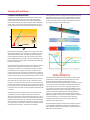
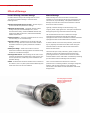
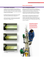
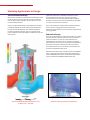
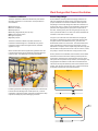
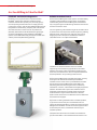
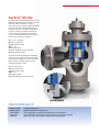
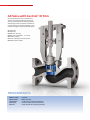
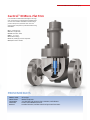
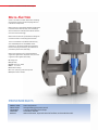
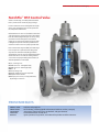
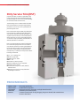
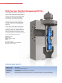
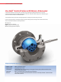
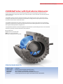
Fisher Cavitation-Control Technologies
®
Solutions to Cavitation Problems
2 | Fisher® Cavitation-Control Technologies
Control Valve Cavitation
Cavitation is a concern for plant operators and maintenance
personnel because it can reduce plant availability and
profitability. Cavitation not only decreases flow capability
through control valves, but it may also cause material damage,
excessive noise, and excessive vibration.
A wide range of Fisher® cavitation-control technologies
are available for clean and dirty service. Included in this
brochure are images of Fisher technologies with descriptions,
specifications, and proven results.
Hydrocarbon and Petrochemical Industries
Hydrocarbon and petrochemical industries are built on reliable
liquid process control. Typical fluids include: crude oil with
multiple chemical compounds and particulate, highly refined
single compounds such as butane, and complex intermediates.
These fluids are transported and processed in a variety of ways.
Applications are driven by pump, reaction, or vertical head.
In all cases, the process equipment must be correctly sized
and selected to attain the best loop control, minimize process
variability, and deliver the best process results.
Cavitation is an unintended occurrence in many of these
processes. Mixture hydrocarbons, such as crude oils, may have
less damage potential than a similar application on water,
but highly refined fluids, such as gasoline blends, can cavitate
with the same damage potential as water. Crude oils often
carry particulate that will plug the small flow passages in some
cavitation-control designs.
Supporting hydrocarbon and petrochemical industries with
cavitation solutions requires a broad range of valve designs
covering clean to dirty fluids, benign to very corrosive fluids,
and flow rates requiring NPS 1 to 48 and larger.
Power Industry
All power or process steam plants, whether traditional coal
fired, integrated gasification combined cycle, nuclear, or
combined cycle, have the potential to experience cavitation
and its related effects. This is due to the high-pressure water
and pressure drops experienced in applications such as boiler
feedwater startup, pump recirculation, and desuperheater
spraywater. The negative effects of cavitation in these
applications can be effectively combated by utilizing one of
the many Fisher technologies.
Special consideration should be given to the chemistry of
the water as well as the presence of particulate, which is
common in these applications. For example, the use of
R30006/CoCr-A in boiler feedwater may be acceptable
depending on the amount and type of amines present. The
use of anti-cavitation trims should be evaluated based on the
presence of particulate, weld slag, and magnetite. A variety of
trim styles, such as Fisher dirty service trims, are available to
prevent damaging cavitation while passing large particulate.
Process facilities don’t have to be limited by the damaging
effects of cavitation. Emerson Process Management provides
proven, engineered solutions for these applications utilizing
Fisher technologies.
Additional Industries
Process industries such as mining, pulp and paper, life
sciences, and food and beverage experience cavitation
challenges. These industries use steam for motive force or
process heating. Steam generation requires high-pressure
water and involves processes that can cavitate. Fluid control
applications may combine cavitation with: high viscosity,
multi-phase fluid; corrosion; or coking or plugging fluid.
Emerson Process Management has Fisher control valves for
all these challenges, which are similar to those shown in this
brochure but with variations in geometry and materials.
By utilizing local application engineers and experienced design
engineers, Emerson Process Management can deliver a custom
solution for your special application.
View an animation video on cavitation
at www.FisherSevereService.com.
Fisher® Cavitation-Control Technologies | 3
Science of Cavitation
Cavitation and Choked Flow
Q, GPM
Cavitation is a purely liquid flow phenomena—gases cannot
cavitate. Choked flow may occur as a result of cavitation.
Choked flow occurs when the normal relationship between
flow and increased pressure drop is broken. With choked flow,
an increase in pressure drop by decreasing the downstream
pressure does not result in more flow through the restriction.
As the pressure recovers, the vapor cavities implode, forming
high-speed, destructive microjets and localized shock waves.
Either of these mechanisms, when located near the material
surface, can cause severe damage to valve elements such as
the plug, seat, body, and associated pipe.
CHOKED
FLOW
RATE
CV
P CHOKED
P
Basic valve sizing equations imply that, for a given valve, flow
should continually increase by simply increasing the pressure
differential across the valve. In reality, the relationship given
by these equations holds true for only a limited range. As the
pressure differential is increased, a point is reached where the
flow increase stops. This condition of limited maximum flow is
known as choked flow.
Consider the simple restriction shown to the right. The pressure
of the liquid, P, is plotted as a function of the distance, X,
through the restriction. As a liquid passes through a reduced
cross-sectional area, velocity increases to a maximum and
pressure decreases to a minimum. As the flow exits, velocity is
restored to its original value while the pressure is only partially
restored, thus creating a pressure differential across the device.
There is a point along the flow path called the vena contracta,
where the flow area and pressure are at a minimum and the
velocity is at a maximum. When this point is reached, the local
pressure may drop to or below the vapor pressure of the liquid,
forming vapor cavities. The density of the liquid-vapor mixture
continues to decrease until the compressible choked flow limit
is reached.
The distance from the restriction to the vena contracta will
vary with the pressure conditions and type of restriction.
After the vena contracta, the liquid pressure will recover to or
below the downstream pressure. If the downstream pressure is
higher than the vapor pressure, the vapor cavities will collapse.
This is cavitation. If the downstream pressure stays at or below
the vapor pressure, the vapor cavities do not collapse and the
vapor expansion continues. This is known as flashing.
The model above depicts mean fluid pressure. Flow through
control valves causes significant deviations from the mean
pressure. Deviations include instantaneous pressure
fluctuations associated with fluid turbulence, and low pressures
in the cores of vortices and eddies associated with boundarylayer separation, free shear zones, stagnation regions, and
re-entrant zones. These explain some of the differences seen
between the textbook view represented by the blue line and
realistic computational fluid dynamics represented by the
yellow line. These phenomena can produce local pressures
significantly higher or lower than the mean pressure, sufficient
to initiate cavitation in very localized regions. Typically,
cavitation begins before the minimum mean pressure is
reduced to the vapor pressure.
Standard liquid sizing fully accounts for the capacity concern
associated with choked flow and prevents undersizing the
valve. Additional empirical information is required to predict
different levels of cavitation.
4 | Fisher® Cavitation-Control Technologies
Effects of Damage
Factors Affecting Cavitation Damage
Material Damage
Cavitation doesn’t always cause damage when it occurs.
The extent of cavitation damage is a function of the
following factors:
Physical damage to a control valve due to uncontrolled
cavitation is a concern because of the high maintenance cost,
inconvenience, unpredictability, and unplanned downtime.
Damage can consist of a mechanical and selective chemical
attack on the material surface.
n Intensity/magnitude of pressure drop – Greater drops in
pressure increase the potential for damage.
n
Materials of construction – Hardened materials reduce
damage. Examples include R30006/CoCr-A, nickelchromium-boron alloys, hardened S44004 stainless steel,
hardened S17400 stainless steel, and hardened S41000/
S41600 stainless steel.
n Time of exposure – The longer cavitation occurs in an area,
the more likely it is to result in damage.
Typically, cavitation damage is characterized by a very
irregular, pitted, rough appearance. Valve parts with extensive
damage may have large amounts of material missing.
The mechanical attack can occur in two forms: microjet
impingement and shockwave impingement. Microjet
impingement causes erosion of the material surface. Shockwave
impingement causes material deformation and failure.
n Quantity of flow – Cavitation issues generally scale with
flow rates. A larger flow rate means more fluid is available
to cavitate and there is a greater potential for cavitation
damage.
n
Valve/trim design – Fisher control valve trim can be
selected to combat the damaging effects of cavitation using
isolation or elimination techniques.
n
Leakage while closed – If seat leakage occurs when a valve
is closed, the liquid moves quickly from a high-pressure area
to a low-pressure area, which may result in cavitation and
potential damage.
n Fluid – Fluid behavior should be considered in trim selection.
For instance, water in a power plant behaves differently than
crude oil for the same service conditions.
A chemical attack occurs when the protective, passive oxide
layer is physically removed from the base metal during the
mechanical attack. The base material is left vulnerable to
further chemical attack.
The science of vapor cavity nucleation, growth, collapse, and
rebound is at the core of cavitation damage. Rather than
go through the science, the focus will be on how to reduce
cavitation effects. Further information is available by contacting
your local Emerson Process Management sales office.
There are several factors that determine a material’s
performance in a cavitating situation, including its toughness,
hardness, and corrosion resistance in the application
environment. These factors are discussed in the materials of
design section.
This valve plug has sustained
extensive cavitation damage.
It shows a complete loss of
seating surfaces.
Fisher® Cavitation-Control Technologies | 5
Emerson Innovation
Excessive Noise and Vibration
Fisher® Technology Development
Cavitation can cause unacceptable noise and vibration.
Although the noise associated with a cavitating liquid can be
quite high, it is usually a secondary concern when compared
to the material damage that can exist. Cavitation is frequently
described as sounding like gravel in a pipe, but the character of
cavitation noise can vary widely.
The Emerson Innovation Center for Fisher Technology in
Marshalltown, Iowa, USA, is home to the world’s largest flow
lab used to evaluate control valves. It incorporates flow testing
capabilities up to NPS 36 and 240 bar (3,500 psig). Final
control elements are tested in conformance to IEC and ISA
standards in real-world plant conditions to ensure production
reliability, efficiency, environmental compliance, and safety.
Damaging cavitation can take place without noise, and the
level of noise and vibration from a control valve may not
always coincide with the cavitation damage level.
Vibration resulting from cavitation may be more prevalent
than cavitation damage. It can affect the valve positioner,
linkage, tubing, and adjacent pipe.
Emerson engineers conduct tests that analyze cavitation,
materials, fatigue, wear, high and low temperatures, valve
actuators, valve instrumentation, seismic requirements,
reliability, loop variability, leakage, hydrostatic forces, gaskets,
seals, and control system compatibility. In the controlled lab
environment, special tests are commonly performed to answer
customers’ questions.
Emerson engineers conduct noise
and vibration tests on cavitating
applications in many different
ways. Transparent pipe allows
visualization of the cavitation
field. Cavitation demonstrations
can be arranged with your local
Emerson Process Management
sales office.
Normal, turbulent flow in a transparent pipe.
Cavitation and turbulent flow vary with pressure drops.
Note the variation in flow fields between this
image and the second image, despite identical
service conditions.
6 | Fisher® Cavitation-Control Technologies
Matching Applications to Design
Valve Selection and Design
When service conditions and the process loop design are fixed,
a control valve may have to operate at pressure conditions
that normally result in cavitation. In such instances, source
treatment will be needed.
Clearly, a single product design is not sufficient for the wide
variation of applications across multiple process industries.
Emerson Process Management uses multiple approaches
to address application-specific issues. A large selection of
Fisher cavitation-control technologies is utilized for clean and
dirty services.
Application experience, knowledge of cavitation science,
and the effect of valve size, type, trim style, geometry,
and materials are all critical to providing reliable solutions.
Standard or custom Fisher control valves with anti-cavitation
trim can be used to control cavitation.
Fisher anti-cavitation trim styles utilize multiple techniques
such as pressure staging, jet formation control, and
flowstream manipulation to control cavitation and prevent its
damaging effects.
Materials of Design
Since the standard materials used in valve bodies are relatively
soft, selection for cavitation resistance must rely on factors
other than hardness. In general, as the chromium and
molybdenum contents increase, the resistance to damage
from cavitation increases. Thus, the chromium-molybdenum
alloy steels have better resistance than the carbon steels,
and stainless steels have an even better resistance than the
chromium-molybdenum alloy steels.
Materials commonly used for cavitating services are R30006/
CoCr-A, nickel-chromium-boron alloys (solid and overlays),
hardened S44004 stainless steel, hardened S17400 stainless
steel, and hardened S41000/S41600 stainless steel.
Pressure distribution through Fisher Dirty Service Trim
in a NPS 16 easy-e™ valve body.
Detailed view of the flow pathlines through the trim.
Fisher® Cavitation-Control Technologies | 7
Plant Designs that Prevent Cavitation
Cavitation Coefficient
Process Loop Design
The Fisher cavitation coefficient indicates the potential for
damaging cavitation in a control valve. It is dependent on
several factors:
Flow conditions that will produce damaging cavitation can
often be avoided at the design phase of a project by giving
proper consideration to service conditions and the process
loop design. Process loop design can influence cavitation in a
control valve. Figure 1 shows a valve installation and pressure
plot where the majority of the pipe system is upstream of
the valve. Looking at the pressure along the pipe or loop, the
valve is positioned where P2 is close to Pv and the likelihood of
cavitation in the control valve is high.
n Valve/trim style
n Service conditions
n Fluid properties
n Intensity/magnitude of pressure drop
n Materials of construction
n Length of exposure
n Quantity of flow
The Fisher cavitation coefficient predicts the onset of
cavitation-related damage. It is available for every Fisher
cavitation-control product throughout its full, intended
application range.
Other vendors utilize similar application guidelines. The user
is cautioned to always use the guideline associated with the
chosen vendor. The coefficient is not interchangeable.
In Figure 2, the valve has been relocated so the majority of
the system is downstream. Now P2 associated with the valve
is higher and thus much different from Pv , therefore the
likelihood of cavitation is much lower. This demonstrates the
value of locating the valve to leverage the natural pressure
distribution in a system. These simple diagrams show only pipe
but the effect of all system elements—such as reactors, vessels,
and pumps—must be considered in a loop pressure review.
If valve placement is not flexible, flow resistance can be added
downstream of the control valve utilizing an orifice plate or a
second valve. Fluid pressures within the valve increase and it
will experience less pressure drop. However, this technique may
simply displace cavitation from the valve to the downstream
restriction and may not effectively control the cavitation in the
system. This may also increase valve size, as less pressure drop
is available to process the same amount of flow.
PRESSURE
Figure 1
P1
PVC
PV
Predicting the onset of damaging cavitation is an arduous task.
Emerson Process Management’s field experience, research
capabilities, and subject matter expertise in fluid behavior help
improve the ability to predict damaging cavitation.
Figure 2
P1
PRESSURE
P2
PVC
PV
P2
8 | Fisher® Cavitation-Control Technologies
Are You Willing to Take the Risk?
FIELDVUE™ Performance Diagnostics
Reliable Cavitation Control
Reliability is a key requirement for all process facilities.
FIELDVUE™ digital valve controllers installed on Fisher
cavitation-control valves protect your process by giving a
view of operating characteristics such as supply pressure,
control signal, friction, and seat load. FIELDVUE Performance
Diagnostics run continuously, analyzing valve and actuator
data while the valve remains in service. If problems are
detected, information can be directed to the appropriate
personnel automatically, when installed in a PlantWeb™
system. These notifications help you keep the control valve
and the process loop functioning optimally.
Emerson Process Management was a pioneer in understanding
cavitation-related problems in control valves. Through this
understanding, Emerson Process Management has lead the
way in engineering and manufacturing cavitation-control trims
that solve customers’ issues.
Correct engineering and manufacturing of anti-cavitation trims
is critical to their overall operation and life expectancy. Holding
tight tolerances, selecting correct materials, and correctly
staging the pressure drop can be the difference between
extended trim life or an unplanned shutdown.
Confidence in cavitation solutions relies on true OEM
engineering and manufacturing specifications. Non-OEM
solutions may appear to offer cost-effective solutions in the
short term, but introduce new risks of unexpected shutdowns
and lost production. Are you willing to take this risk?
Emerson Process Management provides the quality, accuracy,
and engineered solutions demanded by these difficult
cavitation services. Local service is provided before and after
the sale. Emerson Process Management sales offices are
backed by global manufacturing sites that can effectively
manufacture, measure, and assemble these highly-engineered
solutions. No matter where your Fisher cavitation-control
technology is manufactured, product quality remains the
constant that our engineers demand and our customers
deserve. Parts and services are available to minimize downtime
and maximize throughput.
If you have an existing installation with a cavitation problem,
or you want to ensure that your next installation will not
experience its damaging effects, contact your Emerson Process
Management sales office. You will receive the support needed
to accurately size, select, and install the solution to your
cavitation problem.
Comprehensive information on cavitation is available from
your local sales office or from www.FisherSevereService.com.
Fisher® Cavitation-Control Technologies | 9
Cavitrol™ III trim
is used for cavitating liquid applications in various
globe and angle valve bodies. Cavitrol™ III trim can
effectively eliminate cavitation damage.
The cage contains a multitude of specially shaped
holes; the hole shape reduces fluid turbulence.
In addition, the holes are radially aligned to flow
from one restriction to another. This action is
pressure staging, dividing the total drop into
smaller increments. Both features dissipate the
fluid pressure and prevent cavitation.
n 1, 2, 3, or 4-stage trim
n Globe or angle body
n ASME Class 300 - 2500
n NPS 1 - 24
n Flow-down design
n 276 bar (4000 psi) pressure drop limit
n ANSI/FCI Class V shutoff
The optional Protected Inside Seat technology,
shown right, has seating surfaces on the inside
tip of the valve plug and the radius in the groove
of the seat ring, so shutoff surfaces are not
exposed to potential erosion.
n 2, 3, or 4-stage trim
n Globe or angle body
n ASME Class 900 - 2500
n NPS 2 - 6
n Flow-down design
n 276 bar (4000 psi) pressure drop limit
PROVEN RESULTS
PRODUCTION:
APPLICATION:
CHALLENGE:
SOLUTION:
RESULTS:
Co-generation power.
Boiler feedwater drum level system.
Seat leakage due to cavitation and frequent trim replacement.
NPS 6 Fisher HPT valve with 4-stage Cavitrol III trim and Class V shutoff.
Operating time increased by 50% and control was improved.
10 | Fisher® Cavitation-Control Technologies
GX Valve with Cavitrol™ III Trim
lowers hydrodynamic noise and vibration by
utilizing a proprietary drilled-hole shape and
spacing. The special hole technology and flowdown design reduces and isolates cavitation to
prevent damage. Cavitrol III technology is used
without altering the integral GX bonnet design.
n 1-stage trim
n Globe body
n ASME Class 150, 300
n DN 25, 40, and 50 (NPS 1, 1½, and 2)
n Flow-down design
n 27.6 bar (400 psi) pressure drop limit
n ANSI/FCI Class V shutoff
PROVEN RESULTS
PRODUCTION:
APPLICATION:
CHALLENGE:
SOLUTION:
RESULTS:
Fertilizer.
Make-up water.
Control of low-intensity cavitation.
Fisher GX valve with Cavitrol III trim.
Long valve life in a compact package.
Fisher® Cavitation-Control Technologies | 11
Cavitrol™ III Micro-Flat Trim
is a combination of distinct technologies. The cage,
plug, and seat ring are designed and manufactured
as a unit. The benefit is cavitation control for high
pressure drops at very low flow rates. The trim
package also incorporates a protected seat for long
shutoff life.
n 2, 3, or 4-stage trim
n Globe or angle body
n ASME Class 300 - 2500
n NPS 1, 1½, and 2
n Flow-down design
n 241 bar (3500 psi) pressure drop limit
n ANSI/FCI Class V shutoff
PROVEN RESULTS
PRODUCTION:
APPLICATION:
CHALLENGE:
SOLUTION:
RESULTS:
Oil and gas.
Methanol injection.
Very low flow, high pressure drop, cavitation, and vibration.
Fisher Cavitrol III Micro-Flat trim.
Provided accurate, low-flow control and prevented cavitation.
12 | Fisher® Cavitation-Control Technologies
Micro-Flat Trim
utilizes a cavitation-control mechanism consisting
of special flow paths to prevent impingement on
critical trim components.
Micro-Flat trim is intended for low-flow applications
in the flow-down direction only. The trim design
does not eliminate cavitation but controls where it
occurs to minimize damage.
Micro-Flat trim features a protected seat design to
maximize seat life in cavitating environments.
The trim is available in hardened materials only,
such as R30006/CoCr-A and S44004. These
materials are needed to provide wear resistance
between the plug and seat ring. An outlet liner is
provided to protect the valve body.
Micro-Flat cavitation trim is recommended for
angle valve applications. In special cases, it can be
engineered into a globe valve body.
n 1-stage trim
n Angle body
n ASME Class 150 - 2500
n NPS 1, 1½, and 2
n Flow-down design
n 51.7 bar (750 psi) pressure drop limit
n ANSI/FCI Class V shutoff
PROVEN RESULTS
PRODUCTION:
APPLICATION:
CHALLENGE:
SOLUTION:
RESULTS:
Power and process.
Desuperheating spraywater control.
Low flow and high pressure drops.
Fisher Micro-Flat trim.
Reduced vibration, improved control of low flows, and extended trim life.
Fisher® Cavitation-Control Technologies | 13
NotchFlo™ DST Control Valve
utilizes a multi-stage, axial flow path where fluid
flow is parallel to the axis of the plug and cage.
Pressure reduction occurs throughout the length
of the plug. Individual stages are not exposed to
the full pressure differential.
NotchFlo DST trim uses a series of flow restrictions
and expansions to control the pressure drop of the
fluid. The notched plug allows up to 12 mm (½-inch)
particulate to flow through the trim without
plugging. The amount of pressure drop per stage
is designed to prevent cavitation problems and
minimize erosion issues on a properly sized valve.
Due to the need for tight shutoff, this multi-stage
trim incorporates a protected seat design that
separates the shutoff and throttling locations.
All significant pressure drops are taken downstream
of the valve seat. As a result, the seating surfaces
are not worn away by throttling control action, so
shutoff capabilities are extended.
n 3, 4, or 6-stage trim
n ASME Class 150 - 1500 globe body
n ASME Class 150 - 2500 angle body
n NPS 1 - 8
n Flow-up design only
n 290 bar (4200 psi) pressure drop limit
n ANSI/FCI Class V shutoff
n Ability to pass 12 mm (½-inch) particulate,
depending on valve size
PROVEN RESULTS
PRODUCTION:
APPLICATION:
CHALLENGE:
SOLUTION:
RESULTS:
Ethylene and propylene.
Re-circulating, cavitating liquid with entrained solids at 103 bar (1500 psi).
Seat erosion, noise levels up to 120 decibels, and pipe vibration.
Fisher NotchFlo DST control valve.
Quiet operation, long seat life, and reduced lost product and flare emissions.
14 | Fisher® Cavitation-Control Technologies
Dirty Service Trim (DST)
provides cavitation-control for applications with
entrained particulate that could potentially plug
the flow passages or cause severe erosion damage
to conventional anti-cavitation trim.
The DST design uses a combined axial and radial
flow path that features large openings allowing
particulate up to 19 mm (¾-inch) in diameter to
pass through the valve.
Due to the need for tight shutoff, this multi-stage
trim incorporates a protected seat design that
separates the shutoff and throttling locations. All
significant pressure drops are taken downstream
of the valve seat. As a result, the seating surfaces
are not worn away by throttling control action, so
shutoff capabilities are extended.
DST is an expanding flow area design. Each stage
has a successively larger flow area. The result is
very efficient operation, because typically 80% of
the pressure drop is taken prior to the final stage
where there is little danger of cavity formation.
Consequently, a relatively low inlet pressure to the
final stage is achieved.
n 2, 3, 4, 5, or 6-stage trim
n Globe or angle body
n ASME Class 150 - 2500
n NPS 1 - 24
n Flow-down or flow-up design
n 290 bar (4200 psi) pressure drop limit
n ANSI/FCI Class V shutoff
n Can be used in easy-e™, EH, EHA, EW, HP,
and HPA valves
n Ability to pass 19 mm (¾-inch) particulate
depending on valve size
PROVEN RESULTS
PRODUCTION:
APPLICATION:
CHALLENGE:
SOLUTION:
RESULTS:
Oil and gas production.
Produced water injection.
High pressure drop, particulate, and tight shutoff needed.
Fisher Dirty Service Trim (DST).
Cavitation control with no cage plugging, long-term shutoff, and extended time
between shutdowns.
Fisher® Cavitation-Control Technologies | 15
CAV4 Control Valve with Cavitrol™ IV trim
has an expanding flow area design. Each of the
Cavitrol IV trim stages has a successively larger flow
area. The result is very efficient operation because
more than 90 percent of the overall pressure drop is
taken in the initial stages where there is little danger
of cavity formation. Consequently, a relatively low
inlet pressure to the final stage is achieved.
Due to the need for tight shutoff, this multi-stage
trim incorporates a protected seat design that
separates the shutoff and throttling locations. All
significant pressure drops are taken downstream
of the valve seat. As a result, the seating surfaces
are not worn away by throttling control action, so
shutoff capabilities are extended.
n 3, 4, or 5-stage trim
n Angle body
n ASME Class 2500 - 4500
n NPS 2 - 10
n Flow-down design
n 552 bar (8000 psi) pressure drop limit
n ANSI/FCI Class V and VI shutoff
PROVEN RESULTS
PRODUCTION:
APPLICATION:
CHALLENGE:
SOLUTION:
RESULTS:
Coal-fired power plant.
Boiler feedwater recirculation service.
538 bar (7800 psi) pressure drop water at 204°C (400°F).
NPS 10 Fisher block-forged valve with 5-stage Cavitrol IV trim.
Withstood high pressure, prevented cavitation, and provided accurate control.
16 | Fisher® Cavitation-Control Technologies
Dirty Service Trim for Outgassing (DST-G)
is a multi-stage control valve trim design. It is used
in services where the fluid has dissolved gases
that are released from solution due to a reduction
in pressure. The fluid may also contain entrained
particulate. DST-G is mainly used in refining,
petrochemical, and oil and gas applications.
Outgassing can cause two types of damage.
One type is cavitation, as discussed previously.
The other is erosion from a rapidly expanding
flowstream.
The DST-G trim employs the basic design from
the standard DST trim, but utilizes a different
design for the lower cage. The DST-G lower cage
controls jet formation and discharge into the
body to prevent vibration and erosion. The trim
accomplishes all this while allowing large 6.35 mm
(¼-inch) particulate to pass through.
n Multi-stage trim
n Angle body
n ASME Class 150 - 2500
n NPS 1 - 12
n Flow-down design
n 175 bar (2500 psi) pressure drop limit
n ANSI/FCI Class V shutoff
PROVEN RESULTS
PRODUCTION:
APPLICATION:
CHALLENGE:
SOLUTION:
RESULTS:
Oil refinery.
Hot, low-pressure flash drum.
Outgassing, large particulate, and cavitation.
Fisher DST-G.
Reduced vibration, enabled long seat life, and provided reliable, long-lasting throughput.
Fisher® Cavitation-Control Technologies | 17
461 Sweep-Flo Angle Valve
is self cleaning with an expanded outlet. It is
typically used in the chemical and hydrocarbon
industries where cavitation control is required for
residual oils that experience coking, have high
particulate content and viscosity, and may outgas.
This cavitation-control valve construction consists
of carefully designed flow paths that control
impingement, and material selections aimed at
maximizing corrosion and erosion resistance.
For instance, trims such as S17400 stainless steel
in a variety of heat treatments, tungsten carbide,
R30006/CoCr-A, and others are common.
n Sweep-Flo angle body
n ASME Class 150 - 2500
n NPS 2x3, 3x4, 4x6, and 6x8
n Flow-down design
n ANSI/FCI Class V shutoff
PROVEN RESULTS
PRODUCTION:
APPLICATION:
CHALLENGE:
SOLUTION:
RESULTS:
Oil refinery.
Hot, high-pressure separator.
A cavitating, outgassing, viscous fluid.
Fisher 461 valve with 316 SST R30006/CoCr-A hardfaced trim.
Withstood high-pressure drop, outgassing, and cavitation issues plus provided
accurate control.
18 | Fisher® Cavitation-Control Technologies
Vee-Ball™ Control Valve with Rotary Attenuator
combines the efficiency of a rotary valve, with the energy absorbing capability of special trim, to provide
improved performance for demanding applications. The Fisher rotary attenuator design can be utilized in liquid
service to reduce cavitation and vibration effects.
The Vee-Ball with rotary attenuator has high application versatility and provides long service life.
Precise contouring of the V-notch ball provides an approximately equal percentage inherent flow characteristic,
which is optimal for most flow control applications.
n 1-stage trim
n ASME Class 150, 300, 600
n NPS 4, 6, 8, 10, 12, 14, 16, and 20
n 52 bar (750 psi) pressure drop limit
PROVEN RESULTS
PRODUCTION:
APPLICATION:
CHALLENGE:
SOLUTION:
RESULTS:
Water treatment process.
Greywater flow control.
Standard ball valve was cavitating, causing pipe vibration plus problems with the valvemounted instrumentation.
NPS 10 Vee-Ball control valve with rotary attenuator.
The rotary attenuator eliminated vibration and noise caused by vibration, and instrument
issues were resolved.
Fisher® Cavitation-Control Technologies | 19
V260B Ball Valve with Hydrodome Attenuator
provides improved performance for demanding applications such as pump bypass and pipeline take-off.
The attenuator trim is designed for liquid service to help eliminate or reduce cavitation and associated pipeline
noise and vibration.
The V260B is a full bore ball valve designed with features for optimized pressure, flow, and process control.
An integral, drilled attenuator controls noise and vibration from high pressure drop liquids. The splined shaft
connection to the actuator reduces lost motion.
The V260B with Hydrodome attenuator combines the efficiency of a rotary valve with the energy-dissipating
capability of a special trim to provide improved performance for demanding applications. The valve is available
with single and dual Hydrodome configurations.
The Hydrodome attenuator is active throughout the ball rotation for very demanding services or a characterized
attenuator (as shown) is used to match the service conditions.
n 1 or 2-stage trim
n ASME Class 150, 300, 600, 900
n NPS 8, 10, 12, 16, 20, and 24
n 103 bar (1500 psi) pressure drop limit
PROVEN RESULTS
PRODUCTION:
APPLICATION:
CHALLENGE:
SOLUTION:
RESULTS:
Crude oil.
Delivery valve for pipeline take-off location.
31 bar (450 psi), 120 decibels, and vibration.
NPS 12 Fisher V260 valve with Hydrodome attenuator.
Uninterrupted service for 8 years and reduced noise to 90 decibels.
© Fisher Controls International LLC 2011 All Rights Reserved.
Fisher, FIELDVUE, PlantWeb, Cavitrol, NotchFlo, and Vee-Ball are marks owned by one of the companies in
the Emerson Process Management business division of Emerson Electric Co. Emerson Process Management,
Emerson, and the Emerson logo are trademarks and service marks of Emerson Electric Co. All other marks are
the property of their respective owners.
Emerson Process Management
Marshalltown, Iowa 50158 USA
Sorocaba, 18087 Brazil
Chatham, Kent ME4 4QZ UK
Dubai, United Arab Emirates
Singapore 128461 Singapore
www.EmersonProcess.com/Fisher
D351912X012 / MX14 (H:) / Apr11
The contents of this publication are presented for informational purposes only, and while every effort has
been made to ensure their accuracy they are not to be construed as warranties or guarantees, express
or implied, regarding the products or services described herein or their use or applicability. All sales are
governed by our terms and conditions, which are available upon request. We reserve the right to modify
or improve the designs or specifications of such products at any time without notice. Neither Emerson,
Emerson Process Management, nor any of their affiliated entities assumes responsibility for the selection,
use, or maintenance of any product. Responsibility for proper selection, use, and maintenance of any
product remains solely with the purchaser and end user.