1
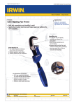
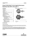
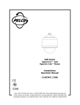
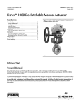
Instruction Manual
Form 5454
November 2007
M Series Actuator
M Series Manual Handwheel Gear Actuator
Contents
Introduction . . . . . . . . . . . . . . . . . . . . . . . . . . . . . . .
Scope of Manual . . . . . . . . . . . . . . . . . . . . . . . . .
Description . . . . . . . . . . . . . . . . . . . . . . . . . . . . . .
Specifications . . . . . . . . . . . . . . . . . . . . . . . . . . . .
Installation . . . . . . . . . . . . . . . . . . . . . . . . . . . . . . . .
Operation . . . . . . . . . . . . . . . . . . . . . . . . . . . . . . . . .
Maintenance . . . . . . . . . . . . . . . . . . . . . . . . . . . . . .
Lubrication . . . . . . . . . . . . . . . . . . . . . . . . . . . . . . .
Parts Ordering . . . . . . . . . . . . . . . . . . . . . . . . . . . . .
1
1
1
1
2
4
4
5
5
Introduction
Scope of Manual
This instruction manual includes installation,
operation, maintenance, and parts ordering
information for M Series manual handwheel gear
actuators. Refer to separate manuals for instructions
covering the valves used with these actuators.
Do not install, operate, or maintain an M Series
handwheel gear actuator without first D being fully
trained and qualified in valve, actuator, and
accessory installation, operation, and maintenance,
and D carefully reading and understanding the
contents of this manual. If you have any questions
about these instructions, contact your Emerson
Process Managementt sales office before
proceeding.
W4715-1 / IL
Figure 1. M Series Handwheel Gear Actuator
Specifications
Specifications for the M Series manual handwheel
gear actuators are shown in table 1.
Note
Description
Neither Emerson, Emerson Process
Management, nor any of their affiliated
entities assumes responsibility for the
selection, use and maintenance of any
product. Responsibility for the
selection, use, and maintenance of any
product remains with the purchaser
and end-user.
D500237X012
M Series handwheel gear actuators (figure 1) are
totally enclosed, weatherproof, worm gear actuators
for reliable manual operation with Type A11, A31A
and A41 High Performance Butterfly Valves. The M
actuator consists of a body housing, cover, worm
gear, input shaft, and handwheel. The housing is
grease packed.
www.Fisher.com
Instruction Manual
Form 5454
November 2007
M Series Actuator
Table 1. Specifications
Construction Materials
Actuator Sizes
See tables 2, 3 and 4
Housing and Cover: Cast iron
Worm: Steel
Valve Compatibility
Worm Gear: Manganese Bronze
J Accepts Type A11 valve square-end shafts
from 10.3 to 34.9 mm (13/32 to 1-3/8 inches),
keyed shafts from 38.1 to 44.5 mm (1-1/2 to 1-3/4
inches)(1)
J Accepts Type A31A valve keyed shafts from
44.5 to 57.2 mm (1-3/4 to 2-1/4 inches)
J Accepts Type A41 valve Double D shafts from
12.7 to 44.5 mm (1/2 to 1-3/4 inches)
Input Shaft: Steel (303 SST on request)
Handwheel: Cast Iron
Mounting Positions
See figure 2
Dimensions and Approximate Weights
See Bulletin 22.2:M
Maximum Torque Output
Options
See Bulletin 22.2:M
J Locking plates with padlock for fixed positioning
Handwheel Rotation
J Stops are typically set every 10_, but can be
special ordered with stops set up to 45_ from both
ends
Clockwise handwheel rotation closes the valve
(produces clockwise rotation of the valve shaft)
J Handwheel extensions
1. As an option, CL600 NPS 10 (with 1-1/2 inch keyed shaft) and NPS 12 (with 1-3/4 inch shaft) Type A11 valves require a keyed connection if being used with size 9KE or 10KE-6 actuators.
that must be taken to protect against
process media.
Installation
WARNING
To avoid personal injury or property
damage resulting from the sudden
release of pressure, do not install the
actuator where service conditions
could exceed the limits given in this
manual or on the appropriate
nameplates. Use pressure-relieving
devices as required by government or
accepted industry codes and good
engineering practices.
Always wear protective gloves,
clothing, and eyewear when
performing any installation operations
to avoid personal injury.
Check with your process or safety
engineer for any additional measures
2
If installing into an existing
application, also refer to the WARNING
at the beginning of the Maintenance
section in this instruction manual.
The M Series gear actuator is normally mounted on
a valve at the factory. However, the actuator can be
field mounted; it can be mounted in any position on
the Type A11 or A31A and it can be mounted in
positions 1 and 3 on the Type A41, as shown in
figure 2. Make clearance considerations before
mounting the actuator to determine the most suitable
mounting position.
The M Series actuator has a direct stab-on design.
Simply insert the valve shaft into the broached area
of the body housing. Then attach the mounting
bracket to the actuator, using the torques listed in
table 5, and attach the mounting bracket to the
valve.
Instruction Manual
Form 5454
November 2007
M Series Actuator
Table 2. M Series Gear Actuator for A11 (CL600)
ACTUATOR
SIZE
HANDWHEEL
DIAMETER,
INCHES
n
lb
NUMBER
OF
TURNS
TO
CLOSE(3)
NSm
LbfSin
1,000(4)
1KE
12
80
18
9.5
452
4,000
303
2,690(4)
1KE
12
209
47
9.5
452
4,000
643
765
5,700
6,780(4)
2KE
5KE
12
445
400
100
90
9.5
12.5
678
904
6,000
8,000
643
846
1349
1354
2144
3520
1354
2144
3520
5,700
7,500
11,960(4)
12,000
19,000
31,160(4)
12,000
19,000
31,160(4)
2KE
5KE
7KE
7KE
9KE
10KE-6
7KE
9KE
10KE-6
12
12
18
18
24
18
18
24
18
445
445
436
440
440
214
440
440
214
100
100
98
99
99
48
99
99
48
9.5
12.5
13.5
13.5
16
72
13.5
16
72
678
904
2,260
2,260
3,390
8,474
2,260
3,390
8,474
6,000
8,000
20,000
20,000
30,000
75,000
20,000
30,000
75,000
MAXIMUM
RECOMMENDED
TORQUE(1)
VALVE
SIZE, NPS
VALVE
SHAFT SIZE,
INCHES
nSm
lbSin
3
13/32
113
4
5/8
6
7/8
8
1
10
12
1-3/8
1-1/2
1-1/2
1-3/8
1-3/4
1-3/4
RIM FORCE(2)
MAXIMUM TORQUE
RATING OF
ACTUATOR
1. Maximum recommended torque for the valve/actuator combination is based on valve shaft rating, actuator rating and rim force.
2. Rim force required to produce Maximum recommended torque.
3. This column shows the number of times the handwheel must be turned to close the valve 90 degrees.
4. Shaft rating of the A11 valve.
Table 3. M Series Gear Actuator for A31A
VALVE
SIZE, NPS
VALVE
SHAFT
SIZE,
INCHES
MAXIMUM
RECOMMENDED
TORQUE(1)
nSm
ACTUATOR
SIZE
lbSin
HANDWHEEL
DIAMETER,
INCHES
n
lb
NUMBER
OF TURNS
TO
CLOSE(3)
445
445
418
445
445
512
440
449
133
440
440
156
440
516
100
100
94
100
100
115
99
101
30
99
99
35
99
116
RIM FORCE(2)
MAXIMUM TORQUE
RATING OF ACTUATOR
NSm
LbfSin
9.5
12.5
13.5
9.5
12.5
13.5
13.5
16
72
13.5
16
72
16
72
271
904
2,260
271
904
2,260
2,260
3,390
8,474
2,260
3,390
8,474
3,390
8,474
6,000
8,000
20,000
6,000
8,000
20,000
20,000
30,000
75,000
20,000
30,000
75,000
30,000
75,000
CL150
14
1-3/16
16
1-1/4
18
1-1/2
20
1-3/4
24
2-1/4
644
847
1287
644
847
1,579
1356
2188
2188
1356
2147
2555
2147
8,474
5,700
7,500
11,390(4)
5,700
7,500
13,970(4)
12,000
19,370(4)
19,370
12,000
19,000
22,620(4)
19,000
75,000
2KE
5KE
7KE
2KE
5KE
7KE
7KE
9KE
10KE-6
7KE
9KE
10KE-6
9KE
10KE-6
12
12
18
12
12
18
18
24
18
18
24
18
24
18
12,000
22,620(4)
7KE
9KE
18
24
440
525
99
118
13.5
16
2,260
3,390
20,000
30,000
CL300
14
1-3/4
1356
2555
16
1-3/4
1356
2555
12,000
22,620(4)
7KE
9KE
18
24
440
525
99
118
13.5
16
2,260
3,390
20,000
30,000
18
2-1/4
2147
6,985
19,000
61,830(4)
9KE
10KE-6
24
18
440
423
99
95
16
72
3,390
8,474
30,000
75,000
20
2-3/4
2147
8474
19,000
75,000
9KE
10KE-6
24
18
440
516
99
116
16
72
3,390
8,474
30,000
75,000
24
2-3/4
8474
75,000
10KE-6
18
516
116
72
8,474
75,000
1. Maximum recommended torque for the valve/actuator combination is based on valve shaft rating, actuator rating and rim force.
2. Rim force required to produce Maximum recommended torque.
3. This column shows the number of times the handwheel must be turned to close the valve 90 degrees.
4. Shaft rating of the A31A valve.
3
Instruction Manual
Form 5454
November 2007
M Series Actuator
Table 4. M Series Gear Actuator for A41
VALVE
SHAFT
SIZE
SIZE,
INCHES
ACTUATOR
SIZE
nSm
1/2
0KE/D1
58
5/8
0KE/D2
3/4
0KE/D3
RIM FORCE(1)
lbSin
HANDWHEEL
DIAMETER,
INCHES
n
lb
515
8
441
21
138
1,230
8
227
51
240
2,120
8
391
88
SHAFT RATING
1
2KE/D4
468
4,140
12
325
73
1-1/4
6KE/D5
1,110
9,820
24
365
82
1-1/2
6KE/D6
1,356
12,000
24
445
100
1-3/4
9KE/D7
2,658
23,520
36
365
82
NUMBER OF
TURNS TO
CLOSE(2)
MAXIMUM TORQUE
RATING OF ACTUATOR
NSm
LbfSin
6
271
2,400
9.5
678
6,000
10
1 356
1,356
12 000
12,000
16
3,390
30,000
1. Rim force required to produce shaft rating torque.
2. This column shows the number of times the handwheel must be turned to close the valve 90 degrees.
Table 5. M Series Mounting Plate to Gearbox
Type M Actuator
Bolt Size
Bolt Torque nSm
Bolt Torque lbSf
A11 and A31A Compatible
1KE
1/2
91
67
2KE
1/2
91
67
5KE
1/2
91
67
7KE
5/8
163
120
9KE
5/8
163
120
10KE-6
5/8
163
120
A41 Compatible
0KE/D1
5/16
22
16.5
0KE/D2
5/16
22
16.5
0KE/D3
5/16
22
16.5
2KE/D4
3/8
39
29
6KE/D5
3/8
39
29
6KE/D6
5/8
163
120
9KE/D7
3/4
258
190
Operation
Maintenance
After the actuator and control valve assembly are
installed, the manual actuator is ready for operation.
CAUTION
Applying too much torque to the
actuator and valve parts could cause
damage to the parts. To avoid such
damage, do not exceed the rim force
listed in table 2, 3 and 4 or any other
torque limitation of internal valve
parts. Also, do not use wrenches or
other devices on the handwheel or
handwheel shaft to increase operating
force.
4
WARNING
Avoid personal injury from sudden
release of process pressure. Before
performing any maintenance
operations:
D Always wear protective gloves,
clothing, and eyewear when
performing any maintenance
operations to avoid personal injury.
D Disconnect any operating lines
providing air pressure, electric power,
or a control signal to the actuator. Be
sure the actuator cannot suddenly
open or close the valve.
D Use bypass valves or completely
shut off the process to isolate the
Instruction Manual
Form 5454
November 2007
M Series Actuator
valve from process pressure. Relieve
process pressure on both sides of the
valve. Drain the process media from
both sides of the valve.
1. Isolate the control valve from the line pressure,
release pressure from both sides of the valve body,
and drain the process media from both sides of the
valve.
D Vent the power actuator loading
pressure and relieve any actuator
spring precompression.
2. Remove the cap screws that secure the gearbox
cover plate and remove the gearbox cover plate.
D Use lock-out procedures to be
sure that the above measures stay in
effect while you work on the
equipment.
D The valve packing box may
contain process fluids that are
pressurized, even when the valve has
been removed from the pipeline.
Process fluids may spray out under
pressure when removing the packing
hardware or packing rings, or when
loosening the packing box pipe plug.
D Check with your process or safety
engineer for any additional measures
that must be taken to protect against
process media.
If the rim force required to rotate the handwheel
exceeds the rim force listed in table 2, 3, or 4, check
for the following conditions:
D Insufficient lubrication
D Seized actuator parts
D Excessive pressure drop across the valve
D Obstruction to the valve disc rotation
If the manual actuator does not seem to control the
process fluid, the worm or drive sleeve gear teeth
may be broken, the handwheel pin may be sheared,
or the valve parts may be broken. Purchase a
replacement manual actuator if necessary. Refer to
the valve instruction manual if valve maintenance is
needed.
3. Coat the worm, the drive sleeve gear teeth, and
the bearing surfaces of the gearbox housing and
worm with a quality gear lubricant.
4. Replace the cover plate and cap screws using
the bolt torques listed in table 5.
5. Replace the manual actuator on the valve. Adjust
the actuator travel stop to limit the open and closed
positions of the valve disc following the steps in the
appropriate valve instruction manual.
Parts Ordering
When corresponding with your Emerson Process
Management sales office, indicate the size of the M
Series actuator. The size is stamped on the gearbox.
You should also provide the serial number of the
valve.
WARNING
Use only genuine Fisherr replacement
parts. Components that are not
supplied by Emerson Process
Management should not, under any
circumstances, be used in any Fisher
valve, because they will void your
warranty, might adversely affect the
performance of the valve, and could
give rise to personal injury and
property damage.
Note
Lubrication
The interior parts of the M Series actuator should be
lubricated on a regular schedule with a quality gear
lubricant. The interior parts should also be lubricated
whenever difficulty in handwheel rotation indicates a
need for lubrication.
Neither Emerson, Emerson Process
Management, nor any of their affiliated
entities assumes responsibility for the
selection, use and maintenance of any
product. Responsibility for the
selection, use, and maintenance of any
product remains with the purchaser
and end-user.
5
Instruction Manual
Form 5454
November 2007
M Series Actuator
POSITION 1
VALVE BODY
FLOW DIRECTION
FOR RIGHT-HAND
MOUNTING
POSITION 2
FLOW DIRECTION
FOR LEFT-HAND
MOUNTING
POSITION 4
30B0668-A
A7133 / IL
POSITION 3
NOTE:
ONLY POSITIONS 1 AND 3 ARE APPLICABLE TO TYPE A41.
Figure 2. Available Mounting Positions
6
Instruction Manual
Form 5454
November 2007
M Series Actuator
GEAR BOX
A7139 / IL
MOUNTING BRACKET
Figure 3. Typical M Series Assembly
7
Instruction Manual
Form 5454
November 2007
M Series Actuator
Fisher is a mark owned by Fisher Controls International LLC, a member of the Emerson Process Management business division of Emerson
Electric Co. Emerson Process Management, Emerson, and the Emerson logo are trademarks and service marks of Emerson Electric Co.
All other marks are the property of their respective owners.
The contents of this publication are presented for informational purposes only, and while every effort has been made to ensure their accuracy, they are
not to be construed as warranties or guarantees, express or implied, regarding the products or services described herein or their use or applicability.
We reserve the right to modify or improve the designs or specifications of such products at any time without notice.
Neither Emerson, Emerson Process Management, nor any of their affiliated entities assumes responsibility for the selection, use and
maintenance of any product. Responsibility for the selection, use and maintenance of any product remains with the purchaser and end-user.
Emerson Process Management
Marshalltown, Iowa 50158 USA
Cernay 68700 France
Sao Paulo 05424 Brazil
Singapore 128461
www.Fisher.com
8
EFisher
Controls International LLC 1998, 2007; All Rights Reserved
Printed in USA