1
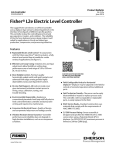
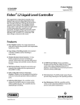
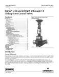
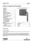
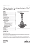
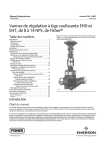
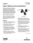
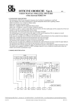
Instruction Manual Supplement
L2, L2e, and L2sj Controller
D103405X012
April 2013
Dimensions for NPS 2 CL150 through 1500
Slip‐On Flange Connections
Supplement to Fisherr L2, L2e, and L2sj Level Controller
Instruction Manuals
This supplement contains dimensions for NPS 2 CL150 through 1500 slip‐on flange connections for L2, L2e, and L2sj
level controllers.
Refer to the Maintenance section of the appropriate instruction manual for instructions on removing the sensor from
the controller, and disassembly of the sensor connector.
Refer to the appropriate instruction manual for all other information regarding the L2, L2e, or L2sj level controller.
D L2 dimensions—refer to figure 2 and table 1
D L2e dimensions—refer to figure 3 and table 2
D L2sj dimensions—refer to figure 4 and table 3
www.Fisher.com
Instruction Manual Supplement
L2, L2e, and L2sj Controller
D103405X012
April 2013
Flange Orientation
Orient the controller so that the case is level. See figure 1 for the proper sensor orientation for flange welding.
WARNING
To maintain code/standard compliance, weld fabrication must meet the requirements of AS ME Section IX. Failure to meet
these requirement could result in personal injury and/or property damage.
WARNING
To maintain compliance with NACE MR0175, weld fabrication must meet the requirements of NACE MR0175, paragraph 5.3.
Failure to meet these requirements could result in personal injury and/or property damage.
Note
Slip-on flanges are not supplied with the L2, L2e, or L2sj level controller. Contact your Emerson Process Management sales office
for information on obtaining a slip-on flange construction.
Figure 1. Sensor Orientation for Slip‐On Flange Mounting
FLANGE FACE
FLANGE
0.25
45_ $2.5_
22.5_$2.5_
8.64
(0.34)
0.63
A
A
A
A
2
1
OR HUB
WIDTH
CONNECTION
3
FLANGE ASSEMBLY
WITH 4 HOLE FLANGE
NOTE RELATION
OF TABS TO THE
BOLT PATTERN
FLANGE ASSEMBLY
WITH 8 HOLE FLANGE
SECTION A‐A
34B5013‐C
1
CONNECTION
SHOULDER TO BOTTOM ON FLANGE HUB EXCEPT WHEN
END‐TO‐FLANGE FACE IS LESS THAN 8.64 mm (0.34 INCH)
2
DIMENSION
ONLY APPLIES WHEN CONNECTION CAN BE INSERTED
SUCH THAT CONNECTION END‐TO‐FLANGE CONNECTION IS LESS THAN
8.64 mm (0.34 INCH)
CONNECTION
USED FOR ORIENTATION
3
2
mm
(INCH)
Instruction Manual Supplement
D103405X012
L2, L2e, and L2sj Controller
April 2013
Related Documents
D Bulletin 34.2:L2—Fisher L2 Liquid Level Controller (D103034X012)
D Fisher L2 Liquid Level Controller Instruction Manual (D103032X012)
D Bulletin 34.2:L2e—Fisher L2 Electric Level Controller (D103532X012)
D Fisher L2e Electric Level Controller Instruction Manual (D103531X012)
D Bulletin 34.2:L2sj—Fisher L2sj Low Emission Liquid Level Controller (D103229X012)
D Fisher L2sj Low Emission Liquid Level Controller Instruction Manual (D103216X012)
3
Instruction Manual Supplement
L2, L2e, and L2sj Controller
D103405X012
April 2013
Figure 2. Fisher L2 Liquid Level Controller—Dimensions with Slip‐On Flange
(Refer to Table 1 for Dimensions A, B, and F)
1/4‐18 NPT
OUTPUT CONN
D
1
2
3
248
(9.75)
B
A
155
(6.12)
1
2
302
(11.88)
F
2
48
(1.88)
j
191
(7.50)
2
2
302
(11.88)
318
(12.50)
ANSI FLANGE
14B8855‐A
j 48
1/4‐18 NPT
SUPPLY CONN
105
(4.12)
FLANGED CONNECTION
(1.88)
B
A
1
F
14B8856‐A
2
WELD PREPARATION FOR
SLIP‐ON CONNECTIONS
NOTES:
1
DIMENSIONS
A AND D INCLUDE ONE STANDARD 6‐INCH (152 mm) EXTENSION. CONTACT YOUR EMERSON
PROCESS MANAGEMENT SALES OFFICE FOR OPTIONAL EXTENSION LENGTHS.
2
DIMENSIONS
VALID WITH STANDARD DISPLACERS ONLY
DIMENSION
D IS EQUAL TO DIMENSION F PLUS 302 mm (11.88 INCH)
3
4
mm
(INCH)
Instruction Manual Supplement
L2, L2e, and L2sj Controller
D103405X012
April 2013
Table 1. Fisher L2 Liquid Level Controller—Dimension A, B, and F (see figure 2)
SIZE AND RATING
DIMENSIONS A, B, AND F
A
B
F
A
mm
2
3x2
4x2
6x2
NPS 2 slip-on
Connection
B
F
Inches
CL150 RF
326
202
277
12.85
7.96
10.90
CL300 RF
326
202
277
12.85
7.96
10.90
CL600 RF
320
209
270
12.58
8.23
10.63
CL600 RTJ
318
211
268
12.52
8.29
10.57
CL900/1500 RF
299
230
249
11.77
9.04
9.82
CL900/1500 RTJ
297
231
248
11.71
9.10
9.76
CL150 RF
326
202
277
12.85
7.96
10.90
CL300 RF
321
207
272
12.65
8.17
10.70
CL600 RF
312
217
262
12.27
8.54
10.32
CL600 RTJ
310
219
261
12.21
8.60
10.26
CL900 RF
296
233
246
11.65
9.17
9.70
CL900 RTJ
294
234
245
11.58
9.23
9.63
CL1500 FR
286
242
237
11.27
9.54
9.32
CL1500 RTJ
285
244
235
11.20
9.61
9.25
CL150 RF
326
202
277
12.85
7.96
10.90
CL300 RF
316
212
267
12.46
8.35
10.51
CL600 RF
304
225
254
11.96
8.85
10.01
CL600 RTJ
302
226
253
11.90
8.91
9.95
CL900 RF
296
233
246
11.65
9.17
9.70
CL900 RTJ
294
234
245
11.58
9.23
9.63
CL1500 RF
277
252
227
10.90
9.92
8.95
CL1500 RTJ
275
253
226
10.83
9.98
8.88
CL150 RF
324
204
275
12.77
8.04
10.82
CL300 RF
310
219
261
12.21
8.60
10.26
CL600 RF
292
236
243
11.52
9.30
9.57
CL600 RTJ
291
238
241
11.45
9.36
9.50
CL900 RF
272
257
222
10.71
10.10
8.76
CL900 RTJ
270
258
221
10.64
10.17
8.69
CL1500 RF
242
287
192
9.52
11.29
7.57
CL1500 RTJ
239
290
189
9.40
11.42
7.45
Weld preparation
335
194
285
13.19
7.62
11.24
5
Instruction Manual Supplement
L2, L2e, and L2sj Controller
D103405X012
April 2013
Figure 3. Fisher L2e Electric Level Controller—Dimensions with Slip‐On Flange
(Refer to Table 2 for Dimensions A, B, and F)
1
2
3
216
(8.51)
1
302
(11.88)
j
2
1
2
48
(1.88)
149
(5.87)
303 2
(11.92)
302 2
(11.88)
88
(3.46)
GG13010-A
j 48
142
(5.60)
FLANGED CONNECTION
(1.88)
1
F
2
GG13009-A
WELD PREPARATION FOR
SLIP‐ON CONNECTIONS
NOTES:
1
DIMENSIONS
A AND D INCLUDE ONE STANDARD 6‐INCH (152 mm) EXTENSION. CONTACT YOUR EMERSON
PROCESS MANAGEMENT SALES OFFICE FOR OPTIONAL EXTENSION LENGTHS.
2
DIMENSIONS
VALID WITH STANDARD DISPLACERS ONLY
DIMENSION
D IS EQUAL TO DIMENSION F PLUS 302 mm (11.88 INCH)
3
6
mm
(INCH)
Instruction Manual Supplement
L2, L2e, and L2sj Controller
D103405X012
April 2013
Table 2. Fisher L2e Electric Level Controller—Dimension A, B, and F (see figure 3)
SIZE AND RATING
DIMENSIONS A, B, AND F
A
B
F
A
mm
2
3x2
4x2
6x2
NPS 2 slip-on
Connection
B
F
Inches
CL150 RF
326
200
277
12.85
7.86
10.90
CL300 RF
326
200
277
12.85
7.86
10.90
CL600 RF
320
207
270
12.58
8.13
10.63
CL600 RTJ
318
208
268
12.52
8.19
10.57
CL900/1500 RF
299
227
249
11.77
8.94
9.82
CL900/1500 RTJ
297
229
248
11.71
9.00
9.76
CL150 RF
326
200
277
12.85
7.86
10.90
CL300 RF
321
205
272
12.65
8.07
10.70
CL600 RF
312
214
262
12.27
8.44
10.32
CL600 RTJ
310
216
261
12.21
8.50
10.26
CL900 RF
296
230
246
11.65
9.07
9.70
CL900 RTJ
294
232
245
11.58
9.13
9.63
CL1500 FR
286
240
237
11.27
9.44
9.32
CL1500 RTJ
285
242
235
11.20
9.51
9.25
CL150 RF
326
200
277
12.85
7.86
10.90
CL300 RF
316
210
267
12.46
8.25
10.51
CL600 RF
304
222
254
11.96
8.75
10.01
CL600 RTJ
302
224
253
11.90
8.81
9.95
CL900 RF
296
230
246
11.65
9.07
9.70
CL900 RTJ
294
232
245
11.58
9.13
9.63
CL1500 RF
277
249
227
10.90
9.82
8.95
CL1500 RTJ
275
251
226
10.83
9.88
8.88
CL150 RF
324
202
275
12.77
7.94
10.82
CL300 RF
310
216
261
12.21
8.50
10.26
CL600 RF
292
234
243
11.52
9.20
9.57
CL600 RTJ
291
235
241
11.45
9.26
9.50
CL900 RF
272
254
222
10.71
10.00
8.76
CL900 RTJ
270
256
221
10.64
10.07
8.69
CL1500 RF
242
284
192
9.52
11.19
7.57
CL1500 RTJ
239
288
189
9.40
11.32
7.45
Weld preparation
335
191
285
13.19
7.52
11.24
7
Instruction Manual Supplement
L2, L2e, and L2sj Controller
D103405X012
April 2013
Figure 4. Fisher L2sj Liquid Level Controller—Dimensions with Slip‐On Flange
(Refer to Table 3 for Dimensions A, B, and F)
1/4‐18 NPT
OUTPUT CONN
D
1
2
3
248
(9.75)
B
A
155
(6.12)
1
2
152.4
(6.00)
F
2
76.2
(3.00)
2
191
(7.50)
172.1
(6.78) 2
152.4
(6.00)
ANSI
FLANGE
1/4‐18 NPT
SUPPLY CONN
105
(4.12)
76.2
(3.00)
FLANGED CONNECTION
B
A
1
F
14B8856‐A
2
WELD PREPARATION FOR
SLIP‐ON CONNECTIONS
NOTES:
1
DIMENSIONS
A AND D INCLUDE ONE STANDARD 3‐INCH (76.2 mm) EXTENSION. CONTACT YOUR EMERSON PROCESS
MANAGEMENT SALES OFFICE FOR OPTIONAL EXTENSION LENGTHS.
2
DIMENSION VALID WITH STANDARD DISPLACERS ONLY
DIMENSION
D IS EQUAL TO DIMENSION F PLUS 152.4 mm (6.00 INCH)
3
8
mm
(INCH)
Instruction Manual Supplement
L2, L2e, and L2sj Controller
D103405X012
April 2013
Table 3. Fisher L2sj Liquid Level Controller—Dimension A, B, and F (see figure 4)
SIZE AND RATING
DIMENSIONS A, B, AND F
A
B
F
A
mm
2
3x2
4x2
6x2
NPS 2 slip-on
Connection
B
F
Inches
CL150 RF
250
202
201
9.85
7.96
7.90
CL300 RF
250
202
201
9.85
7.96
7.90
CL600 RF
243
209
194
9.58
8.23
7.63
CL600 RTJ
242
211
192
9.52
8.29
7.57
CL900/1500 RF
223
230
173
8.77
9.04
6.82
CL900/1500 RTJ
221
231
172
8.71
9.10
6.76
CL150 RF
250
202
201
9.85
7.96
7.90
CL300 RF
245
207
195
9.65
8.17
7.70
CL600 RF
235
217
186
9.27
8.54
7.32
CL600 RTJ
234
219
184
9.21
8.60
7.26
CL900 RF
220
233
170
8.65
9.17
6.70
CL900 RTJ
218
234
168
8.58
9.23
6.63
CL1500 FR
210
242
161
8.27
9.54
6.32
CL1500 RTJ
208
244
159
8.20
9.61
6.25
CL150 RF
250
202
201
9.85
7.96
7.90
CL300 RF
240
212
191
9.46
8.35
7.51
CL600 RF
228
225
178
8.96
8.85
7.01
CL600 RTJ
226
226
177
8.90
8.91
6.95
CL900 RF
220
233
170
8.65
9.17
6.70
CL900 RTJ
218
234
168
8.58
9.23
6.63
CL1500 RF
201
252
151
7.90
9.92
5.95
CL1500 RTJ
199
253
149
7.83
9.98
5.88
CL150 RF
248
204
199
9.77
8.04
7.82
CL300 RF
234
219
184
9.21
8.60
7.26
CL600 RF
216
236
167
8.52
9.30
6.57
CL600 RTJ
215
238
165
8.45
9.36
6.50
CL900 RF
196
257
146
7.71
10.10
5.76
CL900 RTJ
194
258
145
7.64
10.17
5.69
CL1500 RF
166
287
116
6.52
11.29
4.57
CL1500 RTJ
162
290
113
6.40
11.42
4.45
Weld preparation
259
194
209
10.19
7.62
8.24
9
L2, L2e, and L2sj Controller
April 2013
Instruction Manual Supplement
D103405X012
Neither Emerson, Emerson Process Management, nor any of their affiliated entities assumes responsibility for the selection, use or maintenance of any product.
Responsibility for proper selection, use, and maintenance of any product remains solely with the purchaser and end user.
Fisher is a mark owned by one of the companies in the Emerson Process Management business division of Emerson Electric Co. Emerson Process
Management, Emerson, and the Emerson logo are trademarks and service marks of Emerson Electric Co. All other marks are the property of their respective
owners.
The contents of this publication are presented for informational purposes only, and while every effort has been made to ensure their accuracy, they are not
to be construed as warranties or guarantees, express or implied, regarding the products or services described herein or their use or applicability. All sales are
governed by our terms and conditions, which are available upon request. We reserve the right to modify or improve the designs or specifications of such
products at any time without notice.
Emerson Process Management
Marshalltown, Iowa 50158 USA
Sorocaba, 18087 Brazil
Chatham, Kent ME4 4QZ UK
Dubai, United Arab Emirates
Singapore 128461 Singapore
www.Fisher.com
102009, 2013 Fisher Controls International LLC. All rights reserved.
E