1
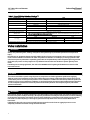
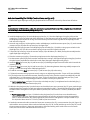
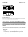
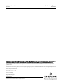
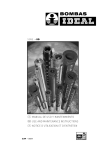
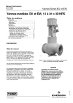
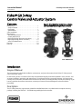
Instruction Manual GX 3-Way Valve and Actuator D103312X012 August 2011 Fisherr GX 3-Way Control Valve and Actuator System Contents Introduction . . . . . . . . . . . . . . . . . . . . . . . . . . . . . . . . . 1 Scope of Manual . . . . . . . . . . . . . . . . . . . . . . . . . . . . . 1 Description . . . . . . . . . . . . . . . . . . . . . . . . . . . . . . . . . 1 Specifications . . . . . . . . . . . . . . . . . . . . . . . . . . . . . . . 2 Valve Installation . . . . . . . . . . . . . . . . . . . . . . . . . . . . . 2 Maintenance . . . . . . . . . . . . . . . . . . . . . . . . . . . . . . . . . 3 Actuator Maintenance . . . . . . . . . . . . . . . . . . . . . . . . 5 Packing Maintenance . . . . . . . . . . . . . . . . . . . . . . . . . 9 Replacing Packing (Pneumatic Actuators) . . . . . . . . 9 Replacing Packing (Electric Actuators) . . . . . . . . . . 12 Valve Trim Maintenance . . . . . . . . . . . . . . . . . . . . . 15 Parts Kits . . . . . . . . . . . . . . . . . . . . . . . . . . . . . . . . . . . 19 Parts List . . . . . . . . . . . . . . . . . . . . . . . . . . . . . . . . . . . 20 Figure 1. Fisher GX 3-Way Control Valve, Actuator, and FIELDVUE DVC2000 Digital Valve Controller W9557 GX 3-WAY X0218 GX 3-WAY HIGH-TEMPERATURE Introduction Scope of Manual This instruction manual includes installation, maintenance, and parts information for the Fisher GX 3-Way control valve and actuator system. Do not install, operate, or maintain a GX 3-Way valve without being fully trained and qualified in valve, actuator, and accessory installation, operation, and maintenance. To avoid personal injury or property damage, it is important to carefully read, understand, and follow all the contents of this manual, including all safety cautions and warnings. If you have any questions about these instructions, contact your Emerson Process Management sales office before proceeding. Description The GX 3-Way meets the requirements of both EN and ASME standards. It is available with a complete accessory package, including the FIELDVUEt DVC2000 integrated digital valve controller. www.Fisher.com Instruction Manual GX 3-Way Valve and Actuator August 2011 D103312X012 Table 1. Fisher GX 3-Way Valve Specifications(1) Specifications EN ASME Valve Body Sizes DN 25, 40, 50, 80, 100 NPS 1, 1-1/2, 2, 3, 4 Pressure Rating PN 10 / 16 / 25 / 40 per EN 1092-1 CL150 / 300 per ASME B16.34 End Connections Flanged raised face per EN 1092-1 Flanged raised face per ASME B16.5 Valve Body Materials Bonnet Materials 1.0619 steel ASME SA216 WCC steel 1.4409 stainless steel ASME SA351 CF3M stainless steel 1.4409 stainless steel / CoCr-A ASME SA351 CF3M SST / CoCr-A Face-to-Face Dimensions Based on ISA 75.08.01, see bulletin 51.1:GX 3-Way for details Shutoff per IEC 60534-4 and ANSI/FCI 70-2 Metal seat - Class IV (standard) Side port common high temperature construction: Metal seat - Class IV for bottom seat, Class II for upper seat Flow Direction Trim Style Converging and Diverging Type Plug Style Type Side-Port Common All sizes Unbalanced Port-Guided Bottom-Port Common All sizes Balanced Cage-Guided 1. Stainless steel valve body is recommended for steam service when the high temperature (HT) construction is selected. Valve Installation WARNING Always wear protective gloves, clothing, and eyewear when performing any installation operations to avoid personal injury. Personal injury or equipment damage caused by sudden release of pressure or bursting of pressure retaining parts might result if service conditions exceed those for which the product was intended. To avoid injury or damage, provide a relief valve for over pressure protection as required by government or accepted industry codes and good engineering practices. Check with your process or safety engineer for any additional measures that must be taken to protect against process media. If installing into an existing application, also refer to the WARNING at the beginning of the Maintenance section in this instruction manual. CAUTION This valve is intended for a specific range of pressures, temperatures and other application specifications. Applying different pressure and temperatures to the valve could result in parts damage, malfunction of the control valve or loss of control of the process. Do not expose this product to service conditions or variables other than those for which the product was intended. If you are not sure what these conditions are you should contact your Emerson Process Management sales office for more complete specifications. Provide the product serial number (shown on the nameplate, figure 2) and all other pertinent information. WARNING If you move or work on an actuator installed on a valve with loading pressure applied, keep your hands and tools away from the stem travel path to avoid personal injury. Be especially careful when removing the stem connector to release all loading on the actuator stem whether it be from air pressure on the diaphragm or compression in the actuator springs. Likewise take similar care when adjusting or removing any optional travel stop. Refer to the relevant actuator Maintenance Instructions. If hoisting the valve take care to prevent people from being injured in case the hoist or rigging slips. Be sure to use adequately sized hoists and chains or slings to handle the valve. 2 Instruction Manual GX 3-Way Valve and Actuator D103312X012 August 2011 Figure 2. Fisher GX 3-Way Nameplate (Key 35) ELECTRIC ACTUATOR GE35409-C GG12218-A 1. Before installing the valve, inspect it to be certain that the valve body cavity is free of all foreign material. Clean out all pipelines to remove scale, welding slag and other foreign material. 2. The control valve assembly may be installed in any orientation unless limited by seismic criteria. However, the normal method is with the actuator vertical above the valve. Flow through the valve must be in the direction indicated by the flow arrow nameplate on the valve. See figures 3 and 4. 3. Use accepted piping practices when installing the valve in the pipeline. Use a suitable gasket between the valve and the pipeline flanges. 4. If continuous operation is required during inspection or maintenance, install isolating valves on either side of the control valve with a bypass valve to control the flow while the control valve is receiving maintenance. WARNING Personal injury could result from packing leakage. Valve packing is tightened before shipment; however the packing might require some readjustment to meet specific service conditions. Maintenance WARNING Avoid personal injury or property damage from sudden release of process pressure or bursting of parts. Before performing any maintenance operations: D Do not remove the actuator from the valve while the valve is still pressurized. D Always wear protective gloves, clothing, and eyewear when performing any maintenance operations to avoid personal injury. D Disconnect any operating lines providing air pressure, electric power or a control signal to the actuator. Be sure the actuator cannot suddenly open or close the valve. D Use bypass valves or completely shut off the process to isolate the valve from the process pressure. Relieve the process pressure from all three inlets/outlet of the valve. D Depending on the actuator construction, it will be necessary to manage the pneumatic actuator loading pressure and any actuator spring pre-compression. It is essential to refer to the relevant actuator instructions in this manual to ensure safe removal of the actuator from the valve. D Use lock-out procedures to be sure that the above measures stay in effect while you work on the equipment. D The valve packing box may contain process fluids that are pressurized, even when the valve has been removed from the pipeline. Process fluids may spray out under pressure when removing the packing hardware or packing rings, or when loosening the packing box pipe plug. D Check with your process or safety engineer for any additional measures that must be taken to protect against process media. 3 GX 3-Way Valve and Actuator August 2011 Figure 3. Fisher GX 3-Way Valve Bottom-Port Common Flow Direction GE37477_FLOWDIR Figure 4. Fisher GX 3-Way Valve Side-Port Common Flow Direction GE37477_FLOWDIR 4 Instruction Manual D103312X012 Instruction Manual GX 3-Way Valve and Actuator D103312X012 August 2011 Table 2. Fisher GX 3-Way Rated Travel VALVE SIZE ACTUATOR SIZE NUMBER OF CASING BOLTS TRAVEL STEM CONNECTOR GAP SETTINGS mm mm 1, 1-1/2 225 6 19 21 2 750 10 19 21 3, 4 750 10 38 40 NPS Table 3. Body Nut (Key 7) Torque Requirements VALVE SIZE TORQUE NSm lbfSft DN 25 and 40 (NPS 1 and 1-1/2) 79.8 58.9 DN 50 (NPS 2) 163 120 DN 80 and 100 (NPS 3 and 4) 282 208 Note Whenever a gasket seal is disturbed by removing or shifting gasketed parts, install a new gasket during reassembly. This ensures a good gasket seal because the used gasket may not seal properly. Actuator Maintenance For electric actuators, see the supplier's instruction manual. The following sections provide procedures for actuator maintenance. Refer to figures 8 and 11. The actuator soft parts may require periodic replacement. This includes the diaphragm (key 10), diaphragm O-ring (key 109), actuator rod bushing (key 19), and the actuator rod seal (key 20). If the actuator stroking direction is unknown, refer to the nameplate on top of the actuator casing and figure 2. Note When the GX 3-Way actuator is equipped with the integrated FIELDVUE DVC2000 digital valve controller (figure 1), additional considerations may be required. Refer to the FIELDVUE DVC2000 Digital Valve Controller instruction manual, D103176X012, for mounting instructions. Actuator Disassembly (For Fail-Down Constructions, see figure 11) 1. Connect a separate air supply to the lower diaphragm casing via the air supply connection on the yoke (as shown in figure 11) and apply sufficient air pressure to raise the valve plug/stem off the lower seat to mid-travel. 2. Remove the stem connector nut half (key 23), stem connector bolt half (key 24), and travel indicator (key 26). 3. Push the valve plug/stem (key 3) down until it contacts the seat. 4. Loosen the locknut (key 28) and thread the lower stem connector (key 27) down until it clears the top of the valve plug/stem (key 3). D For HT construction, loosen locknut (key 108) and thread the stem extension (key 106) down as far as possible (see figure 12). 5 GX 3-Way Valve and Actuator August 2011 Instruction Manual D103312X012 5. Shut off the air pressure and disconnect the separate air supply to the lower diaphragm casing (as shown in figure 11). WARNING To avoid personal injury or property damage due to actuator springs (key 12) being under compression, remove the long cap screws (key 16) last. The upper actuator casing may remain fixed to the diaphragm and lower casing during disassembly, even if the casing cap screws have been loosened. If this happens, the actuator springs are still under compression. The upper casing could suddenly come loose and jump, due to the compressed energy of the springs. If the upper casing is stuck to the diaphragm and lower casing when you begin loosening the casing cap screws, pry the casings apart with a prying tool. Always ensure that the springs are dispersing energy and the upper casing is moving against the long bolts during disassembly. 6. Remove the short actuator casing cap screws and hex nuts (keys 17 and 18) first. Once these have been removed from the actuator assembly, carefully remove the long actuator cap screws and hex nuts (keys 16 and 18), alternating between them to gradually release the spring energy (compression). 7. Remove the upper diaphragm casing (key 9) and the actuator springs (key 12). 8. Lift off the actuator stem/diaphragm assembly (includes keys 22, 11, 10, 14, 13, 109, and 15) and remove the cap screw (key 14), actuator spacer (key 13), actuator rod (key 22), and washer (key 15). 9. Replace the diaphragm (key 10), actuator rod bushing (key 19), actuator rod seal (key 20), and diaphragm O-ring (key 109), as needed. Actuator Disassembly (For Fail-Up Constructions, see figure 8) 1. Connect a separate air supply to the air supply connection on the upper casing (shown in figure 8) and apply sufficient air pressure to move the plug/stem to mid-travel. 2. Remove the stem connector nut half (key 23), stem connector bolt half (key 24), and travel indicator (key 26). 3. Shut off the air pressure and disconnect the air supply to the upper casing. WARNING To avoid personal injury or property damage due to actuator springs (key 12) being under compression, remove the long cap screws (key 16) last. The upper actuator casing may remain fixed to the diaphragm and lower casing during disassembly, even if the casing cap screws have been loosened. If this happens, the actuator springs are still under compression. The upper casing could suddenly come loose and jump, due to the compressed energy of the springs. If the upper casing is stuck to the diaphragm and lower casing when you begin loosening the casing cap screws, pry the casings apart with a prying tool. Always ensure that the springs are dispersing energy and the upper casing is moving against the long bolts during disassembly. 4. Remove the short actuator casing cap screws and hex nuts (keys 17 and 18) first. Once these have been removed from the actuator assembly, carefully remove the long actuator cap screws and hex nuts (keys 16 and 18), alternating between them to gradually release the spring energy (compression). 5. Remove the upper diaphragm casing (key 9). 6. Lift off the actuator stem/diaphragm assembly (includes keys 22, 11, 10, 14, 13, 109, and 15) and remove the cap screw (key 14), actuator spacer (key 13), actuator rod (key 22), and washer (key 15). 7. Remove the actuator springs (key 12). 8. Replace the diaphragm (key 10), actuator rod bushing (key 19), actuator rod seal (key 20), and diaphragm O-ring (key 109), as needed. 6 Instruction Manual GX 3-Way Valve and Actuator D103312X012 August 2011 Actuator Assembly (For Fail-Down Constructions, see figure 11) 1. Install the diaphragm (key 10) on the diaphragm plate (key 11). Insert the cap screw (key 14) through the actuator spacer (key 13) and place this assembly through the diaphragm/diaphragm plate assembly. 2. Place the diaphragm O-ring (key 109) and the washer (key 15) over the center hole of the diaphragm, so that the convex part of the washer is facing down toward the diaphragm and contains the O-ring. Ensure the convex part of the washer is guided in the diaphragm center hole as shown in figure 11. 3. Screw the actuator rod (key 22) onto the cap screw (key 14) and torque to 80.0 NSm (59.1 lbfSft). Install the actuator stem/diaphragm assembly back into the actuator yoke (key 8). 4. Place the actuator springs (key 12) onto the spring locators in the diaphragm plate (key 11). 5. Install the upper diaphragm casing (key 9) so that the ribs on the top of the upper diaphragm casing are perpendicular with the yoke legs. 6. Install the 2 long cap screws (key 16) and hex nuts (key 18) 180 degrees apart from each other and in line with the actuator yoke legs. 7. Tighten the long cap screws (key 16) and hex nuts (key 18), alternating between them to gradually compress the springs, until the two casing halves and diaphragm touch. 8. Install the remaining short cap screws (key 17) and hex nuts (key 18) to the casing. 9. Tighten the actuator casing cap screws evenly using a cross-tightening procedure. Torque to 55 NSm (40 lbfSft). 10. If you had previously removed the actuator assembly from the valve, place the actuator assembly back onto the valve body (key 1) or yoke extension (key 105, figure 12) for HT constructions. Install the four body nuts (key 7), but tighten them only finger-tight. 11. Connect a separate air supply to the actuator air supply connection (as shown on the yoke in figure 11) and apply sufficient air pressure to raise the actuator rod (key 22) to the travel stop. 12. Tighten the body nuts (key 7) evenly using a cross-tightening procedure. See table 3 for torque requirements. D For HT constructions, the valve body nuts (key 7) are tightened at the valve body (key 1) and at the top of the yoke extension (key 105), see figure 12. 13. With the valve plug/stem (key 3) on the lower seat, thread the lower stem connector (key 27) up to match the gap setting between the actuator rod and stem adjuster nut specified in table 2. Thread the locknut (key 28) up against the stem adjustor nut and tighten to a torque of 48 NSm (35 lbfSft) for the 10mm stems or 175 NSm (129 lbfSft) for 14mm stems. D For HT constructions see figure 12. With the valve plug/stem (key 3) on the lower seat, thread the stem extension (key 106) up to match the gap setting between the actuator rod and stem extension specified in table 2. Thread the locknut (key 108) up against the stem extension and tighten to a torque of 48 N•m (35 lbf•ft) for the 10mm stems or 175 N•m (129 lbf•ft) for 14mm stems. 14. Stroke the actuator rod until it contacts the lower stem connector (key 27), or the stem extension (key 106, figure 12) for HT construction, and install the stem connector halves and travel indicator (keys 23, 24, and 26) with the cap screws (key 25). Install the stem connector halves in the proper orientation so that when looking at the inside of the stem connector halves, the flats are down and the beveled surfaces are up. 15. Align the pointer of the travel indicator (key 26) with the appropriate mark on the travel scale. 16. Tighten the stem connector cap screws (key 25) to 35 NSm (26 lbfSft). 17. Release the actuator pressure. 7 GX 3-Way Valve and Actuator Instruction Manual August 2011 D103312X012 Actuator Assembly (For Fail-Up Constructions, see figure 8) 1. Position the upper diaphragm casing (key 9) upside down on the bench so that it lays flat and not off balance. Note If converting from fail-down to fail-up action, first move the vent cap (key 21) from the top of the casing (see figure 8) and thread into the air supply connection on the yoke leg (see figure 11). 2. Install the diaphragm (key 10) on the diaphragm plate (key 11). Place the diaphragm O-ring (key 109) and the washer (key 15) over the center hole of the diaphragm, so that the convex part of the washer is facing down toward the diaphragm and contains the O-ring. Ensure the convex part of the washer is guided in the diaphragm center hole as shown in figure 8. 3. Insert the cap screw (key 14) through the washer and diaphragm, install the actuator spacer (key 13), and screw the actuator rod (key 22) onto the cap screw (key 14) finger-tight. 4. Radially align the spring locators in the diaphragm plate assembly (key 11) with the casing cap screw holes in the diaphragm (key 10). This will ensure that the springs do not cover the air path in the yoke. 5. Torque the cap screw (key 14) to the actuator rod (key 22) to 80.0 NSm (59.1 lbfSft) and lay this assembly into the upper diaphragm casing (key 9). 6. Place the actuator springs (key 12) onto the spring locators in the diaphragm plate (key 11). 7. Set the actuator yoke (key 8) down onto the assembly that is resting in the upper diaphragm casing (key 9) so that the yoke legs are perpendicular with the ribs on the top of the upper diaphragm casing (key 9). 8. Install the 2 long cap screws (key 16) and hex nuts (key 18) 180 degrees apart from each other and in line with the actuator yoke legs. 9. Tighten the long cap screws (key 16) and hex nuts (key 18), alternating between them to gradually compress the springs, until the two casing halves and diaphragm touch. 10. Install the remaining short cap screws (key 17) and hex nuts (key 18) to the casing. 11. Tighten the actuator casing cap screws evenly using a cross-tightening procedure. Torque to 55 NSm (40 lbfSft). 12. If you had previously removed the actuator assembly from the valve, place the actuator assembly back onto the valve body (key 1) or yoke extension (key 105, figure 12) for HT construction. Install the body nuts (key 7) and tighten evenly using a cross-tightening procedure. See table 3 for torque requirements. D For HT constructions, see figure 12. Ensure the valve body nuts (key 7) are tightened at the valve body (key 1) and at the top of the yoke extension (key 105). 13. With the valve plug/stem (key 3) on the lower seat, thread the lower stem connector (key 27) up to match the gap setting between the actuator rod and stem adjustor nut specified in table 2. Thread the locknut (key 28) up against the stem locknut and tighten to a torque of 48 NSm (35 lbfSft) for 10mm stems or 175 NSm (129 lbfSft) for 14mm stems. D For HT constructions see figure 12. With the valve plug/stem (key 3) on the lower seat, thread the stem extension (key 106) up to match the gap setting between the actuator rod and stem extension specified in table 2. Thread the locknut (key 108) up against the stem extension and tighten to a torque of 48 N•m (35 lbf•ft) for the 10mm stems or 175 N•m (129 lbf•ft) for 14mm stems. 14. Stroke the actuator rod until it contacts the lower stem connector (key 27), or stem extension (key 106, figure 12), and install the stem connector halves and travel indicator (keys 23, 24, and 26) with the cap screws (key 25). Install the stem connector halves in the proper orientation so that when looking at the inside of the stem connector halves, the flats are down and the beveled surfaces are up. 8 Instruction Manual GX 3-Way Valve and Actuator D103312X012 August 2011 15. Align the pointer of the travel indicator (key 26) with the appropriate mark on the travel scale. 16. Tighten the stem connector cap screws (key 25) to 35 NSm (26 lbfSft). Note For fail-up action, the air supply tubing must be connected to the actuator upper casing at the air supply connection, see figure 8. (If converting from fail-down to fail-up, the tubing will need to be re-routed to this location). Packing Maintenance Key numbers refer to figure 7. Packing Adjustment For spring-loaded single PTFE V-ring packing (figure 7) or for graphite ULF packing (figure 7), the Belleville spring pack (key 34) maintains a sealing force on the packing. If leakage is detected around the packing follower (key 29) check to be sure that the packing follower (key 29) is tight. Using a wrench, tighten the packing follower (key 29) in 1/4 turn intervals until the leakage is stopped. If leakage cannot be stopped in this manner, proceed to the Replacing Packing section in this manual. Replacing Packing (Pneumatic Actuators) Isolate the control valve from the line pressure, release pressure from all three inlets/outlets of the valve body and drain the process media from the valve. Shut off all pressure lines to the actuator and release all pressure from the actuator. Use lock-out procedures to ensure that the above measures stay in effect while you work on the equipment. 1. For fail-down constructions, as shown in figure 11: a. Connect a separate air supply to the lower diaphragm casing via the air supply connection on the yoke (as shown in figure 11) and apply sufficient air pressure to raise the valve plug/stem off the lower seat to mid travel. b. Remove the stem connector nut half (key 23), stem connector bolt half (key 24), and travel indicator (key 26). c. Push the valve plug stem (key 3) down until it contacts the lower seat. d. Loosen the locknut (key 28) and thread the lower stem connector (key 27) down until it clears the top of the valve plug stem (key 3). D For HT construction, loosen locknut (key 108) and thread the stem extension (key 106) down as far as possible (see figure 12). e. Shut off the air pressure and disconnect the separate air supply to the lower diaphragm casing (as shown in figure 11). WARNING To avoid personal injury or property damage by uncontrolled movement of the actuator yoke (key 8), loosen the body/yoke nuts (figure 11, key 7) by following the instructions in the next step. Do not remove a stuck actuator yoke by pulling on it with equipment that can stretch or store energy in any other manner. The sudden release of stored energy can cause uncontrolled movement of the actuator yoke. 9 GX 3-Way Valve and Actuator Instruction Manual August 2011 D103312X012 Note The following step also provides additional assurance that the valve body fluid pressure has been relieved. 2. For fail-up constructions, as shown in figure 8: a. Connect a separate air supply to the air supply connection on the upper casing (shown in figure 8) and apply sufficient air pressure to move the plug/stem to mid-travel. b. Remove the stem connector nut half (key 23), stem connector bolt half (key 24), and travel indicator (key 26). c. Shut off the air pressure and disconnect the air supply to the upper casing. 3. Valve body nuts (key 7) attach the actuator yoke (key 8) to the valve body (key 1). Loosen these nuts approximately 3mm (1/8 inch). D For HT constructions, see figure 12. Nuts (key 7) attach the yoke extension (key 105) to the valve body (key 1). Loosen these nuts approximately 3mm (1/8 inch). It is not necessary to loosen the nuts which attach the actuator yoke (key 8) to the yoke extension. 4. Then loosen the valve-to-yoke gasketed joint by either rocking the actuator yoke or prying between the valve and yoke. Work the prying tool around the yoke until it loosens. WARNING If there is evidence of process fluid under pressure leaking from the joint, retighten the valve body/joint nuts and return to the Warning at the beginning of the Maintenance section to ensure proper steps have been taken to isolate the valve and relieve process pressure. 5. If no fluid leaks from the joint, loosen the packing follower (key 29) two turns to relieve the packing compression load. 6. Remove the body nuts (key 7) completely. CAUTION To avoid property damage, place the actuator yoke on a protective surface, as described in the following procedure. 7. Carefully lift off the actuator and set it on a protective surface to prevent damage. If the bonnet (key 4) together with the valve stem plug assembly has a tendency to lift with the actuator, ensure it does not drop from the actuator. 8. Remove the lower stem connector (key 27) and locknut (key 28). D For HT constructions, see figure 12. Remove the stem extension (key 106) and locknut (key 108). 9. Remove the bonnet and the valve plug/stem assembly and set on a protective surface. 10. Remove the valve/yoke gasket (key 5) and cover the opening of the valve to protect the gasket surface and prevent foreign matter from getting into the valve cavity. 11. Remove the packing follower (key 29) from the bonnet (key 4). 10 Instruction Manual GX 3-Way Valve and Actuator D103312X012 August 2011 12. Remove the Belleville spring pack (key 34) and packing spacer (key 30) from the bonnet (key 4). Carefully push out the remaining packing box parts from the bonnet (key 4) using a rounded rod or other tool which will not scratch the packing box wall. Clean the packing box and the metal packing box parts. CAUTION Inspect the valve stem, threads and packing box surfaces for any sharp edges that might cut the packing. Scratches or burrs could cause packing box leakage or damage the new packing. 13. Inspect the valve stem, threads and packing box surfaces for any sharp edges that might cut the packing. Scratches or burrs could cause packing box leakage or damage the new packing. If the surface condition cannot be improved by light sanding, replace the damaged parts. 14. Remove the covering protecting the valve cavity and install a new valve/yoke gasket (key 5) making sure that the gasket seating surfaces are clean and smooth. Table 4. Packing Follower Torque Valve Size Packing Style Torque NSm (lbfSft) Packing Style Torque NSm (lbfSft) DN25 and 40 PTFE 10 (7.4) ULF 35 (26) DN50, 80, and 100 PTFE 23 (17) ULF 50 (37) 15. Install a new O-ring (key 81) in the groove on the bottom of the side-port common bonnet (key 4). See figure 9. Apply a general purpose silicone base lubricant. D For HT constructions, see figure 12. Install a new graphite seal ring (key 107). Apply a general purpose silicone base lubricant. 16. Carefully install the bonnet (key 4) onto the valve stem. 17. Install the new packing and the metal packing box parts according to figure 7 for PTFE packing and according to figure 7 for Graphite ULF packing. Place a smooth-edged pipe over the valve stem and gently tap each soft packing part into the packing box. Apply anti-seize lubricant to the threads and install the packing follower (key 29). 18. Install the locknut (key 28) and lower stem connector (key 27). Install the valve plug/bonnet sub assembly into the valve body (key 1). D For HT constructions, see figure 12. Install the locknut (key 108) and stem extension (key 106). Install the valve plug/bonnet sub assembly into the valve body (key 1). 19. Mount the actuator onto the valve and install the body nuts (figure 8 key 7), but tighten them only finger-tight. 20. For fail-down constructions, connect a separate air supply to the lower diaphragm casing air supply connection (as shown in figure 11) and apply sufficient air pressure to raise the actuator rod (key 22) to the travel stop. Proceed to the next step. For fail-up constructions, proceed to the next step. 21. Tighten the valve body nuts (key 7) evenly using a cross-tightening procedure. See table 3 for torque requirements. D For HT constructions, see figure 12. Ensure the valve body nuts (key 7) are tightened at the valve body (key 1) and at the top of the yoke extension (key 105). 22. Thread the lower stem connector (key 27) up to match the gap setting between the actuator rod and stem adjustor nut specified in table 2. Thread the locknut (key 28) up against the stem locknut and tighten to a torque of 48 NSm (35 lbfSft) for 10mm stems or 175 NSm (129 lbfSft) for 14mm stems. D For HT constructions see figure 12. With the valve plug/stem (key 3) on the lower seat, thread the stem extension (key 106) up to match the gap setting between the actuator rod and stem extension specified in 11 GX 3-Way Valve and Actuator Instruction Manual August 2011 D103312X012 table 2. Thread the locknut (key 108) up against the stem extension and tighten to a torque of 48 N•m (35 lbf•ft) for the 10mm stems or 175 N•m (129 lbf•ft) for 14mm stems. 23. Stroke the actuator rod until it contacts the lower stem connector (key 27) or stem extension (key 106, figure 12) and install the stem connector halves and travel indicator (keys 23, 24, and 26) with the cap screws (key 25). Install the stem connector halves in the proper orientation so that when looking at the inside of the stem connector halves, the flats are down and the beveled surfaces are up. 24. Align the pointer of the travel indicator (key 26) with the appropriate mark on the travel scale. 25. Tighten the stem connector cap screws (key 25) to 35 Nm (26 lbfft). 26. Tighten the packing follower (key 29) to the torque specified in table 4. Alternately, the packing follower can be tightened by the following method: a. Tighten the packing follower until the Belleville springs are compressed 100% (or completely flat), as detected by a rapid increase in nut torque. b. Loosen the packing follower 60_ of rotation. 27. For fail-down constructions, release the actuator pressure. 28. For fail-down constructions, ensure the vent (key 21) is installed into the upper diaphragm casing (see figure 11). 29. For fail-up constructions, ensure the vent (key 21) is installed into the actuator yoke air supply connection. See figure 8. Replacing Packing (Electric Actuators) Isolate the control valve from the line pressure, release pressure from all three inlets/outlets of the valve body and drain the process media from the valve. Use lock-out procedures to ensure that the above measures stay in effect while you work on the equipment. 1. Stroke the actuator so the valve plug/stem (key 3) is at mid travel. 2. Remove the stem connector nut half (key 23), stem connector bolt half (key 24), and travel indicator (key 26). 3. Use precaution to ensure the actuator is locked in position and cannot stroke. 4. Mark the position of the locknut (key 28) on the stem for reassembly. 5. Push the valve plug stem (key 3) down until it contacts the lower seat. 6. Loosen the locknut (key 28) and thread the lower stem connector (key 27) down until it clears the top of the valve plug stem (key 3). D For HT construction, loosen locknut (key 108) and thread the stem extension (key 106) down as far as possible (see figure 12). WARNING To avoid personal injury or property damage by uncontrolled movement of the actuator yoke (key 8), loosen the body/yoke nuts (figure 11, key 7) by following the instructions in the next step. Do not remove a stuck actuator yoke by pulling on it with equipment that can stretch or store energy in any other manner. The sudden release of stored energy can cause uncontrolled movement of the actuator yoke. Note The following step also provides additional assurance that the valve body fluid pressure has been relieved. 12 Instruction Manual GX 3-Way Valve and Actuator D103312X012 August 2011 7. Valve body nuts (key 7) attach the actuator yoke (key 8) to the valve body (key 1). Loosen these nuts approximately 3mm (1/8 inch). D For HT constructions, see figure 12. Nuts (key 7) attach the yoke extension (key 105) to the valve body (key 1). Loosen these nuts approximately 3mm (1/8 inch). It is not necessary to loosen the nuts which attach the actuator yoke (key 8) to the yoke extension. 8. Then loosen the valve-to-yoke gasketed joint by either rocking the actuator yoke or prying between the valve and yoke. Work the prying tool around the yoke until it loosens. WARNING If there is evidence of process fluid under pressure leaking from the joint, retighten the valve body/joint nuts and return to the Warning at the beginning of the Maintenance section to ensure proper steps have been taken to isolate the valve and relieve process pressure. 9. If no fluid leaks from the joint, loosen the packing follower (key 29) two turns to relieve the packing compression load. 10. Remove the body nuts (key 7) completely. CAUTION To avoid property damage, place the actuator yoke on a protective surface, as described in the following procedure. 11. Carefully lift off the actuator and set it on a protective surface to prevent damage. If the bonnet (key 4) together with the valve stem plug assembly has a tendency to lift with the actuator, ensure it does not drop from the actuator. 12. Remove the lower stem connector (key 27) and locknut (key 28). D For HT constructions, see figure 12. Remove the stem extension (key 106) and locknut (key 108). 13. Remove the bonnet and the valve plug/stem assembly and set on a protective surface. 14. Remove the valve/yoke gasket (key 5) and cover the opening of the valve to protect the gasket surface and prevent foreign matter from getting into the valve cavity. 15. Remove the packing follower (key 29) from the bonnet (key 4). 16. Remove the Belleville spring pack (key 34) and packing spacer (key 30) from the bonnet (key 4). Carefully push out the remaining packing box parts from the bonnet (key 4) using a rounded rod or other tool which will not scratch the packing box wall. Clean the packing box and the metal packing box parts. CAUTION Inspect the valve stem, threads and packing box surfaces for any sharp edges that might cut the packing. Scratches or burrs could cause packing box leakage or damage the new packing. 17. Inspect the valve stem, threads and packing box surfaces for any sharp edges that might cut the packing. Scratches or burrs could cause packing box leakage or damage the new packing. If the surface condition cannot be improved by light sanding, replace the damaged parts. 18. Remove the covering protecting the valve cavity and install a new valve/yoke gasket (key 5) making sure that the gasket seating surfaces are clean and smooth. 13 Instruction Manual GX 3-Way Valve and Actuator August 2011 D103312X012 19. Install a new O-ring (key 81) in the groove on the bottom of the side-port common bonnet (key 4). See figure 9. Apply a general purpose silicone base lubricant. D For HT constructions, see figure 12. Install a new graphite seal ring (key 107). Apply a general purpose silicone base lubricant. 20. Carefully install the bonnet (key 4) onto the valve stem. 21. Install the new packing and the metal packing box parts according to figure 7 for PTFE packing and according to figure 7 for Graphite ULF packing. Place a smooth-edged pipe over the valve stem and gently tap each soft packing part into the packing box. Apply anti-seize lubricant to the threads and install the packing follower (key 29). 22. Install the locknut (key 28) and lower stem connector (key 27). Ensure they are aligned with the mark made on the stem disassembly and tighten. Install the valve plug/bonnet sub assembly into the valve body (key 1). D For HT constructions, see figure 12. Install the locknut (key 108) and stem extension (key 106). Install the valve plug/bonnet sub assembly into the valve body (key 1). 23. Mount the actuator onto the valve and install the body nuts (figure 8 key 7), but tighten them only finger-tight. 24. Tighten the valve body nuts (key 7) evenly using a cross-tightening procedure. See table 3 for torque requirements. D For HT constructions, see figure 12. Ensure the valve body nuts (key 7) are tightened at the valve body (key 1) and at the top of the yoke extension (key 105). 25. Push the valve plug/stem to the valve seat. Thread the lower stem connector (key 27) and the locknut (key 28) to the previously marked position and tighten to a torque of 48 NSm (35 lbfSft) for 10mm stems or 175 NSm (129 lbfSft) for 14mm stems. D For HT constructions see figure 12. With the valve plug/stem (key 3) on the lower seat, thread the stem extension (key 106) and the locknut (key 108) to the previously marked position and tighten to a torque of 48 N•m (35 lbf•ft) for the 10mm stems or 175 N•m (129 lbf•ft) for 14mm stems. 26. Stroke the actuator rod until it contacts the lower stem connector (key 27) or stem extension (key 106, figure 12) and install the stem connector halves and travel indicator (keys 23, 24, and 26) with the cap screws (key 25). Install the stem connector halves in the proper orientation so that when looking at the inside of the stem connector halves, the flats are down and the beveled surfaces are up. 27. Align the pointer of the travel indicator (key 26) with the appropriate mark on the travel scale. 28. Tighten the stem connector cap screws (key 25) to 35 Nm (26 lbfft). 29. Tighten the packing follower (key 29) to the torque specified in table 4. Alternately, the packing follower can be tightened by the following method: a. Tighten the packing follower until the Belleville springs are compressed 100% (or completely flat), as detected by a rapid increase in nut torque. b. Loosen the packing follower 60_ of rotation. 30. Ensure that the electgric actuator maximum thrust output does not exceed the values in table 5. Table 5. GX 3-Way Electric Actuator Maximum Allowable Thrust VALVE SIZE 14 STEM DIAMETER TRAVEL STEM MATERIAL MAXIMUM THRUST FOR ACTUATOR TRAVEL UP AND DOWN N lbf mm mm DN25-DN40 (NPS 1 to 1-1/2) 10 19 316L SST 6900 1550 DN50 (NPS 2) 14 19 316L SST 14000 3150 DN80-DN100 (NPS 3 to 4) 14 38 316L SST 14000 3150 Instruction Manual GX 3-Way Valve and Actuator D103312X012 August 2011 Figure 5. Fisher GX 3-Way Flow Direction Nameplate GE37477_BP_PLAT GE37477_SP_PLAT BOTTOM-PORT COMMON SIDE-PORT COMMON Valve Trim Maintenance Key numbers in this section refer to figures 9 and 10. Reference the flow direction nameplate (figure 5) to determine side-port common (unbalanced) or bottom-port common (balanced) trim style. Side-Port Common and Bottom-Port Common Trim Disassembly 1. Remove the actuator and bonnet assembly as described in the Replacing Packing section (steps 1 through 10). CAUTION Use care to avoid damaging the gasket sealing surfaces. The surface finish of the valve stem (key 3) is critical for making a good packing seal. The seating surfaces of the seat ring or cage (key 2) and the valve plug (key 3) are critical for tight shutoff and should therefore also be treated with care and properly protected. 1. Packing parts can be removed from the bonnet if desired. Replace these parts as described in the section on Packing Maintenance. 2. Use a seat ring or cage tool made according to the dimensions in figure 6 and table 6 to remove the seat ring or cage (key 2) as follows: a. Insert the tool into the valve body. Be certain the tool lugs are engaged in the corresponding recesses in the seat ring or cage. b. Use care to avoid damaging or scratching the bonnet and cage guide surfaces (see figures 9 and 10). c. Use a torque gun or driver having sufficient torque capabilities according to table 7. Connect the gun to a socket that snugly fits the hex head on the seat ring or cage tool. 15 GX 3-Way Valve and Actuator August 2011 Instruction Manual D103312X012 d. Insert the socket onto the hex head of the seat ring or cage tool. WARNING Be careful to hold the torque gun, attached socket, and tool at right angles to the seat ring or cage when applying torque. Tilting the gun and socket while applying torque may cause the lugs on the seat ring or cage tool to suddenly disengage from the lugs on the seat ring or cage thus causing possible damage to the seat ring or cage and possible personal injury. 3. Remove the seat ring or cage (key 2) from the valve body. 4. Inspect parts for wear or damage that would prevent proper operation of the valve. Side-Port Common Trim Assembly Refer to figure 9. 1. Before installing the new seat ring, thoroughly clean the threads in the valve body. Apply suitable lubricant to the threads and to the radius surface of the seat ring (key 2). Screw the seat ring into the valve body. Using the seat ring tool, tighten the seat ring and torque according to the values in table 7. Remove all excess lubricant after tightening. 2. Clean the body/yoke gasket surfaces and install a new body/yoke gasket (key 5). 3. Remove any protective tape or covering from the valve plug/stem assembly. 4. Insert the plug/stem assembly into the seat ring. 5. Install a new bonnet O-ring (key 81) in the groove on the bonnet (see figure 9). Apply a general purpose silicone-based lubricant. D For HT constructions, see figure 12. Install a new graphite seal ring (key 107) in the groove on the bonnet. Apply a general purpose silicone lubricant. CAUTION If the packing is to be reused and was not removed from the bonnet, perform the following step carefully to avoid damaging the packing with the stem threads. 6. Install bonnet, and actuator yoke onto the valve body by completing the assembly according to steps 14 to 27 of the section Replacing Packing, omitting step 17 if new packing is not being installed. Bottom Port Common Trim Assembly 1. Once the seal ring (key 37) is removed, the elastomeric backup ring (key 38) can be pried from the groove. 2. To install a new backup ring (key 38) and seal ring (key 37) into the cage (key 2), apply a general purpose silicone-based lubricant. Slide the backup ring into the cage and into the groove. Slide the seal ring from the top into the cage over the backup ring. 3. Install a new cage O-ring (key 81) in the outer groove on the cage (see figure 10). Apply a general purpose silicone-based lubricant. 4. Before installing a new cage, thoroughly clean the threads in the valve body. Apply a suitable lubricant to the threads and to the radius surface of the cage (key 2). Screw the cage into the valve body. Using the cage tool, tighten the cage and torque according to the values in table 7. Remove all excess lubricant after tightening. 16 Instruction Manual GX 3-Way Valve and Actuator D103312X012 August 2011 Figure 6. Seat Ring or Cage Removal and Installation Tool A B E D F C C GE02918-6 Table 6. Seat Ring or Cage Driver Dimensions Valve Size A Part Number B C D E F DN NPS mm 25 1 GE36717X012 36 20 2X 13.2 7.5 100 53 40 1-1/2 GE36717X022 46 28 2X 13.2 7.5 105 63 50 2 GE36717X032 60 36 2X 15.2 8.5 121.5 93 80 3 GE36717X042 70 44 2X 17.2 9.5 169 113 100 4 GE36717X042 70 44 2X 17.2 9.5 169 113 Side-Port Common Bottom-Port Common 25 1 GE02918X022 36 20 2X 13.2 7.5 58 53 40 1-1/2 GE02918X032 46 28 2X 13.2 7.5 63 63 50 2 GE02918X042 60 36 2X 15.2 8.5 80 93 80 3 GE02918X052 70 44 2X 17.2 9.5 105 113 100 4 GE02918X052 70 44 2X 17.2 9.5 105 113 Table 7. Seat Ring and Cage Torque Requirements VALVE SIZE TORQUE DN NPS NSm lbfSft 25 1 320 234 40 1-1/2 460 337 50 2 1020 747 80 and 100 3 and 4 1520 1113 5. Clean the body/yoke gasket surfaces and install a new body/yoke gasket (key 5). 6. Remove any protective tape or covering from the valve plug/stem assembly. 17 GX 3-Way Valve and Actuator August 2011 Instruction Manual D103312X012 CAUTION Be careful when inserting the plug/stem assembly into the cage. Lower the plug into the cage slowly as this will seat the seal ring to the plug. Make sure the seal ring (key 37) or backup ring (key 38) does not become disengaged from the cage groove. 7. To insert the plug/stem assembly (key 3) into the cage (key 2), apply a general purpose silicone-based lubricant. Slowly insert the plug/stem assembly into the cage. CAUTION If the packing is to be reused and was not removed from the bonnet, perform the following step carefully to avoid damaging the packing with the stem threads. 8. Insert the bonnet and actuator yoke onto the valve body by completing the assembly according to steps 14 to 27 of the section Replacing Packing, omitting step 17 if new packing is not being installed. Parts Ordering Each valve is assigned a serial number which can be found on the valve or on the nameplate (figure 2 and key 35, not shown). The nameplate will normally be fitted to the actuator. Refer to this serial number when contacting your Emerson Process Management sales office for technical assistance. When ordering replacement parts refer to this serial number and give the part description from the following parts list. WARNING Use only genuine Fisher replacement parts. Components that are not supplied by Emerson Process Management should not, under any circumstances, be used in any Fisher valve, because they may void your warranty, might adversely affect the performance of the valve, and could cause personal injury and property damage. 18 Instruction Manual GX 3-Way Valve and Actuator D103312X012 August 2011 Parts Kits Packing Kits Valve Size Stem Diameter PTFE packing (Contains keys 32 and 33) DN 25 and 40 (NPS 1 and 1-1/2) 10 mm RGXPACKX012 DN 50, 80 and 100 (NPS 2, 3 and 4) 14 mm RGXPACKX022 Graphite ULF packing (Contains keys 42, 43, and 44) RGXPACKX032 RGXPACKX042 PACKING KITS Actuator Kits ACTUATOR KITS Actuator Size 225 750 Actuator (Contains keys 10, 19, 109, and 20) RGX225X0022 RGX750X0032 Bottom-Port Common Seal Kits Nitrile (Contains keys 37 and 38) DN 25 (NPS 1) RGX3WAYX012 DN 40 (NPS 1-1/2) RGX3WAYX042 DN 50 (NPS 2) RGX3WAYX072 DN 80 and 100 (NPS 3 and 4) RGX3WAYX102 Ethylene Propylene (EPDM) (Contains keys 37 and 38) RGX3WAYX022 RGX3WAYX052 RGX3WAYX082 RGX3WAYX112 FKM Fluorocarbon (Contains keys 37 and 38) RGX3WAYX032 RGX3WAYX062 RGX3WAYX092 RGX3WAYX122 Nitrile O-ring (Contains key 81) DN 25 (NPS 1) GE29466X012 DN 40 (NPS 1-1/2) GE29467X012 DN 50 (NPS 2) GE29468X012 DN 80 and 100 (NPS 3 and 4) GE29469X012 Ethylene Propylene O-ring (EPDM) (Contains key 81) GE29466X022 GE29467X022 GE29468X022 GE29469X022 FKM Fluorocarbon O-ring (Contains key 81) GE29466X032 GE29467X032 GE29468X032 GE29469X032 DN 40 (NPS 1-1/2) GE49063X012 DN 50 (NPS 2) GE49064X012 DN 80 and 100 (NPS 3 and 4) GE49065X012 Valve Size BOTTOM-PORT COMMON SEAL KITS(1) 1. A Gasket Kit is required when replacing the seals. Bonnet and Cage O-Rings (not used on HT constructions) Valve Size BONNET AND CAGE O-RINGS(1) 1. The bonnet O-ring applies to Side-Port Common trim. The cage O-ring applies to Bottom-Port Common trim. Seal Rings (HT Construction Only) Valve Size SEAL RINGS Graphite Seal Ring (Contains key 107) DN 25 (NPS 1) GE49062X012 Gasket Kits GASKET KITS Valve Size DN 25 (NPS 1) DN 40 (NPS 1-1/2) DN 50 (NPS 2) DN 80 (NPS 3) DN 100 (NPS 4) Body / Bonnet Gasket Kit (Graphite Laminate) (Contains key 5) GE00078X012 GE00079X012 GE00080X012 GE00052X012 GE00052X012 19 Instruction Manual GX 3-Way Valve and Actuator August 2011 D103312X012 Parts List Note For part numbers not shown, contact your Emerson Process Management sales office. Key Description 1 2* 3* 4 5* 6 7 8 9 10* 11 12 13 14 15 16 17 18 19* 20* 21 22 23 24 25 26 27 28 29 30 31 32* 33* 34 35 36 Valve Body Seat Ring or Cage Valve Plug/Stem Bonnet Body/Bonnet Gasket, graphite laminate Body/Bonnet Bolting Body/Bonnet Nut Actuator Yoke Upper Diaphragm Casing Diaphragm Diaphragm Plate Actuator Springs Actuator Spacer Cap Screw Washer Cap Screw, long Cap Screw, short Hex Nut Yoke Bushing O-ring Vent Cap Actuator Rod Stem Connector Nut Half Stem Connector Bolt Half Cap Screw Travel Indicator Lower Stem Connector Hex Nut Packing Nut Packing Spacer Packing Box Ring Anti-Extrusion Washer Packing Set Belleville Spring Nameplate Warning Label 20 Key Description 37* 38* 42 43 44 53 54 55 56 57 58 59 60 61 62 63 64 66 68 70 71 72 74 75 76 77 78 81* 91 96 97 99 101 102 103 105 106 107* 108 109* 110 111 112 113 114 115 Seal Ring Backup Ring Packing Set Packing Set Packing Washer Handjack Body Handjack Lever Operating Nut Drive Screw Drive Screw Washer Retaining Ring, Extension Thrust Bearing Pin Pivot Bushing Retaining Ring, Extension Lever Spacer Hex Head Cap Screw Hex Head Cap Screw Stud Bolt, Continuous Thread Lubricant, Lithium Grease Lubricant, Anti-Seize Cap Plug Travel Indicator Scale Lubricant Fitting, Straight Handwheel Hex Nut, Lock Pipe Plug Bonnet / Cage O-ring Protection Plate Cap Screw Warning Label Travel Stop Assy Travel Stop Warning Tag Drive Screw Flow Arrow Yoke Extension Stem Extension Graphite Seal Ring Hex Nut O-ring Rod Adaptor Stud Nut Drive Screw Electric Actuator Spacer Lead Seal and Wire (not shown) *Recommended spare parts Instruction Manual GX 3-Way Valve and Actuator D103312X012 August 2011 Figure 7. Fisher GX 3-Way Packing GE37477_ULF GE37477_PACK PTFE PACKING GRAPHITE ULF PACKING 21 Instruction Manual GX 3-Way Valve and Actuator August 2011 D103312X012 Figure 8. Fisher GX 3-Way Control Valve and Actuator System Assembly, Fail-Up, Side-Port Common SIDE-PORT COMMON AIR SUPPLY CONNECTION BACK SIDE APPLY LUBRICANT GE35775-D 22 Instruction Manual D103312X012 GX 3-Way Valve and Actuator August 2011 Figure 9. Fisher GX 3-Way Side Port Common Trim Construction SIDE-PORT COMMON GE37477_SP_TRIM Figure 10. Fisher GX 3-Way Bottom-Port Common Trim Construction BOTTOM-PORT COMMON GE37477_BP_TRIM 23 Instruction Manual GX 3-Way Valve and Actuator August 2011 D103312X012 Figure 11. Fisher GX 3-Way Control Valve and Actuator System Assembly, Fail-Down, Bottom-Port Common BOTTOM-PORT COMMON AIR SUPPLY CONNECTION GE35776-d 24 APPLY LUBRICANT BACK SIDE Instruction Manual GX 3-Way Valve and Actuator D103312X012 August 2011 Figure 12. Fisher GX 3-Way High-Temperature Control Valve and Actuator System Assembly, Fail-Up, Side-Port Common SIDE-PORT COMMON AIR SUPPLY CONNECTION BACK SIDE GE49204-C APPLY LUBRICANT 25 GX 3-Way Valve and Actuator August 2011 Figure 13. Fisher GX 3-Way Electric Actuator Mounting GG12175-A 26 Instruction Manual D103312X012 Instruction Manual D103312X012 GX 3-Way Valve and Actuator August 2011 27 GX 3-Way Valve and Actuator August 2011 Instruction Manual D103312X012 Neither Emerson, Emerson Process Management, nor any of their affiliated entities assumes responsibility for the selection, use or maintenance of any product. Responsibility for proper selection, use, and maintenance of any product remains solely with the purchaser and end user. Fisher and FIELDVUE are marks owned by one of the companies in the Emerson Process Management business division of Emerson Electric Co. Emerson Process Management, Emerson, and the Emerson logo are trademarks and service marks of Emerson Electric Co. All other marks are the property of their respective owners. The contents of this publication are presented for informational purposes only, and while every effort has been made to ensure their accuracy, they are not to be construed as warranties or guarantees, express or implied, regarding the products or services described herein or their use or applicability. All sales are governed by our terms and conditions, which are available upon request. We reserve the right to modify or improve the designs or specifications of such products at any time without notice. Emerson Process Management Marshalltown, Iowa 50158 USA Sorocaba, 18087 Brazil Chatham, Kent ME4 4QZ UK Dubai, United Arab Emirates Singapore 128461 Singapore www.Fisher.com 28 EFisher Controls International LLC 2008, 2011; All Rights Reserved