1
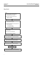
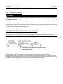
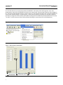
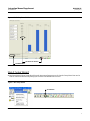
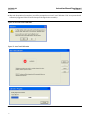
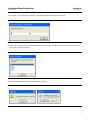
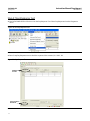
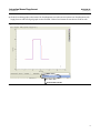
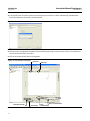
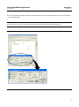
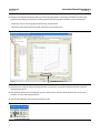
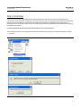
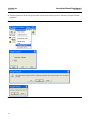
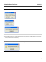
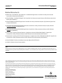
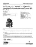
Instruction Manual Supplement
D103285X012
DVC6000 SIS
January 2011
Supplement to FisherR FIELDVUEt DVC6000 SIS
Digital Valve Controllers for Safety Instrumented
System (SIS) Solutions Instruction Manual
Pre‐Commissioning Installation / Setup Guidelines using
ValveLink™ Software
This instruction manual supplement must be used in conjunction with the appropriate Safety Manual for FIELDVUE
DVC6000 SIS Digital Valve Controllers for Safety Instrumented System (SIS) Solutions (0‐20 mA or 0‐24 VDC
[D103035X012] or 4‐20 mA [D103294X012]) and the FIELDVUE DVC6000 SIS Digital Valve Controllers for Safety
Instrumented System (SIS) Solutions Instruction Manual (D103230X012). Page number and figure references are to
the December 2008 version of the instruction manual.
Note
The following procedures are guidelines ONLY, and should be modified/changed according to site specific conditions or
requirements.
Steps 1 through 7 are guidelines for digital valve controllers being installed in the field. In the case where the digital valve
controller is ordered as part of a control valve assembly, the factory mounts the digital valve controller on the actuator, makes
pneumatic connections to the actuator, sets up, and calibrates the instrument; it may only be necessary to run the Setup Wizard
(step 3) to confirm that all setting are correct. Contact your Emerson Process Management sales office if you have any questions
regarding these guidelines.
The pre‐commissioning installation / setup guidelines covered in this supplement can also be accomplished using the 475/375
Field Communicator. Refer to the DVC6000 SIS Digital Valve Controllers for Safety Instrumented System (SIS) Solutions instruction
manual (D103230X012) or the quick start guide (D103307X012) for the Field Communicator menu trees.
www.Fisher.com
Instruction Manual Supplement
DVC6000 SIS
January 2011
D103285X012
Flow Chart
Step 1
Check for proper mounting of the
DVC6000 SIS to the actuator
Check to ensure that sufficient air
supply is available
Step 2
Check for Input Signal, referencing the
DVC6000 SIS nameplate
Apply the appropriate electrical power to
the DVC6000 SIS
• 4‐20 mA for PT‐PT
• 0‐24 VDC for MULTI
Step 3
Run Setup Wizard
Run Auto Travel Calibration
Run Partial Stroke Calibration
Step 4
Perform Step Response Test and save dataset
Step 5
Perform Dynamic Scan and save dataset
Step 6
Perform Partial Stroke Test and save dataset
Step 7
Enable Protection
Proceed with installation and commissioning
2
Instruction Manual Supplement
D103285X012
DVC6000 SIS
January 2011
Step 1: Visual Inspection
WARNING
These guidelines assume that the DVC6000 SIS is properly mounted on the actuator. Improper mounting and installation
could result in personal injury or property damage. Refer to the Installation section of the DVC6000 SIS Instruction Manual
for additional information.
Ensure that the DVC6000 SIS is mounted properly on the actuator with proper tubing to the appropriate ports and that
the air set is properly adjusted and supply pressure is set to the correct values based on the actuator nameplate. Look
for visible indications of broken linkages, brackets, etc.
Step 2: Electrical and Pneumatic Connections
Before connecting electrical power check the DVC6000 SIS nameplate (figure 1) to see if the Input Signal is 4‐20 mA
(Point‐to‐Point) or 0‐24 VDC (Multi‐drop). Provide the appropriate electrical power according to the nameplate.
Figure 1. Typical FIELDVUE DVC6000 SIS Nameplate
E0768
INFORMATION IN THIS AREA INDICATES THE OPERATIONAL MODE SET
AT THE FACTORY. PT‐PT INDICATES POINT‐TO‐POINT LOOP, MULTI
INDICATES MULTI‐DROP LOOP
If the input signal is 4‐20 mA or 0‐20 mA an LC340 line conditioner is NOT required. If the input signal is
0‐24 VDC then an LC340 Line Conditioner is required for HART communications. Alternatively, a HART pass through
multiplexer such as MTL or Pepperl+Fuchs Elcon, may be used, eliminating the need for a line conditioner. Refer to the
DVC6000 SIS Instruction Manual (page 2‐28 through 2‐31: Installation in a 2‐wire system).
Connect pneumatic air supply and ensure sufficient air is supplied to the DVC6000 SIS.
3
Instruction Manual Supplement
DVC6000 SIS
January 2011
D103285X012
Use ValveLink software to communicate with the DVC6000 SIS. Select Status from the Diagnostics menu. Start
monitoring the status of the DVC6000 SIS and check for its control mode. If the operational mode on the nameplate is
PT-PT the control mode should be Analog, as shown in figure 3. If the operational mode on the nameplate is MULTI the
control mode should be Digital, as shown in figure 4. If the control mode does not match the nameplate, follow the
procedure to change the switch position on the PWB according to the DVC6000 SIS Instruction Manual. Refer to page
7-6, table 7‐2 of the instruction manual. When finished checking the control mode click on End Monitoring.
Figure 2. Select Status
Figure 3. Point to Point Control Mode
END MONITORING
4
DIP SWITCH SET TO PT‐PT
Instruction Manual Supplement
DVC6000 SIS
D103285X012
January 2011
Figure 4. Multi‐Drop Control Mode
DIP SWITCH SET TO MULTI
END MONITORING
Step 3: Setup Wizard
Run Setup Wizard. Select Setup Wizard from the Instrument Setup menu or click on the Setup Wizard icon on the
tool bar. ValveLink software will prompt you to set the DVC6000 SIS out of service.
Figure 5. Run Setup Wizard
SETUP WIZARD
5
DVC6000 SIS
January 2011
Instruction Manual Supplement
D103285X012
Figure 6. Set the Instrument Out of Service
After the DVC6000 SIS has been set out of service enter the maximum supply pressure when prompted by ValveLink
software. Click on Next once the value has been entered.
Figure 7. Enter Maximum Supply Pressure
6
Instruction Manual Supplement
D103285X012
DVC6000 SIS
January 2011
Select the Actuator Make, Model, and Size. Check the box if a Volume Booster / Quick Release is being used. Click on
Next when done.
Note
The use of a Quick Exhaust Valve (QEV) with the DVC6000 SIS is not recommended for safety instrumented system applications.
The use of a QEV in an SIS application may cause the valve to cycle or instability during partial stroke test. A Volume Booster is
recommended to improve the stroking speed.
Figure 8. Actuator Information
Enter Valve Mounting Information and the Zero Power Condition (valve position when the DVC6000 SIS has no
signal). Click on Next when done.
Figure 9. Valve Mounting Information
7
DVC6000 SIS
Instruction Manual Supplement
January 2011
D103285X012
Select the Partial Stroke Test Starting Point according to the application. Remove cover to check type of relay used.
Ensure that the correct relay type is selected as this will affect the Partial Stroke Test. Verify that the actual tubing is
the same as the pneumatic hookup represented by ValveLink software. Click on Next when done.
Figure 10. SIS Setup Information
S IF PORT A IS USED FOR PRESSURE
MEASUREMENT OF SOLENOID DURING
TESTING, RELAY B SPECIAL APP SHOULD
BE CHOSEN.
S IF PORT B IS USED FOR PRESSURE
MEASUREMENT OF SOLENOID DURING
TESTING, RELAY C SPECIAL APP SHOULD
BE CHOSEN.
PNEUMATIC HOOKUP
REPRESENTATION
CHECK HERE IF CONNECTED TO LCP100
Select Travel Sensor Motion or let the actuator move to determine the motion. Click on Next when done.
Figure 11. Travel Sensor Motion
8
Instruction Manual Supplement
D103285X012
DVC6000 SIS
January 2011
Select the appropriate Tuning Set. Refer to the Detailed Setup section of the DVC6000 SIS Instruction Manual for
tuning guidelines.
Figure 12. Tuning Set
Select Yes to use Factory Defaults for Setup.
Figure 13. Factory Defaults
9
DVC6000 SIS
January 2011
Instruction Manual Supplement
D103285X012
When the Setup Wizard is complete, you will be prompted to run Auto Travel Calibration. Click Yes to proceed with
calibration (suggested if this is the initial setup of the digital valve controller).
Figure 14. Run Auto Travel Calibration
Figure 15. Auto Travel Calibration
10
Instruction Manual Supplement
D103285X012
DVC6000 SIS
January 2011
Once Auto Travel Calibration is complete, Partial Stroke Calibration will automatically run.
Figure 16. Partial Stroke Calibration
Choose the desired stroke speed for Partial Stroke Calibration, then click OK to finish calibration. Larger actuators
may require a slower test speed.
Figure 17. Choose Desired Test Speed
Put the DVC6000 SIS In Service once calibration is complete.
Figure 18. Put the FIELDVUE DVC6000 SIS In Service When Calibration is Complete
11
DVC6000 SIS
Instruction Manual Supplement
January 2011
D103285X012
Step 4: Step Response Test
Put the DVC6000 SIS Out of Service to run the Step Response Test. Select Step Response from the Diagnostics
menu.
Figure 19. Run Step Response Test
Run a 3 step Step Response test to check the response of the actuator; 0% - 100% - 0%.
Figure 20. Step Response Test
NUMBER
OF STEPS
CLICK TO RUN THE
DIAGNOSTIC
12
Instruction Manual Supplement
DVC6000 SIS
D103285X012
January 2011
Check the resulting graph to determine if the Step Response test results meets requirements. Step Response with
Supply Pressure and Drive Signal graphs are also available. Click on Save Dataset to save the test results to a file.
Figure 21. Step Response Test Results
GRAPH OPTIONS AVAILABLE
13
DVC6000 SIS
Instruction Manual Supplement
January 2011
D103285X012
Step 5: Total Scan
Select Spec Sheet and fill in the information under the Valve, Trim, and Actuator tabs. Click on Save Spec Sheet
when finished.
Figure 22. Spec Sheet
FILL IN THE INFORMATION UNDER THE
VALVE, TRIM, AND ACTUATOR TABS
SAVE SPEC SHEET
Put the DVC6000 SIS Out of Service to run the Dynamic Scan. Select Dynamic Scan > Total Scan from the
Diagnostics menu.
Figure 23. Run Dynamic Scan > Total Scan
14
Instruction Manual Supplement
D103285X012
DVC6000 SIS
January 2011
Click on Run Diagnostic to start the Total Scan.
Figure 24. Total Scan
CLICK TO RUN DIAGNOSTIC
Check the graphs to see if the Valve Signature, Dynamic Error Band, and Drive Signal results are acceptable. Click on
Save Dataset to save the test results to a file.
Figure 25. Total Scan Test Results
15
Instruction Manual Supplement
DVC6000 SIS
January 2011
D103285X012
Step 6: Partial Stroke Test
Select Partial Stroke > Ramp under the Diagnostics menu, as shown below, or
Click on the Partial Stroke Ramp icon on the tool bar.
Note
If there is previous test data present in the microprocessor memory it will be automatically retrieved at this point.
Figure 26. Partial Stroke Test
DIAGNOSTICS
PARTIAL STROKE > RAMP
PARTIAL STROKE RAMP ICON
16
Instruction Manual Supplement
DVC6000 SIS
D103285X012
January 2011
Verify that the test parameters are correct.
Figure 27. Verify Test Parameters
THESE VALUES ARE USED AS AN EXAMPLE
ONLY.
REFER TO PARTIAL STROKE VARIABLE IN THE
DETAILED SETUP SECTION OF THE DVC6000
SIS INSTRUCTION MANUAL (D103230X012)
FOR ADDITIONAL INFORMATION ON VALVE
TEST PARAMETERS
Click on Run Diagnostic, then OK when you are prompted with the Warning screen.
Figure 28. Run Diagnostic
The progress bar will be shown while the Partial Stroke Test is running.
Figure 29. Partial Stroke Test Progress
17
Instruction Manual Supplement
DVC6000 SIS
January 2011
D103285X012
If any Partial Stroke Test data is present in the microprocessor memory, it will be automatically uploaded when
Partial Stroke Ramp is selected in ValveLink software.
Figure 30. Partial Stroke Upload Progress
Once the test is run/uploaded completely, click on the Notes tab to type in the test name. Click on Save Dataset to
the save the Partial Stroke Test results.
Click on the Graph tab and select Valve Signature.
Figure 31. Partial Stroke Test Results
GRAPH TAB
SIGNATURE ANALYZER
18
SAVE DATASET
NOTES TAB
SELECT VALVE SIGNATURE
CLICK
TO ADD OVERLAY
Instruction Manual Supplement
D103285X012
DVC6000 SIS
January 2011
Click on the Signature Analyzer button to analyze friction of the valve. Signature Analyzer serves as a tool to check
on valve performance.
Note
Signature Analyzer is available clicking on the Save Dataset button after completion of the Partial Stroke Test.
Figure 32. Signature Analyzer
19
Instruction Manual Supplement
DVC6000 SIS
January 2011
D103285X012
Clicking on the Add Overlay button allows you to overlay a graph from a previously saved dataset on top of the
graph currently displayed. Overlay the resulting graph with previous graphs and look for any inconsistencies.
Overlay the most recent test graph and look for any inconsistencies.
Overlay the initial (oldest date) test graph and look for any inconsistencies.
Figure 33. Add / Remove Overlay
ADD/REMOVE OVERLAY
Should alarms or alerts be detected during operation, maintenance, or periodic inspection and test, notify the
appropriate personnel.
After the Partial Stroke Test is completed, go to the Status screen and select Start Monitoring to verify that all
variables are in‐line with expected values.
Click the Dataset Report icon and save the report to a file.
Figure 34. Dataset Report
DATASET REPORT ICON
20
Instruction Manual Supplement
D103285X012
DVC6000 SIS
January 2011
Step 7: Protection
If this is the final set up / configuration before the DVC6000 SIS is put into service Protection should be set for
“Configuration and Calibration” to protect for any inadvertent acts as per the appropriate DVC6000 SIS Safety Manual.
When protection is enabled for “Calibration and Configuration” calibration is prohibited and protected setup
parameters cannot be changed. Refer to table 4‐3 of the DVC6000 SIS Instruction Manual for conditions for modifying
DVC6000 SIS parameters.
If company guidelines do not permit protection through use of a jumper skip step 7.
To enable protection, select Change Protection from the Instrument Setup menu. Follow the prompts to enable
protection.
Figure 35. Enable Protection
21
DVC6000 SIS
January 2011
Instruction Manual Supplement
D103285X012
To disable protection, select Change Protection from the Instrument Setup menu. Follow the prompts to disable
protection.
Figure 36. Disable Protection
22
Instruction Manual Supplement
D103285X012
DVC6000 SIS
January 2011
Figure 36. Disable Protection (continued)
Set DVC6000 SIS protection to Configuration & Calibration. Once protection is enabled, the digital valve controller
is ready for installation and commissioning.
Figure 37. Enable Protection for Installation and Commissioning
23
DVC6000 SIS
Instruction Manual Supplement
January 2011
D103285X012
Related Documents
Bulletin 62.1:DVC6000 SIS - Fisher FIELDVUE DVC6000 SIS Digital Valve Controllers for Safety Instrumented
System (SIS) Solutions (D102784X012)
Fisher FIELDVUE DVC6000 SIS Digital Valve Controllers for Safety Instrumented System (SIS) Solutions Instruction
Manual (D103230X012)
Fisher FIELDVUE DVC6000 SIS Digital Valve Controllers for Safety Instrumented System (SIS) Solutions Quick Start
Guide (D103307X012)
Safety Manual for FIELDVUE DVC6000 Digital Valve Controllers for Safety Instrumented System (SIS) Solutions
0‐20 mA or 0‐24 VDC (D103035X012) or
Safety Manual for FIELDVUE DVC6000 Digital Valve Controllers for Safety Instrumented System (SIS) Solutions
4‐20 mA (D103294X012)
Partial Stroke Test Using ValveLink Software—Supplement to Fisher FIELDVUE DVC6000 SIS Digital Valve
Controllers for Safety Instrumented System (SIS) Solutions Instruction Manual (D103274X012)
Partial Stroke Test Using 475/375 Field Communicator—Supplement to Fisher FIELDVUE DVC6000 SIS Digital Valve
Controllers for Safety Instrumented System (SIS) Solutions Instruction Manual (D103320X012)
Fisher FIELDVUE LC340 Line Conditioner Instruction Manual (D102797X012)
ValveLink Software Help or Documentation
Note
Neither Emerson, Emerson Process Management, nor any of their affiliated entities assumes responsible for the selection, use, or
maintenance of any product. Responsibility for the selection, use, and maintenance of any product remains with the purchaser and
end‐user.
Fisher, FIELDVUE, and ValveLink are marks owned by one of the companies in the Emerson Process Management business division of Emerson Electric Co.
Emerson Process Management, Emerson, and the Emerson logo are trademarks and service marks of Emerson Electric Co. All other marks are the property
of their respective owners.
The contents of this publication are presented for informational purposes only, and while every effort has been made to ensure their accuracy, they are not
to be construed as warranties or guarantees, express or implied, regarding the products or services described herein or their use or applicability. All sales are
governed by our terms and conditions, which are available upon request. We reserve the right to modify or improve the designs or specifications of such
products at any time without notice. Neither Emerson, Emerson Process Management, nor any of their affiliated entities assumes responsibility for the
selection, use or maintenance of any product. Responsibility for proper selection, use, and maintenance of any product remains solely with the purchaser
and end user.
Emerson Process Management
Marshalltown, Iowa 50158 USA
Sorocaba, 18087 Brazil
Chatham, Kent ME4 4QZ UK
Dubai, United Arab Emirates
Singapore 128461 Singapore
www.Fisher.com
24
Fisher
Controls International LLC 2007, 2011; All Rights Reserved