1
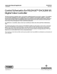
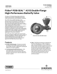
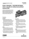
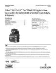
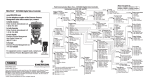
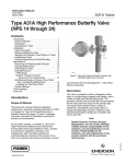
Instruction Manual LCP100 Local Control Panel D103272X012 November 2013 Fisherr LCP100 Local Control Panel Contents Introduction . . . . . . . . . . . . . . . . . . . . . . . . . . . . . . . . . 1 Scope of Manual . . . . . . . . . . . . . . . . . . . . . . . . . . . . . 1 Description . . . . . . . . . . . . . . . . . . . . . . . . . . . . . . . . . 2 Specifications . . . . . . . . . . . . . . . . . . . . . . . . . . . . . . . 2 Installation . . . . . . . . . . . . . . . . . . . . . . . . . . . . . . . . . . 3 Hazardous Area Classifications and Special Instructions for “Safe Use” and Installation in Hazardous Areas . . . . . . . . . . . . . . . . . . . . . . . . 3 Mounting . . . . . . . . . . . . . . . . . . . . . . . . . . . . . . . . . . 5 Electrical Connections . . . . . . . . . . . . . . . . . . . . . . . . 5 Pre‐Setup Testing . . . . . . . . . . . . . . . . . . . . . . . . . . . . 11 Setup . . . . . . . . . . . . . . . . . . . . . . . . . . . . . . . . . . . . . . 12 Principle of Operation . . . . . . . . . . . . . . . . . . . . . . . . 13 Maintenance . . . . . . . . . . . . . . . . . . . . . . . . . . . . . . . . 14 Troubleshooting . . . . . . . . . . . . . . . . . . . . . . . . . . . . 14 Parts Ordering . . . . . . . . . . . . . . . . . . . . . . . . . . . . . . . 14 Parts List . . . . . . . . . . . . . . . . . . . . . . . . . . . . . . . . . . . 15 Common Parts . . . . . . . . . . . . . . . . . . . . . . . . . . . . . 15 Figure 1. Fisher LCP100 Local Control Panel, with FIELDVUE DVC6200 SIS Digital Valve Controller and Bettist Actuator X0247 Introduction Scope of Manual This instruction manual includes installation and maintenance information for the Fisher LCP100 local control panel (figure 1). This device is used with Fisher FIELDVUEt instruments in Safety Instrumented Systems (SIS). Refer to the DVC6200 SIS Digital Valve Controllers for Safety Instrumented System (SIS) Solutions instruction manual (D103557X012) or the DVC6000 SIS Digital Valve Controllers for Safety Instrumented System (SIS) Solutions instruction manual (D103230X012) for additional information. Unless otherwise noted, the information in this instruction manual applies to both DVC6200 SIS and DVC6000 SIS digital valve controllers. For simplicity, the DVC6200 SIS model name will be used throughout. Do not install, operate, or maintain an LCP100 local control panel without being fully trained and qualified in valve, actuator, and accessory installation, operation, and maintenance. To avoid personal injury or property damage, it is important to carefully read, understand, and follow all of the contents of this manual, including all safety cautions and warnings. If you have any questions about these instructions, contact your Emerson Process Management sales office. www.Fisher.com Instruction Manual LCP100 Local Control Panel D103272X012 November 2013 Table 1. Specifications Power Options (switch selectable) J External: 24 VDC +/- 10% @ 50 mA maximum continuous current (100 mA maximum inrush) J Loop: 8‐20 mA (LCP100 and DVC6200 SIS combined) Temperature Limits(1) -40 to 65_C (-40 to 149_F) Maximum distance between LCP100 and DVC6200 SIS digital valve controller Cable length is limited by maximum cable capacitance of 100,000 pF(2). Typical 314 meters (1030 feet) with 18 AWG shielded Audio, Control and Instrumentation Cable. Electromagnetic Interference (EMI) Meets EN 61326-1 (First Edition) Immunity—Industrial locations per Table 2 of EN 61326-1 Standard. Performance is shown in table 2 below. Emissions—Class A ISM equipment rating: Group 1, Class A Connections Conduit: 3/4 NPT or M20 Wiring 14 to 26 AWG Torque Specifications Wiring terminals: 0.5 NSm (4.5 inSlbs) Electrical Classification CSA Ex em IIC T4 Suitable for Zone 1 and Zone 2 locations ATEX Ex e mb [ib] IIC T4 Gb Suitable for Zone 1 and Zone 2 locations Ex ic IIC T4 Gc Suitable for Zone 2 locations IECEx Ex e mb [ib] IIC T4 Gb Suitable for Zone 1 and Zone 2 locations Ex ic IIC T4 Gc Suitable for Zone 2 locations Refer to Hazardous Area Classifications and Special Instructions for “Safe Use” and Installation in Hazardous Locations, starting on page 3, for specific approval information. Electrical Housing IP66 Electrical Installation Wire connections are polarity sensitive Compatibility DVC6200 SIS with Firmware revision 3 or later DVC6000 SIS with Firmware revision 7 or later Installation Orientation Wiring entrance must be pointed down for self‐draining Dimensions 253.1 mm (10 inches) long by 109.5 mm (4.3 inches) wide by 127.8 mm 5 inches) deep. See figure 8. Construction Materials Housing material: filled polyester Approximate Weight 2.2 kg (4.9 lbs) 1. The pressure/temperature limits in this document and any applicable standard or code limitation should not be exceeded. 2. DVC6000 SIS: Cable length is limited by maximum cable capacitance of 18000 pF. Description The LCP100 local control panel is used with the HARTr communicating DVC6200 SIS digital valve controller. This panel is used to manually open and close a safety shutdown valve. The LCP100 also provides a manual reset feature as well as a button for initiating a partial stroke test. Specifications Typical specifications for the LCP100 local control panel are shown in table 1. 2 Instruction Manual LCP100 Local Control Panel D103272X012 November 2013 Table 2. Electromagnetic Immunity Performance Criteria Port Phenomenon Basic Standard Electrostatic discharge (ESD) IEC 61000‐4‐2 Radiated EM field IEC 61000‐4‐3 Enclosure Test Level $4 kV contact $8 kV air 80 to 1000 MHz @ 10V/m with 1 kHz AM at 80% 1400 to 2000 MHz @ 3V/m with 1 kHz AM at 80% Performance Criteria(1) A A 2000 to 2700 MHz @ 1V/m with 1 kHz AM at 80% I/O signal/control Burst (fast transients) IEC 61000‐4‐4 Surge IEC 61000‐4‐5 Conducted RF IEC 61000‐4‐6 $1 kV, I/O lines $2 kV, DC power lines $1 kV, I/O lines $2 kV, DC power lines) 150 kHz to 80 MHz at 3 Vrms with 1 kHz AM at 80% A A A Specification limit = ±1% of span 1. A = No degradation during testing. B = Temporary degradation during testing, but is self‐recovering. Installation WARNING Electrostatic charge hazard. Do not rub or clean the LCP100 with solvents if a flammable vapor is present. To do so could result in an explosion. Note Inside the LCP100 compartment, direct all wiring to the left side; away from the buttons. Hazardous Area Classifications and Special Instructions for “Safe Use” and Installation in Hazardous Locations Certain nameplates may carry more than one approval, and each approval may have unique installation/wiring requirements and/or conditions of “safe use”. These special instructions for “safe use” are in addition to, and may override, the standard installation procedures. Special instructions are listed by approval. WARNING Failure to follow these conditions of “safe use” could result in personal injury or property damage from fire or explosion, and area re‐classification. Note This information supplements the nameplate markings affixed to the product. Always refer to the nameplate itself to identify the appropriate certification. If the LCP100 is connected to a DVC6200 SIS in a zone 1 explosion proof “d” environment, there must be a conduit seal installed between the DVC6200 SIS and the LCP100 in order to maintain the explosion proof integrity of the DVC6200 SIS. Refer to figures 11 and 12. 3 Instruction Manual LCP100 Local Control Panel D103272X012 November 2013 The LCP100 can be connected to a DVC6200 SIS that is part of an intrinsically safe system provided that you follow the instructions for the LCP100 Ex ic installation, as shown in figures 4 and 7. The overall intrinsically safe system would be rated as an Ex ic system. For all other approvals use zone 1 approved wiring practices. CSA Ex em IIC, IP66 Rated 30 VDC maximum; 100 mA maximum; temperature code rating T4, ambient temperature range -40_C to 65_C Special Conditions of Use 1. Install in an area that has a low risk of mechanical damage. 2. Install the cover, tightening the screws evenly in a criss‐cross pattern such as the one indicated in figure 2 to help ensure the cover is properly installed. Figure 2. Proper Cover Installation 3 2 1 4 NOTE: TIGHTEN THE SCREWS IN A CRISS‐CROSS PATTERN TO HELP ENSURE PROPER COVER INSTALLATION ATEX / IECEx ATEX: II 2G Ex e mb [ib] IIC T4 Gb ATEX: II 3G Ex ic IIC T4 Gc IECEX: Ex e mb [ib] IIC T4 Gb ATEX: Ex ic IIC T4 Gc Ta = -40_C to +65_C IP66 Entity parameters for intrinsically safe applications: Ui = 27 VDC, Ci = 1.1 nF, and Li = 0 Standards Used for Certification IEC 60079-0:2004 IEC 60079-0:2007 IEC 60079-7:2006 4 IEC 60079-11:2006 IEC 60079-18:2004 EN 60079-0:2006 EN 60079-7:2007 EN 60079-11:2007 EN 60079-18:2004 Instruction Manual D103272X012 LCP100 Local Control Panel November 2013 Special Conditions for Safe Use 1. For Ex ic installations, it is not permitted to connect separate supplies to the LOOP+/LOOP and AUX+/LOOP terminals. 2. If the equipment is installed in a zone 2, the installer shall take suitable steps to indicate whether the equipment is installed as Ex e mb [ib] or Ex ic. Mounting Refer to figure 8 for dimensional information. The LCP100 local control panel has four (4) mounting holes for on‐site mounting of the device. The LCP100 must be installed so that the wiring connections are on the bottom to prevent accumulation of moisture inside the box. Electrical Connections WARNING Select wiring and/or cable glands that are rated for the environment of use (such as hazardous location, ingress protection, and temperature). Failure to use properly rated wiring and/or cable glands can result in personal injury or property damage from fire or explosion. Wiring connections must be in accordance with local, regional, and national codes for any given hazardous area approval. Failure to follow the local, regional, and national codes could result in personal injury or property damage from fire or explosion. Electrical connections for explosion-proof applications are shown in figures 3, 5, and 6. Electrical connections for intrinsically safe applications are shown in figures 4 and 7. Note For intrinsically safe applications, the LCP100 forms an intrinsically safe explosion protection system when used with intrinsically safe associated apparatus (a barrier) or with any other intrinsically safe devices. The following requirements must be met: Uo ≤ Ui , Io ≤ Ii, Po ≤ Pi , Co ≥ Ci + Cc, Lo ≥ Li + Lc. There are two methods to power the LCP100. Method one requires an external 24 VDC source to power the LCP100. Method two uses loop power wiring in series. In method one, shown in figure 3 or 4, signal wiring is brought to the enclosure through a 3/4 NPT or M20 housing conduit connection (connection type is identified on nameplate). Method two can be accomplished in two ways; with the wiring going first to the LCP100, then to the DVC6200 SIS, as shown in in figure 5, or with the wiring going first to the DVC6200 SIS, then to the LCP100, as shown in figure 6 or 7. However, because the LCP100 does consume energy to drive the pushbuttons and lights, the minimum current signal from the logic solver must be 8 mA. If the logic solver cannot provide an output range of 8‐20 mA, then method one must be used. 5 Instruction Manual LCP100 Local Control Panel D103272X012 November 2013 When connections are complete move the DIP switch to the appropriate power setting. If external 24 VDC is used to power the LCP100, make sure the switch is on the side that says “24VDC”. If loop power is used, slide the switch to the side that says “LOOP”. Note Factory default for the DIP switch power selector is 24VDC. When installing the cover, tighten the screws evenly in a criss‐cross pattern such as the one indicated in figure 2 to help ensure the cover is properly installed. Figure 3. Wiring for 24 VDC External Power Configuration; Explosion-proof Applications 24VDC LOGIC SOLVER OUTPUT 4‐20 mA (USER SUPPLIED) SWITCH TO 24VDC POSITION LCP100 AUX + 24VDC + CASE GROUND 24 VDC SOURCE 24VDC * AUX* 1 (USER SUPPLIED) DVC6200 SIS TERMINAL BOX SHIELD NOT CONNECTED TO LCP100 SIMPLE METHOD FOR INSTALLING AN LCP100 TO AN EXISTING DVC6200 SIS INSTRUMENT WHEN 24 VDC POWER IS AVAILABLE NOTE: DO NOT CONNECT THE LOOP + TERMINAL IN THE LCP100 TO THE LOOP + TERMINAL IN THE DVC6200 SIS. THIS WILL CAUSE THE LCP100 TO UNNECESSARILY CONSUME 4 mA AT THE EXPENSE OF THE DVC6200 SIS. 1 THIS CONNECTION IS ALSO LABELED LOOP -. E1465 6 Instruction Manual LCP100 Local Control Panel D103272X012 November 2013 Figure 4. Wiring for 24 VDC External Power Configuration; Intrinsically Safe Applications LOGIC SOLVER OUTPUT 4‐20 mA 24VDC INTRINSICALLY SAFE BARRIER (USER SUPPLIED) SWITCH TO 24VDC POSITION LCP100 AUX + 24VDC + 24 VDC SOURCE CASE GROUND 24VDC * 1 AUX* (USER SUPPLIED) DVC6200 SIS TERMINAL BOX SHIELD NOT CONNECTED TO LCP100 INTRINSICALLY SAFE BARRIER SIMPLE METHOD FOR INSTALLING AN LCP100 TO AN EXISTING DVC6200 SIS INSTRUMENT WHEN 24 VDC POWER IS AVAILABLE NON-HAZARDOUS LOCATION HAZARDOUS LOCATION NOTE: DO NOT CONNECT THE LOOP + TERMINAL IN THE LCP100 TO THE LOOP + TERMINAL IN THE DVC6200 SIS. THIS WILL CAUSE THE LCP100 TO UNNECESSARILY CONSUME 4 mA AT THE EXPENSE OF THE DVC6200 SIS. 1 THIS CONNECTION IS ALSO LABELED LOOP -. 7 Instruction Manual LCP100 Local Control Panel D103272X012 November 2013 Figure 5. Wiring for Loop‐Powered Configuration; Logic Solver Wired to the Fisher LCP100 then the FIELDVUE DVC6200 SIS ; Explosion-proof Applications LCP100 LOOP SWITCH TO LOOP POSITION AUX + LOGIC SOLVER OUTPUT 1 LOOP + 8‐20 mA CASE GROUND LOOP * (USER SUPPLIED) DVC6200 SIS TERMINAL BOX THE DVC6200 SIS MUST BE IN POINT‐TO‐POINT MODE SHIELD NOT CONNECTED TO LCP100 NOTE: 1 THE LOGIC SOLVER MINIMUM OUTPUT MUST BE AT LEAST 8 mA. THE LCP100, WHEN POWERED BY THE LOOP, CONSUMES APPROXIMATELY 4 mA. E1466 POINT‐TO‐POINT MODE LCP100 LOOP SWITCH TO LOOP POSITION AUX + LOGIC SOLVER OUTPUT 1 LOOP + 24VDC CASE GROUND LOOP * (USER SUPPLIED) DVC6200 SIS TERMINAL BOX THE DVC6200 SIS MUST BE IN MULTI‐DROP MODE SYS - /) LC340 LINE CONDITIONER FLD - /) SHIELD NOT CONNECTED TO LCP100 NOTE: 1 THE LCP100, WHEN POWERED BY THE LOOP, CONSUMES APPROXIMATELY 4 mA. E1467 8 MULTI‐DROP MODE Instruction Manual LCP100 Local Control Panel D103272X012 November 2013 Figure 6. Wiring for Loop‐Powered Configuration; Logic Solver Wired to the FIELDVUE DVC60200 SIS then the Fisher LCP100; Explosion-proof Applications LCP100 SWITCH TO LOOP POSITION LOOP AUX + CASE GROUND LOGIC SOLVER OUTPUT 1 LOOP + 8‐20 mA LOOP * (USER SUPPLIED) DVC6200 SIS TERMINAL BOX THE DVC6200 SIS MUST BE IN POINT‐TO‐POINT MODE SHIELD NOT CONNECTED TO LCP100 NOTE: 1 THE LOGIC SOLVER MINIMUM OUTPUT MUST BE AT LEAST 8 mA. THE LCP100, WHEN POWERED BY THE LOOP, CONSUMES APPROXIMATELY 4 mA. E1468 POINT‐TO‐POINT MODE LCP100 LOOP SWITCH TO LOOP POSITION AUX ) CASE GROUND LOGIC SOLVER OUTPUT 1 LOOP ) 24VDC FLD - /) ) (USER SUPPLIED)* SYS - /) LOOP * LC340 LINE CONDITIONER DVC6200 SIS TERMINAL BOX THE DVC6200 SIS MUST BE IN MULTI‐DROP MODE SHIELD NOT CONNECTED TO LCP100 NOTE: 1 THE LCP100, WHEN POWERED BY THE LOOP, CONSUMES APPROXIMATELY 4 mA. E1469 MULTI‐DROP MODE 9 Instruction Manual LCP100 Local Control Panel D103272X012 November 2013 Figure 7. Wiring for Loop‐Powered Configuration; Logic Solver Wired to the FIELDVUE DVC60200 SIS then the Fisher LCP100; Intrinsically Safe Applications LOOP LCP100 SWITCH TO LOOP POSITION AUX + CASE GROUND LOGIC SOLVER OUTPUT 1 8‐20 mA LOOP + INTRINSICALLY SAFE BARRIER LOOP* (USER SUPPLIED) DVC6200 SIS TERMINAL BOX THE DVC6200 SIS MUST BE IN POINT‐TO‐POINT MODE SHIELD NOT CONNECTED TO LCP100 NON-HAZARDOUS LOCATION NOTE: 1 THE LOGIC SOLVER MINIMUM OUTPUT MUST BE AT LEAST 8 mA. THE LCP100, WHEN POWERED BY THE LOOP, CONSUMES APPROXIMATELY 4 mA. 10 HAZARDOUS LOCATION POINT‐TO‐POINT MODE Instruction Manual LCP100 Local Control Panel D103272X012 November 2013 Figure 8. Fisher LCP100 Local Control Panel Dimensions 194 (7.6) 129 (5.1) E1077‐1 257 (10.1) 94 (3.7) 110 (4.3) mm (INCH) Pre‐Setup Testing Before connecting the LCP100 to the process, conduct the following tests on the LCP100 connected to the DVC6200 SIS. Successful Partial Stroke Test 1. Press the Valve Test (bottom) pushbutton for more than 3 seconds (but less than 10 seconds). 2. Observe that the green light starts flashing when the valve starts moving. 3. Observe that the valve moves no more than the configured partial stroke test travel limit. 4. Observe that the valve returns to the normal operating position and the green light comes on solid. Manually Aborted Partial Stroke Test 1. Press the Valve Test (bottom) pushbutton for more than 3 seconds (but less than 10 seconds). 2. Observe that the green light starts flashing when the valve starts moving. 3. Before the valve reaches the travel limit of the configured partial stroke test, press the Valve Test pushbutton, or the pushbutton next to the green light. 4. Observe that the valve immediately returns to the normal operating position and the green light comes on solid. 11 LCP100 Local Control Panel Instruction Manual November 2013 D103272X012 Emergency Demand through the Logic Solver 1. Reduce the current to the DVC6200 SIS to 4 mA (for de‐energize to trip operation). Note For a loop powered installation, a minimum current of 8 mA is required at the trip state / “Safety Demand” for proper functioning of the pushbuttons and lights. 2. Observe that the valve moves to its fail safe state. 3. Observe that the red light comes on solid and the yellow light stays off. 4. Press the pushbutton next to the green light and observe that the valve does not move. 5. Increase the current to the DVC6200 SIS to 20 mA (for de‐energize to trip) and observe that the valve remains in its fail safe state. 6. Observe that the red light stays on solid and the yellow light comes on solid (ready to reset). 7. Press the pushbutton next to the green light. 8. Observe that the red light goes off, the valve moves to its normal operating position, and then the green light comes on solid. Emergency Demand through Local Control Panel 1. Press the pushbutton next to the red light. 2. Observe that the valve moves to it fail safe position. 3. Observe that the red light comes on solid and the yellow light comes on solid (ready to reset). 4. Press the pushbutton next to the green light. 5. Observe that the red light goes off, the valve moves to its normal operating position, and then the green light comes on solid. Setup In order for the LCP100 to operate properly, it must be connected to a DVC6200 SIS with firmware revision 3 or later, or a DVC6000 SIS device with firmware revision 7 or later. Once the physical connections are made, use the following checklist to configure the LCP100. Refer to the DVC6200 SIS instruction manual (D103557X012) or the DVC6000 SIS instruction manual (D103230X012) if additional setup information is needed. D Using a 475 Field Communicator select Configure > Guided Setup > Device Setup. Follow the prompts on the Field Communicator: Enter Supply Pressure and Unit Enter Actuator Make, Model, and Size Enter Partial Stroke test Starting Point, Relay Type and Zero Power Condition [select the “instrument connected to local control panel (LCP100)” option] 12 Instruction Manual LCP100 Local Control Panel D103272X012 November 2013 D Follow the prompts to complete Device Setup. The following parameters will be automatically set under Travel Alerts: d Hi Hi / Lo Lo Enable - Yes d Lo Lo Point (%) - 1 d Hi Hi Point (%) - 99 d Deadband (%) - 0.5 d DVC Power Up - Manual Reset D Continue to set up the digital valve controller according the normal set up procedure. D Remember to place the instrument back in service before disconnecting. Note An alternative method to configure the LCP100 is through Detailed Setup. Using the Field Communicator, select Configure > Manual Setup > Instrument > Terminal Box > Edit Auxiliary Terminal Action > SIS Local Control Panel. When this setting is downloaded to the device, an information screen will pop up advising that some additional parameters will be configured. Select Yes. Principle of Operation The lights indicate the state of the valve as described in table 3. Table 3. Fisher LCP100 Light and Button Operation WHAT THE LCP100 LIGHTS SHOW... POSSIBLE CONDITIONS... PRESS INDICATED BUTTON TO... Top Middle Bottom --- Trip Run PST Trip Stop PST Trip Run PST --- --- Trip Run PST Trip Run PST --- --- --- Solid The valve is in its normal operating state. Fast Blink (1/2 second) The valve is in the process of running a partial stroke Stop PST test (PST). The valve is not at its normal operating position because Acknowledge the actuator pressure is low or the valve is stuck. PST Failure The valve is tripped but is stuck at the normal position. --Acknowledge PST Failure Acknowledge PST Failure Slow Blink (1 second) A partial stroke test has failed. Solid The valve is tripped due to loss of actuator pressure (e.g., solenoid valve trip) The valve is tripped due to a command from the logic solver or LCP100. The valve is stuck in the tripped state. --- --- --- Fast Blink (1/2 second) The valve is at mid-travel after a trip. The valve may be moving or stuck in this position. --- --- --- Solid The valve may be reset to the normal operating state. Reset to Normal State --- --- NOTES 1. If the green, red, and yellow lights are blinking in sequence, then the DVC6200 SIS is out of service. In point-to-point mode, the DVC6200 SIS will not respond to a trip from the logic solver. 2. Depending on the emergency shutdown valve configuration, the top button could be labeled “Valve Open” and the middle button could be labeled “Valve Close”; or vice versa. The bottom button will aways be labeled “Valve Test”. 3. Acknowledgment of a PST failure means that the LCP100 will return the blinking green light to solid green. The PST alert will still be visible via HART communication with the DVC6200 SIS. 4. If the red and green lights are both solid the valve is throttling in mid‐travel. 5. The information contained in this table applies to firmware 9 and later. 13 Instruction Manual LCP100 Local Control Panel D103272X012 November 2013 Note The primary safety function should be implemented by controlling the current (in point‐to‐point mode) or voltage (in multi‐drop mode) from the logic solver. The red button is not intended to perform the primary safety function for the process. Maintenance WARNING Electrostatic charge hazard. Do not rub or clean the LCP100 with solvents if a flammable vapor is present. To do so could result in an explosion. The LCP100 has four major components; the housing, lights, conduit connections, and electronics. If a light is not working it can be replaced with the appropriate color. The conduit connections do not normally need replacement. The electronics module can be replaced as an assembly without having to disconnect the conduit connections or remove the box from its mounting. Instrument Troubleshooting If difficulties are experienced with the LCP100 control panel, refer to table 4. Table 4. Instrument Troubleshooting Symptom Possible Cause 1. Lights are not lit. 1. LCP100 is not properly connected to the digital valve controller aux. terminal. 2. LCP100 is properly connected to the digital valve controller aux. terminal, but the lights are not lit. 2. Power switch is not set correctly. Action 1. Ensure that the LCP100 is connected correctly to the digital valve controller aux. terminal, as described in the Installation section of this manual. 2. Ensure that the power switch is set correctly. If Loop Power is used, ensure that the switch position is set to Loop Power, and NOT 24 VDC, and vice versa. 3. The power switch is set 3. Loop Power option is selected, but there is not enough correctly, but the lights are current. not lit. 4. The LCP100 and the digital 4. The LED may be damaged. valve controller are properly connected, and there is sufficient current but the lights are not lit. 3. The Loop Power Option requires 8 mA current to operate. Ensure that there is sufficient current. 5. Lights are blinking. 5. Valve is not at it's normal stop. 5. Check for proper calibration. Re‐run calibration if necessary. 6. Proper calibration but lights are blinking. 6. Hi Hi / Lo Lo alerts settings not correctly set. 6. Ensure that the Hi Hi / Lo Lo Alert settings are 99 and 1% respectively. For large rotary valve, adjust settings to 98 and 2% and observe. 4. Replace LED. Parts Ordering When corresponding with your Emerson Process Management sales office about this equipment, mention the serial number found on the nameplate (key 10, figure 9) of the unit. When ordering replacement parts, state the complete 11‐character part number of each part required as found in the following parts list. 14 Instruction Manual LCP100 Local Control Panel D103272X012 November 2013 WARNING Use only genuine Fisher replacement parts. Components that are not supplied by Emerson Process Management should not, under any circumstances, be used in any Fisher instrument. Use of components not supplied by Emerson Process Management may void your warranty and hazardous area approval, might adversely affect the performance of the instrument, and could cause personal injury and property damage. Parts Kits Description LED Assemblies Kit Includes LED's (qty. 3); Yellow, Red, and Green (keys 11*, 12*, and 13*, see figure 9) and fasteners (qty. 6) (key 8, see figure 9) Enclosure Labels Kit Includes labels (qty. 6); OPEN, CLOSED, VALVE OPEN, VALVE CLOSE, READY TO RESET, and VALVE TEST Parts List Part Number Common Parts (see figures 9 and 10) GE25751X012 GE25750X012 Key Description 3 3/4 NPT Conduit (2 req'd) M20 Conduit (2 req'd) Machine Screw (4 req'd) Electronics Module (see figure 10) 5 9 Part Number GE24442X012 GE34487X012 GE22073X012 GE39919X012 Figure 9. Fisher LCP100 Assembly GE37243‐B E1121 *Recommended spare parts Only available in the LED Assemblies Parts Kit 15 LCP100 Local Control Panel November 2013 Figure 10. Key 9, Electronics Module GE39919‐A E1122 16 Instruction Manual D103272X012 Instruction Manual LCP100 Local Control Panel D103272X012 November 2013 Figure 11. Fisher LCP100 Connection to Explosion Proof “Ex d” FIELDVUE DVC6200 SIS; Loop Power ZONE 1 NON‐HAZARDOUS AREA CONDUIT SEAL LOGIC SOLVER DVC6200 SIS “Ex d” LCP100 “Ex em” LOOP POWERED—LOGIC SOLVER WIRED TO LCP100 FIRST ZONE 1 OR 2 NON‐HAZARDOUS AREA CONDUIT SEAL DVC6200 SIS “Ex d” LOGIC SOLVER CONDUIT SEAL LCP100 “Ex em” E1080-2 LOOP POWERED—LOGIC SOLVER WIRED TO DVC6200 SIS FIRST 17 Instruction Manual LCP100 Local Control Panel D103272X012 November 2013 Figure 12. Fisher LCP100 Connection to Explosion Proof “Ex d” FIELDVUE DVC6200 SIS; 24 VDC Power ZONE 1 OR 2 NON‐HAZARDOUS AREA CONDUIT SEAL DVC6200 SIS “Ex d” LOGIC SOLVER CONDUIT SEAL 24V SUPPLY LCP100 “Ex em” E1081-2 18 Instruction Manual D103272X012 LCP100 Local Control Panel November 2013 19 LCP100 Local Control Panel November 2013 Instruction Manual D103272X012 Neither Emerson, Emerson Process Management, nor any of their affiliated entities assumes responsibility for the selection, use or maintenance of any product. Responsibility for proper selection, use, and maintenance of any product remains solely with the purchaser and end user. Fisher, FIELDVUE, and Bettis are marks owned by one of the companies in the Emerson Process Management business unit of Emerson Electric Co. Emerson Process Management, Emerson, and the Emerson logo are trademarks and service marks of Emerson Electric Co. HART is a mark owned by the HART Communication Foundation. All other marks are the property of their respective owners. The contents of this publication are presented for informational purposes only, and while every effort has been made to ensure their accuracy, they are not to be construed as warranties or guarantees, express or implied, regarding the products or services described herein or their use or applicability. All sales are governed by our terms and conditions, which are available upon request. We reserve the right to modify or improve the designs or specifications of such products at any time without notice. Emerson Process Management Marshalltown, Iowa 50158 USA Sorocaba, 18087 Brazil Chatham, Kent ME4 4QZ UK Dubai, United Arab Emirates Singapore 128461 Singapore www.Fisher.com 20 E 2007, 2013 Fisher Controls International LLC. All rights reserved.