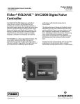
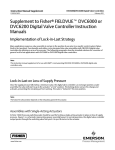
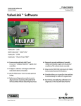
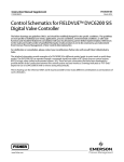
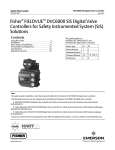
1
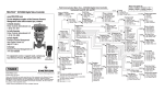
Product Bulletin DVC6200 SIS Digital Valve Controller 62.1:DVC6200 SIS September 2013 D103555X012 Fisherr FIELDVUEt DVC6200 SIS Digital Valve Controller for Safety Instrumented Systems (SIS) The FIELDVUE DVC6200 SIS digital valve controller is a HARTr communicating instrument for use in valve applications such as Emergency Shutdown, Emergency Blow Down, Emergency Venting, and Emergency Isolation. The DVC6200 SIS is capable of monitoring the health of and controlling the safety shutdown function of a valve and can easily be installed on most Fisher and non‐Fisher pneumatic actuators. Features Reliability n Linkage‐less Position Feedback—The high performance, linkage‐less feedback system eliminates physical contact between the valve stem and the DVC6200 SIS. This minimizes the affects of pipeline vibration and environmental corrosion. n Built to Survive—The field proven DVC6200 SIS instrument has fully encapsulated electronics that resist the effects of vibration, temperature, and corrosive atmospheres. A weather‐tight wiring terminal box isolates field wiring connections from other areas of the instrument. Safety n Partial Stroke Testing (PST)—This is a small ramp test that moves the valve, without disrupting the process, to detect a stuck valve. Testing can be automated, or manually initiated with an external pushbutton or Fisher LCP100 Local Control Panel. n Full Stroke Testing (FST)—This is a full ramp over the entire valve travel range that is typically performed during a shut down. This test can reveal failures undetected by the PST on-line diagnostic testing. www.Fisher.com X0079 Ease of Use n Remote Access—The DVC6200 SIS is a HART communicating device, so information can be accessed anywhere along the loop. This flexibility can reduce exposure to hazardous environments and make it easier to evaluate valves in hard to reach locations. n Faster Commissioning—HART communication allows you to quickly commission loops with a variety of tools, either locally at the valve assembly or remotely. n Easy Maintenance—The DVC6200 SIS digital valve controller is modular in design. Critical working components can be replaced without removing field wiring or pneumatic tubing. Value n Spurious Trip Protection—PST Pressure Limit defines the output pressure threshold that will abort the partial stroke test if exceeded. This prevents the actuator from completely exhausting pressure and potentially causing a spurious trip in a sticking valve scenario. Product Bulletin DVC6200 SIS Digital Valve Controller 62.1:DVC6200 SIS September 2013 n Increased Uptime—The self‐diagnostic capability of the DVC6200 SIS provides valve availability and health evaluation without shutting down the process or pulling the valve assembly from the line. n Audit Documentation—Using ValveLink™ software, a time and date stamp on all tests and reports provides compliance with requirements of statutory authorities. D103555X012 Packaged Solutions LCP100—A local control panel can be connected directly to the DVC6200 SIS to provide manual control of the SIS valve, including manual reset. A partial stroke test can also be initiated with the LCP100 (see figure 1). Figure 1. Fisher LCP100 Local Control Panel n Hardware Savings—When installed in an integrated control system, significant hardware and installation cost savings can be achieved. Valve accessories such as limit switches and position transmitters can be eliminated because this information is available via the HART communication protocol. In addition, an integrated 4‐20 mA position transmitter or limit switch option is available. n Improved Maintenance Decisions—Digital communication provides easy access to the condition of the valve. Sound process and asset management decisions can be made by analysis of valve diagnostic information through ValveLink software, DD's, or DTM's. X0248 Safety Certification The functional safety assessment was performed to the requirements of IEC 61508: ed2, 2010, SIL3. The DVC6200 SIS digital valve controller, in the de-energize to trip (DETT) or energize to trip (ETT) configuration, meets the systematic integrity requirements of SIL 3. The DVC6200 SIS position monitor, in the position transmitter or limit switch configuration, meets the systematic integrity requirements of SIL 2. 2 Figure 2. exida Certificates Product Bulletin DVC6200 SIS Digital Valve Controller 62.1:DVC6200 SIS September 2013 D103555X012 Valve Diagnostics The DVC6200 SIS digital valve controller provides a broad and deep portfolio of valve diagnostic capabilities. Whether the 475 Field Communicator is used to check for valve alerts and operational status, or ValveLink software is used for comprehensive diagnostic test and analysis, the tools are easy to use. Valve diagnostic tests enable condition and performance monitoring of the entire valve assembly not just the digital valve controller. Results are displayed graphically, with severity indicated by a red/yellow/green icon. A detailed description of the identified issue as well as suggestions for recommended actions are provided. In the event that the DVC6200 SIS is commanded to trip, diagnostic data can be gathered automatically to be used for troubleshooting. Solenoid Valve Health Monitoring If a solenoid valve is installed between the DVC6200 SIS pressure output and the actuator, as shown in figure 3, the final control element assembly can be configured to verify the operation of the solenoid valve during online operation. In single-acting actuator applications, the “unused” output port of the DVC6200 SIS can be piped such that the pressure downstream of the of solenoid valve is measured. When the solenoid valve is pulsed, the DVC6200 SIS can sense the momentary pressure drop across the solenoid valve. The solenoid should be pulsed long enough to detect a pressure drop across the solenoid valve, but not so long that it affects the travel of the final control element. This not only increases the availability of the solenoid valve during a safety demand, but also enhances the reliability of the SIF (Safety Instrumented Function) loop. Figure 3. Solenoid Valve Testing S Examples of identifiable issues are: AS n Valve Stuck n Solenoid Stuck n Low air supply or pressure droop n Dirty air supply E1460 n External air leak (actuator diaphragm or tubing) TRAVEL SET POINT n Piston actuator O‐ring failure TRAVEL n Excessive valve assembly friction n Low valve assembly friction PORT B PRESSURE n Broken actuator spring 0.095 sec n Broken valve/actuator shaft For additional information on FIELDVUE diagnostics and ValveLink software refer to Bulletin 62.1:ValveLink Software (D102227X012). 0.100 sec E1028 ValveLink Software Screen Image Showing Pressure Drop Across the Solenoid Valve 3 Product Bulletin DVC6200 SIS Digital Valve Controller 62.1:DVC6200 SIS September 2013 D103555X012 Application Examples Figure 4. De-Energize to Trip (DETT) FIELDVUE DVC6200 SIS and DETT Solenoid Valve LOGIC SOLVER OR DCS LOGIC SOLVER 4-20 mA DETT OR 0-24 VDC DETT LOGIC SOLVER 0-24 VDC DETT 0-24 VDC DETT 1 2 FISHER LC340 2 LINE CONDITIONER LOW POWER SOLENOID VALVE S S AS E1455 AS E1456 Options Available n LCP100 Local Control Panel or external pushbutton n Integral 4-20 mA position transmitter or discrete switch Benefits n DVC6200 SIS provides diagnostic coverage with PST n DVC6200 SIS used with solenoid can provide redundant safety function n DVC6200 SIS can provide additional diagnostic coverage when optional solenoid pulse recording is utilized n When powered by 4-20 mA, the DVC6200 SIS is capable of recording the demand and reset stroke Operation n DVC6200 SIS will move to the safety demand state upon signal deenergization, loss of power, or loss of pneumatic supply 1 2 4 An LC340 line conditioner is required for 0-24 VDC DETT LC340 mounting requires standard 35 mm DIN rail; install in marshalling or I/O cabinet, or junction box. For additional information refer to the LC340 instruction manual (D102797X012), available at www.FIELDVUE.com or from your Emerson Process Management sales office. Product Bulletin DVC6200 SIS Digital Valve Controller 62.1:DVC6200 SIS September 2013 D103555X012 Figure 5. De-Energize to Trip (DETT) FIELDVUE DVC6200 SIS; No Solenoid Valve LOGIC SOLVER LOGIC SOLVER 0-24 VDC DETT 4-20 mA DETT 1 LC340 LINE CONDITIONER AS AS E1457 E1458 Options Available n LCP100 Local Control Panel or external pushbutton n Integral 4-20 mA position transmitter or discrete switch Benefits n DVC6200 SIS provides diagnostic coverage with PST n Eliminates solenoid valve n When powered by 4-20 mA, the DVC6200 SIS is capable of recording the demand and reset stroke Operation n DVC6200 SIS will move to the safety demand state upon signal deenergization, loss of power, or loss of pneumatic supply 1 LC340 mounting requires standard 35 mm DIN rail; install in marshalling or I/O cabinet, or junction box. For additional information refer to the LC340 instruction manual (D102797X012), available at www.FIELDVUE.com or from your Emerson Process Management sales office. 5 Product Bulletin DVC6200 SIS Digital Valve Controller 62.1:DVC6200 SIS September 2013 D103555X012 Figure 6. FIELDVUE DVC6200 SIS for PST only and DETT Solenoid Valve LOGIC SOLVER OR DCS LOGIC SOLVER 4-20 mA ETT 0-24 VDC DETT S AS SINGLE-ACTING, REVERSE (RELAY B) 4 mA = FULL SUPPLY TO ACTUATOR E1459 Options Available n LCP100 Local Control Panel or external pushbutton n Integral 4-20 mA position transmitter or discrete switch Benefits n The energize to trip option provides maximum actuator pressure at minimum control signal (4 mA). Therefore, loss of the control signal will not cause the valve to trip. n Prevents spurious trip on loss of electrical power to DVC6200 SIS n DVC6200 SIS can provide additional diagnostics coverage when performing PST n DVC6200 SIS can provide additional diagnostic coverage when optional solenoid pulse recording is utilized Operation n DVC6200 SIS will move to the safety demand state upon signal energization or loss of pneumatic supply n The solenoid valve will move to the safety demand state upon signal de-energization 6 Product Bulletin DVC6200 SIS Digital Valve Controller 62.1:DVC6200 SIS September 2013 D103555X012 Specifications Maximum Span: 9.5 bar (140 psig) Action: Double, Single Direct, or Single Reverse Available Mounting J Sliding‐stem linear applications J Quarter‐turn rotary applications J Integral mounting to Fisher rotary actuators J Integral mounting to the Fisher GX control valve and Electronic Output(2) J Integral 4‐20 mA Position Transmitter: 4‐20 mA output, isolated Supply Voltage: 8‐30 VDC Fault Indication: offrange high or low Reference Accuracy: 1% of travel span Safety Accuracy: 5% of travel span J Integral Limit Switch: One isolated switch, configurable throughout the calibrated travel range or actuated from a device alert Off State: 0 mA (nominal) On State: up to 1 A Supply Voltage: 30 VDC maximum Reference Accuracy: 2% of travel span Safety Accuracy: 5% of travel span actuator system DVC6200 SIS digital valve controllers can also be mounted on other actuators that comply with IEC 60534‐6‐1, IEC 60534‐6‐2, VDI/VDE‐3845, and NAMUR mounting standards Communication Protocol J HART 5 or J HART 7 Input Signal Point‐to‐Point Analog Input Signal: 4‐20 mA DC, nominal Steady State Air Consumption(3)(4) Minimum Voltage Available at Instrument Terminals must be 9.5 VDC for analog control, 10 VDC for HART communication Minimum Control Current: 4.0 mA Minimum Current w/o Microprocessor Restart: 3.5 mA Maximum Voltage: 30 VDC Overcurrent protected Reverse Polarity protected Low Bleed Relay At 1.4 bar (20 psig) supply pressure: 0.056 normal m3/hr (2.1 scfh), average At 5.5 bar (80 psig) supply pressure: 0.184 normal m3/hr (6.9 scfh), average Maximum Output Capacity(3)(4) At 1.4 bar (20 psig) supply pressure: 10.0 normal m3/hr (375 scfh) At 5.5 bar (80 psig) supply pressure: 29.5 normal m3/hr (1100 scfh) Multi‐Drop Instrument Power: 11 to 30 VDC at 10 mA Reverse Polarity protected Supply Pressure(1) Operating Ambient Temperature Limits(1)(5) Minimum Recommended: 0.3 bar (5 psig) higher than maximum actuator requirements Maximum: 10.0 bar (145 psig) or maximum pressure rating of the actuator, whichever is lower -52 to 85_C (-62 to 185_F) Independent Linearity(6) Typical Value: +/-0.50% of output span Supply Medium Air or Natural Gas Electromagnetic Compatibility Air: Supply pressure must be clean, dry air that meets the requirements of ISA Standard 7.0.01. Meets EN 61326‐1 (First Edition) Immunity‐Industrial locations per Table 2 of the EN 61326‐1 standard Emissions-Class A ISM equipment rating: Group 1, Class A Natural Gas: Natural Gas must be clean, dry, oil-free and noncorrosive. H2S content should not exceed 20 ppm. A maximum 40 micrometer particle size in the air system is acceptable. Further filtration down to 5 micrometer particle size is recommended. Vibration Testing Method Tested per ANSI/ISA S75.13.01 Section 5.3.5 Input Load Impedance Output Signal Pneumatic Output: up to full supply pressure Minimum Span: 0.4 bar (6 psig) An equivalent impedance of 500 ohms may be used. This value corresponds to 10V @ 20 mA. ‐continued‐ 7 Product Bulletin DVC6200 SIS Digital Valve Controller 62.1:DVC6200 SIS September 2013 D103555X012 Specifications (continued) Connections Humidity Testing Method Tested per IEC 61514‐2 Electrical Classification Hazardous Area Approvals CSA— Intrinsically Safe, Explosion-proof, Division 2, Dust Ignition-proof FM— Intrinsically Safe, Explosion-proof, Dust Ignition-proof, Non-Incendive ATEX— Intrinsically Safe, Flameproof, Type n IECEx— Intrinsically Safe, Flameproof, Type n Auxiliary Terminal Contact: Nominal Electrical Rating 5 V, <1 mA; It is recommended that the switch be sealed or have gold plated contacts to avoid corrosion Electrical Housing CSA— Type 4X, IP66 FM— Type 4X, IP66 ATEX— IP66 IECEx— IP66 Other Classifications/Certifications FSETAN—Federal Service of Technological, Ecological and Nuclear Inspectorate (Russia) GOST-R— Russian GOST-R INMETRO— National Institute of Metrology, Quality, and Technology (Brazil) PESO CCOE— Petroleum and Explosives Safety Organisation - Chief Controller of Explosives (India) Contact your Emerson Process Management sales office for classification/certification specific information. IEC 61010 Compliance Requirements Power Source: The loop current must be derived from a separated extra‐low voltage (SELV) power source Environmental Conditions: Installation Category I Supply Pressure: 1/4 NPT internal and integral pad for mounting Fisher 67CFR regulator Output Pressure: 1/4 NPT internal Tubing: 3/8‐inch recommended Vent: 3/8 NPT internal Electrical: 1/2 NPT internal, M20 adapter optional Actuator Compatibility Stem Travel (Sliding‐Stem Linear) Minimum: 6.35 mm (0.25 inch) Maximum: 606 mm (23.875 inches) Shaft Rotation (Quarter‐Turn Rotary) Minimum: 45_ Maximum: 90_ Weight Aluminum: 3.5 kg (7.7 lbs) Stainless Steel: 8.6 kg (19 lbs) Construction Materials Housing, module base, and terminal box: A03600 low copper aluminum alloy (standard) Stainless steel (optional) Cover: Thermoplastic polyester Elastomers: Fluorosilicone Options J Supply and output pressure gauges or tire valves J Integral mounted filter regulator J Energize to trip J Standard Bleed Relay J Beacon indicator J Remote mount(7)(8) J LCP100 local control panel J LC340 line conditioner J Stainless steel NOTE: Specialized instrument terms are defined in ANSI/ISA Standard 51.1 – Process Instrument Terminology. 1. The pressure/temperature limits in this document and any other applicable code or standard should not be exceeded. 2. The electronic output is available with either the position transmitter or the switch. 3. Normal m3/hour – Normal cubic meters per hour at 0_C and 1.01325 bar, absolute. Scfh – Standard cubic feet per hour at 60_F and 14.7 psia. 4. Values at 1.4 bar (20 psig) based on single‐acting direct relay; values at 5.5 bar (80 psig) based on double‐acting relay. 5. Temperature limits vary based on hazardous area approval. 6. Not applicable for travels less than 19 mm (0.75 inch) or for shaft rotation less than 60 degrees. Also not applicable for digital valve controllers in long-stroke applications over 4-inch. 7. 4‐conductor shielded cable, 18 to 22 AWG minimum wire size, in rigid or flexible metal conduit, is required for connection between base unit and feedback unit. 8. The position monitor (transmitter or switch) with the remote mount construction is not safety certified. Neither Emerson, Emerson Process Management, nor any of their affiliated entities assumes responsibility for the selection, use or maintenance of any product. Responsibility for proper selection, use, and maintenance of any product remains solely with the purchaser and end user. Fisher, FIELDVUE, and ValveLink are marks owned by one of the companies in the Emerson Process Management business unit of Emerson Electric Co. Emerson Process Management, Emerson, and the Emerson logo are trademarks and service marks of Emerson Electric Co. HART is a mark owned by the HART Communication Foundation. All other marks are the property of their respective owners. The contents of this publication are presented for informational purposes only, and while every effort has been made to ensure their accuracy, they are not to be construed as warranties or guarantees, express or implied, regarding the products or services described herein or their use or applicability. All sales are governed by our terms and conditions, which are available upon request. We reserve the right to modify or improve the designs or specifications of such products at any time without notice. Emerson Process Management Marshalltown, Iowa 50158 USA Sorocaba, 18087 Brazil Chatham, Kent ME4 4QZ UK Dubai, United Arab Emirates Singapore 128461 Singapore www.Fisher.com E 8 2012, 2013 Fisher Controls International LLC. All rights reserved.