1
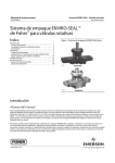
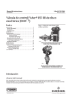
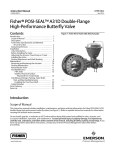
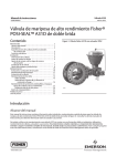
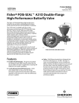
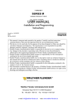
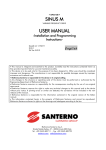
Instruction Manual
ENVIRO-SEAL System - Rotary Valves
D101643X012
November 2011
Fisherr ENVIRO-SEALt Packing System
for Rotary Valves
Contents
Introduction . . . . . . . . . . . . . . . . . . . . . . . . . . . . . . . . . 1
Scope of Manual . . . . . . . . . . . . . . . . . . . . . . . . . . . . . 1
Valve/Actuator Shaft Coupler . . . . . . . . . . . . . . . . . . 2
Description . . . . . . . . . . . . . . . . . . . . . . . . . . . . . . . . . 2
Installation . . . . . . . . . . . . . . . . . . . . . . . . . . . . . . . . . . 3
Removing the Actuator . . . . . . . . . . . . . . . . . . . . . . . 3
Installing an ENVIRO-SEAL Packing System . . . . . . . 4
Other Considerations . . . . . . . . . . . . . . . . . . . . . . . . 11
Parts Ordering . . . . . . . . . . . . . . . . . . . . . . . . . . . . . . . 13
Parts Kits . . . . . . . . . . . . . . . . . . . . . . . . . . . . . . . . . . . 13
Retrofit Kits . . . . . . . . . . . . . . . . . . . . . . . . . . . . . . . . 13
Repair Kits . . . . . . . . . . . . . . . . . . . . . . . . . . . . . . . . . 16
Figure 1. Typical ENVIRO-SEAL Packing System
W5882-1
W9058-1
ROTARY
BUTTERFLY
Introduction
Scope of Manual
This instruction manual includes installation and parts information for Fisher ENVIRO-SEAL live-loaded packing
systems (see figure 1). These systems are available for Fisher rotary valves with 12.7 through 88.9 mm (1/2 through
3-1/2 inch) shaft diameters. The system can be used with many rotary valves, as shown in tables 1 and 3. Refer to
appropriate valve and actuator instruction manuals for necessary information relating to the disassembly and
assembly of the valve and actuator. ENVIRO-SEAL packing systems utilize a Belleville (coned-disk) spring system.
Do not install, operate, or maintain the ENVIRO-SEAL packing system, valve, actuator or accessories without being
fully trained and qualified in valve, actuator, and accessory installation, operation, and maintenance. To avoid personal
injury or property damage, it is important to carefully read, understand, and follow all the contents of this manual,
including all safety cautions and warnings. If you have any questions about these instructions, contact your Emerson
Process Management sales office before proceeding.
www.Fisher.com
Instruction Manual
ENVIRO-SEAL System - Rotary Valves
November 2011
D101643X012
Table 1. Specifications
Applicable Valve Designs
Fisher 8510B (single arrangements only), 8560 and
8532 eccentric disc control valves; A11, A31A, A31D
and A41 control valves; V150, V200 and V300
Vee-Ballt control valves (Series B & Non-Series B(1));
V250 and V260 and BV500, CV500 and V500
eccentric plug rotary valves. Also see table 3.
Applicable Shaft Diameters
See table 3
Pressures and Temperatures(2)
See table 2
1. Refer to Fisher Vee-Ball V150, V200 & V300 instruction manual, for distinctions between Series B & Non-Series B.
2. The pressure/temperature limits in this manual, in the valve literature, and any applicable code or standard limitation should not be exceeded.
Table 2. Maximum Application Temperature and Pressure for 100 PPM Service
MAXIMUM APPLICATION TEMPERATURE
_C
_F
MAXIMUM APPLICATION
PRESSURE
Single PTFE
232
450
Not Restricted(1)
Double PTFE(2)
177
350
20.7 bar
(300 Psi)
Graphite
316
600
Not Restricted(1)
ENVIRO-SEAL PACKING MATERIAL
1. For pressure ratings through CL600 of valves listed in this instruction manual.
2. These application conditions apply for double PTFE only in the valve types where double PTFE is available.
Valve/Actuator Shaft Coupler
To install an ENVIRO-SEAL packing system on an A11, A31A, A31D, or 8532 valve with a non-standard, non-Fisher
produced actuator may require a special valve/actuator shaft coupler.
Table 10 contains a list of valve/actuator combinations and part numbers for the new coupler. If you are considering
installation of an ENVIRO-SEAL packing system in another existing valve/actuator package, check table 10 to see if a
new coupler is required.
In some cases, coupler replacement is not required when retrofitting valve/actuator combinations. Table 11 contains a
list of valve/actuator combinations that can use existing couplers.
Description
Fisher packing systems are offered with exceptional sealing capabilities that you can easily install in existing valves or
that you can purchase with new valves. These systems help you conserve valuable process fluid. The external
live-loading provides a constant load over the life of the packing material, which reduces the need for packing box
adjustment and maintenance.
The system design, coupled with very smooth shaft finishes and spring-loading of the packing, provides longer service
with lower maintenance than many other designs.
2
Instruction Manual
ENVIRO-SEAL System - Rotary Valves
D101643X012
November 2011
Installation
Use these instructions to install ENVIRO-SEAL packing in valves that have standard packing, or when inspecting or
replacing ENVIRO-SEAL packing.
If you are changing the packing system material from standard graphite to ENVIRO-SEAL graphite or ENVIRO-SEAL
PTFE packing, the packing friction for ENVIRO-SEAL packing will be lower than it was for the standard packing.
Therefore, no change should be needed in actuator sizing.
If you are changing the packing system material from standard PTFE to ENVIRO-SEAL graphite or ENVIRO-SEAL PTFE
packing, the packing friction will increase. Contact your Emerson Process Management sales office to determine if
your existing actuator will be large enough.
WARNING
Always wear protective gloves, clothing and eyewear when performing any maintenance operations to avoid personal
injury.
To avoid personal injury or property damage resulting from the sudden release of pressure, do not install the valve
assembly where service conditions could exceed the limits given in this manual, the appropriate valve instruction manual,
or the limits on the appropriate name plates. Use pressure relieving devices as required by government or accepted
industry codes and good engineering practices.
Check with your process or safety engineer for any additional measures that must be taken to protect against process
media.
If installing into an existing application, also refer to the WARNING at the beginning of the Removing the Actuator section
in this instruction manual.
Removing the Actuator
WARNING
Avoid personal injury from sudden release of process pressure or uncontrolled movement of parts. Before performing any
maintenance operations:
D Do not remove the actuator from the valve while the valve is still pressurized.
D Always wear protective gloves, clothing and eyewear when performing any maintenance operations to avoid personal
injury.
D Disconnect any operating lines providing air pressure, electric power, or a control signal to the actuator. Be sure the
actuator cannot suddenly open or close the valve.
D Use bypass valves or completely shut off the process to isolate the valve from process pressure. Relieve process pressure
on both sides of the valve. Drain the process media from both sides of the valve.
D Vent the power actuator loading pressure and relieve any actuator spring precompression.
D Use lock-out procedures to be sure that the above measures stay in effect while you work on the equipment.
D The valve packing box may contain process fluids that are pressurized, even when the valve has been removed from the
pipeline. Process fluids may spray out under pressure when removing the packing hardware or packing rings, or when
loosening the packing box pipe plug.
D Check with your process or safety engineer for any additional measures that must be taken to protect against process
media.
3
ENVIRO-SEAL System - Rotary Valves
Instruction Manual
November 2011
D101643X012
You must remove the actuator from the valve when you install ENVIRO-SEAL packing systems. To allow proper
readjustment of the valve disc position, it is recommended that you remove the valve from the pipeline. Refer to
appropriate valve and actuator instruction manuals.
WARNING
If a spring-return actuator is used, be sure the actuator spring is resting on its travel stop. If something is obstructing shaft
rotation, it is possible that disconnecting the shaft connector will allow the spring to force the actuator to the end of its
rotation, resulting in possible personal injury or property damage. Refer to the appropriate valve and actuator instruction
manuals to remove the actuator.
Installing an ENVIRO-SEAL Packing System
Note
When installing an ENVIRO-SEAL packing system into an insulated valve, do not cover the packing springs with insulation.
Note
The valve shaft surface condition is critical in obtaining a good seal. If the valve shaft surface is scratched, nicked, or worn, replace
the valve shaft before installing the ENVIRO-SEAL Packing System.
Refer to the appropriate valve instruction manual to replace the valve shaft.
Key number locations are shown in figures 2 and 4 for Vee-Ball, eccentric plug, 8560, and A41 valves, and in figures 3
and 5 for A11, A31A, A31D and 8532 valves.
1. If you are installing an ENVIRO-SEAL packing system in an existing valve, remove existing packing nuts, packing
flange, jam nuts, anti-blowout flange, packing follower, and any other external packing components from the valve
body.
CAUTION
Because the valve shaft surface condition is critical in obtaining a good seal, caution must be used when removing existing
internal packing parts. Do not scratch, nick or dent the valve shaft.
2. For A11, A31A, A31D and 8532 valves, remove the anti-blowout wire that surrounds the valve shaft.
3. For all valves, remove packing and all other internal components from the packing box.
4. Inspect the existing valve shaft. If necessary, replace the valve shaft. Refer to the appropriate valve instruction
manual to replace the valve shaft.
4
Instruction Manual
ENVIRO-SEAL System - Rotary Valves
D101643X012
November 2011
Figure 2. Typical ENVIRO-SEAL Rotary Packing Arrangements with PTFE Packing for Fisher Vee-Ball, Eccentric Plug,
A41, and 8560 Valves
42B8445-C
SINGLE PTFE PACKING
STANDARD DEPTH BOX
14B0095-A
STACKING ORDER
PTFE PACKING RINGS
42B8445-C
42B8445-C
SINGLE PTFE PACKING
OPTIONAL DEEP PACKING BOX
V500
DOUBLE PTFE PACKING WITH LEAKOFF
OPTIONAL DEEP PACKING BOX
V500, CV500
42B8445-C
SINGLE PTFE PACKING, OUTBOARD
STANDARD DEPTH BOX
8510B
NOTES:
1
2
APPLY LUBRICANT
THESE TWO SURFACES MUST REMAIN PARALLEL AS YOU ALTERNATELY AND EVENLY TIGHTEN THE PACKING NUTS (KEY 101)
5
ENVIRO-SEAL System - Rotary Valves
November 2011
Instruction Manual
D101643X012
Note
ENVIRO-SEAL PTFE packing systems can be used in either vacuum or positive pressure service. It is not necessary to reverse
ENVIRO-SEAL PTFE packing components in vacuum service.
Make sure that the Belleville springs are stacked properly and packing box parts are assembled in the correct order (see figure 6).
Packing parts cannot function properly if the Belleville springs or other packing parts are not stacked correctly.
5. With the shaft in place in the valve, install the packing parts into the valve packing box.
Note
Be sure to install the packing rings in the sequence shown in figures 2 through 5.
a. Place one of the packing box rings (key 107) into the packing box. Be sure the packing box ring is properly seated.
This does not apply to NPS 3, 4 and 6 CL600 A11 valves.
b. For PTFE packing, place an anti-extrusion washer (key 106) into the packing box and push it in until it rests next
to the packing box ring (key 106 is not used with graphite packing).
Note
The graphite packing set has a carbon anti-extrusion ring on the top and bottom of the packing. These anti-extrusion rings are
designed to have a slight interference fit on the shaft. The rings have a single fracture to allow the ring to be installed on the shaft.
Additional fractures may develop while the valve is in service, however, these additional fractures will not affect the performance
of the ENVIRO-SEAL packing.
c. Place the packing set (key 105) into the packing box. Refer to figure 3 or 5 for the proper orientation of the
packing set.
d. For PTFE packing, place another anti-extrusion washer (key 106) into the packing box after the packing set (key
106 is not used with graphite packing).
e. Place the second packing box ring (key 107) into the packing box.
f. Locate the new spring pack assembly (key 103). Remove the O-ring and packing springs from the packing
follower. Use the packing follower to press the packing components into the packing box. Remove the packing
follower.
6. For A11, A31A, A31D and 8532 valves, install the anti-blowout wire (key 16) in the groove around the valve shaft.
7. Slide the packing follower from the new spring pack assembly over the valve shaft and the anti-blowout wire until it
rests against the packing box ring.
8. For all valves, install the longer packing studs (key 100).
9. For A11, A31A, A31D and 8532 valves, install the new anti-blowout flange (key 10) over the valve shaft, packing
studs, and packing follower. Secure the anti-blowout flange with the new jam nuts (key 17).
10. For all valves, install the spring pack assembly (key 103 or 104) which includes the Belleville springs, packing
follower, and O-ring arranged as shown in figures 2 through 6. (The O-ring is a non-functional part and is used to
retain the packing springs during assembly.)
6
Instruction Manual
ENVIRO-SEAL System - Rotary Valves
D101643X012
November 2011
Figure 3. ENVIRO-SEAL PTFE Packing System for Fisher 8532, A11, A31A and A31D Valves
3
32B9116-B
NOTES:
1
2
3
14B0095-A
STACKING ORDER OF
PTFE PACKING RINGS
NOT USED ON VALVES LARGER THAN NPS 12
NOT USED ON A11
NOT USED ON A11 CL600, NPS 3, 4, AND 6
11. Install the packing flange (key 102) on the shaft, and install the packing nuts (key 101). Hand tighten them.
Note
In general, the following tightening procedure applies to all ENVIRO-SEAL packing systems–both sliding-stem and rotary.
CAUTION
Excessive force could cause valve body bushing displacement in Non-Series B Vee-Ball valves, allowing Vee-Ball
misalignment, excessive seat leakage, or stalling of the actuator.
Note
Lubrication is required for the packing studs and nuts. Although it is important to properly lubricate the stud threads and internal
nut threads, it is also important to properly lubricate the contacting face of the nut. See figures 2 through 5 and 7 for lubrication
locations.
7
Instruction Manual
ENVIRO-SEAL System - Rotary Valves
November 2011
D101643X012
Figure 4. Typical ENVIRO-SEAL Rotary Packing Arrangements with Graphite Packing for Fisher Vee-Ball, Eccentric
Plug, A41, and 8560 Valves
2
1
42B8445-C/DOC
GRAPHITE PACKING
STANDARD DEPTH BOX
2
3
3
3
2
14B0086-A/DOC
42B8445-C/DOC
STACKING ORDER
GRAPHITE PACKING RINGS
GRAPHITE PACKING, OUTBOARD
STANDARD DEPTH BOX
8510B
42B8445-C/DOC
GRAPHITE PACKING
OPTIONAL DEEP PACKING BOX
V500
NOTES:
1 APPLY LUBRICANT
2 THESE TWO SURFACES MUST REMAIN PARALLEL AS YOU ALTERNATELY AND
EVENLY TIGHTEN THE PACKING NUTS (KEY 101)
3 VALVE WITH SHAFTS LARGER THAN 38.1 mm (1-1/2 INCH) USE THREE GRAPHITE RINGS
Note the following definitions. You will need them for the next few steps. The target load is the point where the
Belleville springs are designed for optimum performance, when they are compressed to 85% of their maximum
deflection, or nearly flat. Maximum deflection is when the springs are 100% compressed, or completely flat.
12. You will obtain maximum benefit from your ENVIRO-SEAL packing system when you tighten the packing flange
nuts and compress the Belleville springs to their “target load”.
To obtain the target load of 85% compression of maximum deflection, perform the following:
D Tighten the packing flange nuts alternately and evenly, keeping the packing flange parallel with the valve flange
(see figure 7), until the Belleville springs are compressed 100% (or completely flat).
8
Instruction Manual
ENVIRO-SEAL System - Rotary Valves
D101643X012
November 2011
Figure 5. ENVIRO-SEAL Graphite Packing System for Fisher 8532, A11, A31A and A31D Valves
14B0086-A
STACKING ORDER OF
GRAPHITE PACKING RINGS
4
32B9116-B
NOTES:
1 VALVES WITH SHAFTS LARGER THAN 38.1 mm (1-1/2 INCH) USE 3 GRAPHITE RINGS
2 NOT USED ON VALVES LARGER THAN NPS 12
3 NOT USED ON A11 VALVES
4 NOT USED ON A11 CL600 NPS 3, 4, AND 6
CAUTION
Do not use pneumatic air tools. Do not apply torque in excess of 34 NSm (25 ftSlbs) increments to any one flange nut at a
time. Excessive over-torquing of the flange nuts may cause the studs to break.
D For PTFE packing, loosen each packing flange nut 1/2 turn (180_ of rotation).
D For graphite packing, loosen each packing flange nut 1/4 turn (90_ of rotation).
The “target load” of 85% compression has now been reached.
13. Install the actuator. Refer to the appropriate valve and actuator instruction manuals when connecting the valve to
the actuator.
Under normal conditions, the packing nuts should not require re-tightening.
However, when servicing, if the springs do not remain at the target load of 85% compression, retighten the packing
box nuts according to step 11 above.
9
Instruction Manual
ENVIRO-SEAL System - Rotary Valves
November 2011
D101643X012
Figure 6. Belleville Spring Stacking Order
O-RING
O-RING
BELLEVILLE
SPRINGS (10)
BELLEVILLE
SPRINGS (6)
PACKING
FOLLOWER
PACKING
FOLLOWER
GRAPHITE
A41, ECCENTRIC DISC, ECCENTRIC PLUG, AND VEEBALL VALVES: SIZE 12.7 & 15.9 (1/2 AND 5/8) SHAFT
A11 and A31A: SIZE 14.3 (9/16) SHAFT
GRAPHITE
A41, ECCENTRIC DISC, ECCENTRIC PLUG, AND VEEBALL VALVES: SIZE 19.1 (3/4), 38.1 (1-1/2), 44.5 (1-3/4), 53.8
(2-1/8), 63.5 (2-1/2), 76.2 (3) AND 88.9 (3-1/2) SHAFT
A11: SIZE 19.2 - 88.9 (3/4 - 3-1/2) SHAFT
A31A: SIZE 17.5 - 31.8 (11/16 - 1-1/4) SHAFT
O-RING
BELLEVILLE
SPRINGS (9)
PACKING
FOLLOWER
PTFE
A41, ECCENTRIC DISC, ECCENTRIC PLUG,
AND VEE-BALL VALVES:
SIZE 12.7 AND 15.9 (1/2 AND 5/8) SHAFT
A11 and A31A: SIZE 14.3 (9/16) SHAFT
B2410-2
10
O-RING
O-RING
BELLEVILLE
SPRINGS (7)
BELLEVILLE
SPRINGS (5)
PACKING
FOLLOWER
PTFE
A41, ECCENTRIC DISC, ECCENTRIC PLUG, AND
VEE-BALL VALVES:
SIZE 19.1 (3/4), 22.2 (7/8), AND 25.4 (1) SHAFT
A11: SIZE 14.3 AND 19.1 (9/16 AND 3/4) SHAFT
A31A: SIZE 17.5 AND 23.8 (11/16 AND 15/16) SHAFT
PACKING
FOLLOWER
PTFE
A41, ECCENTRIC DISC, ECCENTRIC PLUG, AND
VEE-BALL VALVES: SIZE 19.1 (3/4), 38.1 (1-1/2), 44.5
(1-3/4), 53.8 (2-1/8), 63.5 (2-1/2), 76.2 (3) AND 88.9 (3-1/2)
SHAFT
A11: SIZE 28.5 - 88.9 (1- 1/8 - 3-1/2) SHAFT
A31A: SIZE 28.5 - 63.5 (11/16 - 2-1/2) SHAFT
mm (INCH)
Instruction Manual
D101643X012
ENVIRO-SEAL System - Rotary Valves
November 2011
Figure 7. ENVIRO-SEAL PTFE Packing System Detail
32B9116-B
NOTES:
1 APPLY LUBRICANT
2 THESE TWO SURFACES MUST REMAIN PARALLEL AS YOU ALTERNATELY AND EVENLY TIGHTEN THE PACKING NUTS.
Other Considerations
Note
The following check is only valid for rotary ENVIRO-SEAL packing systems and sliding-stem ENVIRO-SEAL or HIGH-SEAL packing
systems.
When retrofitting an existing packing system or repacking a valve with ENVIRO-SEAL packing that has been in service,
check the condition of the packing bore after you have removed the packing. An easy method for cleaning debris and
minor imperfections from the bore is to use a brake cylinder hone attached to an electric drill. This method will do a
good job of cleaning the packing bore without changing the dimension of the bore.
When you have completed this exercise, a good guideline to use in checking the condition of the packing bore is the
20/20 rule. If less than 20% of the surface area of the bore is pitted and if no pits are deeper than 0.020 inch, then your
packing will work fine. This does not need to be an exact measurement; visual inspection is adequate. If the packing
bore does not meet this criteria, however, you should replace the valve or have your Emerson Process Management
service center repair it.
11
Instruction Manual
ENVIRO-SEAL System - Rotary Valves
November 2011
D101643X012
Table 3. Applicable Valve Sizes
and Shaft Diameters(1)
VALVE
VALVE SIZE,
NPS
8510B
2
3
4
6
8
10
12
8532
8560
V150
V200
V300
12
14
16
18
20
24
14
16
18
20
24
2
3
4
6
8
10
12
2
3
4
6
8
10
12
1
1-1/2
2
3
4
6
8
10
12
14
16
20
1
1-1/2
2
3
4
6
8
10
1
1-1/2
2
3
4
6
8
10
12
14
16
PRESSURE
CLASS
Table 3. Applicable Valve Sizes
and Shaft Diameters (cont.)
VALVE SHAFT DIAMETER
mm
Inches
See Bulletin
51.6:8560
12.7
15.9
19.1
25.4
31.8
31.8
38.1
1/2
5/8
3/4
1
1-1/4
1-1/4
1-1/2
150
34.9
38.1
44.5
50.8
63.5
1-3/8
1-1/2
1-3/4
2
2-1/2
300
50.8
57.2
63.5
76.2
88.9
2
2-1/4
2-1/2
3
3-1/2
150
12.7
12.7
15.9
19.1
25.4
31.8
38.1
1/2
1/2
5/8
3/4
1
1-1/4
1-1/2
300
12.7
15.9
19.1
25.4
31.8
38.1
44.5
1/2
5/8
3/4
1
1-1/4
1-1/2
1-3/4
12.7
15.9
15.9
19.1
19.1
25.4
31.8
31.8
38.1
44.5
54
63.5
1/2
5/8
5/8
3/4
3/4
1
1-1/4
1-1/4
1-1/2
1-3/4
2-1/8
2-1/2
12.7
15.9
15.9
19.1
19.1
25.4
31.8
31.8
1/2
5/8
5/8
3/4
3/4
1
1-1/4
1-1/4
12.7
15.9
15.9
19.1
19.1
25.4
31.8
31.8
38.1
44.5
54
1/2
5/8
5/8
3/4
3/4
1
1-1/4
1-1/4
1-1/2
1-3/4
2-1/8
150
150/300/
600
300
VALVE
BV500
CV500
V500
A31A & A31D
A41
A11
VALVE SIZE,
NPS
1
1-1/2
2
3
4
6
3
4
6
8
10
12
1
1-1/2
2
3
4
6
8
10
3
4
6
8
10
12
14
16
18
20
24
3
4
6
8
10
12
14
16
18
20
24
2
3
4
6
8
10
12
2
3
4
6
8
10
12
3
4
6
8
10
12
14
16
18
PRESSURE
CLASS
VALVE SHAFT DIAMETER
mm
Inches
15.9
15.9
15.9
15.9
25.5
25.5
25.4
31.8
38.1
38.1
44.5
53.8
5/8
5/8
5/8
5/8
1
1
1
1-1/4
1-1/2
1-1/2
1-3/4
2-1/8
150/300/
600
12.7
15.9
15.9
25.4
31.8
31.8
38.1
44.5
1/2
5/8
5/8
1
1-1/4
1-1/2
1-1/2
1-3/4
150
14.3
17.5
23.8
23.8
28.5
31.8
34.9
38.1
44.5
50.8
63.5
9/16
11/16
15/16
15/16
1-1/8
1-1/4
1-3/8
1-1/2
1-3/4
2
2-1/2
300
14.3
17.5
23.8
31.8
41.3
47.6
50.8
57.2
63.5
76.2
88.9
9/16
11/16
15/16
1-1/4
1-5/8
1-7/8
2
2-1/4
2-1/2
3
3-1/2
150
12.7
12.7
15.9
19.1
25.4
31.8
38.1
1/2
1/2
5/8
3/4
1
1-1/4
1-1/2
300
12.7
15.7
19.0
25.4
31.8
38.1
44.4
1/2
5/8
3/4
1
1-1/4
1-1/2
1-3/4
600
14.3
19.1
28.5
38.1
44.5
57.2
63.5
76.2
88.9
9/16
3/4
1-1/8
1-1/2
1-3/4
2-1/4
2-1/2
3
3-1/2
150/300
150/300/
600
1. Shaft Diameter through the packing box.
Instruction Manual
D101643X012
ENVIRO-SEAL System - Rotary Valves
November 2011
Parts Ordering
Each valve assembly is assigned a serial number that can be found on the valve body. Refer to the serial number when
contacting your Emerson Process Management sales representative for technical assistance.
When ordering replacement parts, refer to the serial number and to the 11-character kit number for each kit required
from the following list. Kits for valves with shaft sizes greater than 38.4 mm (1-1/2 inch) will not be available, however,
ENVIRO-SEAL parts may be ordered separately. Consult your Emerson Process Management sales office for details.
Parts Kits
Retrofit Kits
Retrofit kits include all parts required for installation of the ENVIRO-SEAL packing system into existing rotary and high
performance butterfly valves. Retrofit kits are available for single PTFE or graphite packing. See tables 5 through 7 for
retrofit kit part numbers.
The 8510B has two packing boxes, one at the actuator end and one at the outboard end. Select a kit from each column
of the following table.
Packing boxes in V500 and CV500 valve bodies may be deep drilled, (at one time standard on all CV500 and always
available as an option). If the valve body being retrofitted has a deep packing box, use the longer packing box ring (key
107) from the original packing. Discard the 3 mm (1/8-inch) packing box ring from the retrofit kit. If a replacement
packing box ring (long, key 107) is required, refer to the valve instruction manual for parts, or consult your Emerson
Process Management sales office. Refer to figure 2, the view titled: Double PTFE Packing with Leakoff–Optional Deep
Packing Box.
Note
1. Use the existing long packing box ring (key 107) that was furnished with the original valve when installing the retrofit kit in:
•V200 NPS 8 and 10 valves, or
•V150 and V300 NPS 8, 10, and 12 valves
WARNING
Use only genuine Fisher replacement parts. Components that are not supplied by Emerson Process Management should
not, under any circumstances, be used in any Fisher valve, because they may void your warranty, might adversely affect the
performance of the valve, and could cause personal injury and property damage.
13
Instruction Manual
ENVIRO-SEAL System - Rotary Valves
November 2011
D101643X012
Table 4. Retrofit Kit Included Parts
Key
Description
Quantity
10(5)
17(5)
100
Anti-blowout follower(5)
Jam nut(5)
Packing stud
2(6) or 4(7)
101
102
103
Packing nut
Packing flange
Spring pack assembly(1)
2(6) or 4(7)
1
1
104
105
106
Spring pack assembly(2)
Packing Set
Anti-extrusion washer
1
1
2(3)
107
111
112
Packing box ring
Tag
Cable
2(4)
1
1
1
1
1.For use on Actuator end. The spring pack assembly is made up of the packing spring stack held in place by an O-ring on the packing follower.
2. For use on Outboard end. The spring pack assembly is made up of the packing spring stack held in place by an O-ring on the packing follower.
3. Not included in graphite packing kit.
4. Only 1 req'd for NPS 18 CL300, NPS 20 CL150 and NPS 24 CL150. Two packing box rings required for 8560, 44.5 mm (1-3/4 inch) shaft. Not required on V150, V200 or V300 with 31.8 or 38.1
mm (1-1/4 or 1-1/2 inch) shafts.
5. These are included in retrofit kits for 8532, A11, A31A and A31D valves.
6. NPS 3 through 12 CL150 and NPS 3 through 8 CL300 for A31A, 8532 and A31D; NPS 3 through 6 CL600, A11.
7. NPS 14 through 24 CL150/300 for A31A, 8532 and A31D; NPS 8 through 18 CL600, A11.
Table 5. Retrofit Kits for Fisher Vee-Ball, Eccentric Plug, 8560 and 8510B Valves with Spline Shafts
PTFE RETROFIT KITS
PACKING BOX END
Outboard End for
Actuator End
8510B Only
GRAPHITE RETROFIT KITS
PACKING BOX END
Outboard End for
Actuator End
8510B Only
12.7 (1/2)
RRTYXRT0012
RRTYXRT0082
RRTYXRT0312
RRTYXRT0382
15.9 (5/8)
RRTYXRT0022
RRTYXRT0092
RRTYXRT0322
RRTYXRT0392
19.1 (3/4)
RRTYXRT0032
RRTYXRT0102
RRTYXRT0332
RRTYXRT0402
25.4 (1)
RRTYXRT0052
RRTYXRT0112
RRTYXRT0352
RRTYXRT0412
31.8 (1-1/4)
RRTYXRT0062
RRTYXRT0122
RRTYXRT0362
RRTYXRT0422
38.1 (1-1/2)
8560 NPS 10 (CL 300)
8560 NPS 12 (CL 150)
RRTYXRT0072
RRTYXRT0672
RRTYXRT0672
RRTYXRT0132
-----
RRTYXRT0372
RRTYXRT0812
RRTYXRT0812
RRTYXRT0432
-----
44.5 (1-3/4)
8560 NPS 12 (CL 300)
V500 NPS 10
RRTYXRT0682
RRTYXRT0692
RRTYXRT0702
RRTYXRT0762
-----
RRTYXRT0822
RRTYXRT0832
RRTYXRT0842
RRTYXRT0902
-----
54 (2-1/8)
RRTYXRT0722
---
RRTYXRT0862
---
63.5 (2-1/2)
RRTYXRT0732
RRTYXRT0782
RRTYXRT0872
RRTYXRT0922
SHAFT DIAMETER, mm (INCH)
Table 6. Retrofit Kits for Fisher Vee-Ball, Eccentric Plug, 8510B and A41 valves with Double D and Keyed End
Connection
PTFE RETROFIT KITS PACKING BOX END
SHAFT DIAMETER, mm (INCH)
Actuator End
Outboard End for
8510B Only
GRAPHITE RETROFIT KITS PACKING BOX END
Actuator End
Outboard End for
8510B Only
Double D
12.7 (1/2)
RRTYXRT0972
RRTYXRT0082
RRTYXRT1072
RRTYXRT0382
15.9 (5/8)
RRTYXRT0982
RRTYXRT0092
RRTYXRT1082
RRTYXRT0392
19.1 (3/4)
RRTYXRT0992
RRTYXRT0102
RRTYXRT1092
RRTYXRT0402
25.4 (1)
RRTYXRT1012
RRTYXRT0112
RRTYXRT1102
RRTYXRT0412
31.8 (1-1/4)
RRTYXRT1022
RRTYXRT0122
RRTYXRT1112
RRTYXRT0422
38.1 (1-1/2)
RRTYXRT1032
RRTYXRT0132
RRTYXRT1122
RRTYXRT0432
44.5 (1-3/4)
RRTYXRT1042
RRTYXRT0762
RRTYXRT1132
RRTYXRT0902
Keyed
14
54 (2-1/8)
RRTYXRT1052
---
RRTYXRT1142
---
63.5 (2-1/2)
RRTYXRT1062
RRTYXRT0782
RRTYXRT1152
RRTYXRT0922
Instruction Manual
ENVIRO-SEAL System - Rotary Valves
D101643X012
November 2011
Table 7. Retrofit Kit Part Numbers for Fisher 8532, A31A, A31D and A11 Butterfly Valves
8532, A31A, A31D
PTFE
Graphite
150, 300
Shaft
Diameter(1)(2),
mm (Inch)
14.3 (9/16)
RRTYXRT0202
RRTYXRT0502
4
150, 300
17.5 (11/16)
RRTYXRT0212
RRTYXRT0512
6
150, 300
23.8 (15/16)
RRTYXRT0222
RRTYXRT0522
150
23.8 (15/16)
RRTYXRT0232
RRTYXRT0532
300
31.8 (1-1/4)
RRTYXRT0242
RRTYXRT0542
150
28.5 (1-1/8)
RRTYXRT0252
RRTYXRT0552
300
41.3 (1-5/8)
RRTYXRT0572
---
150
31.8 (1-1/4)
RRTYXRT0262
RRTYXRT0562
300
47.6 (1-7/8)
RRTYXRT0582
150
34.9 (1-3/8)
RRTYXRT0592
300
50.8 (2)
RRTYXRT0602
150
38.1 (1-1/2)
RRTYXRT0612
300
57.2 (2-1/4)
RRTYXRT0622
150
44.5 (1-3/4)
RRTYXRT0632
Valve Size, NPS
Pressure Class
3
8
10
12
14
16
18
Retrofit Kits
---
300
63.5 (2-1/2)
RRTYXRT0642
20
150
50.8 (2)
RRTYXRT0652
24
150
63.5 (2-1/2)
RRTYXRT0662
Shaft Diameter
PTFE Retrofit
Kits
Graphite
Retrofit Kits
3
14.3 (9/16)
12B4122X012
12B4125X012
4
19.1 (3/4)
14B3988X012
14B3989X012
6
28.6 (1-1/8)
12B4105X012
12B4107X012
8
38.1 (1-1/2)
13B9289X012
14B3985X012
44.5 (1-3/4)
13B9285X012
13B9286X012
12
57.2 (2-1/4)
14B1323X012
14B3978X012
14
63.5 (2-1/2)
12B4111X012
12B4116X012
16
76.2 (3)
14B5651X022
14B5660X022
18
88.9 (3-1/2)
14B5729X042
14B5736X042
A11
Valve Size, NPS
10
Pressure Class
600
1. Shaft diameter: Diameter through the packing box.
2. For larger shaft sizes, consult your Emerson Process Management sales office.
15
Instruction Manual
ENVIRO-SEAL System - Rotary Valves
November 2011
D101643X012
Repair Kits
PTFE repair kits include one packing set and two anti-extrusion washers. Graphite packing sets include two packing
rings and two anti-extrusion rings. See table 8.
The 8510B has two packing boxes, one at the actuator end and one at the outboard end. A quantity of two of the
appropriate kit is required to repair both ends.
WARNING
Use only genuine Fisher replacement parts. Components that are not supplied by Emerson Process Management should
not, under any circumstances, be used in any Fisher valve, because they may void your warranty, might adversely affect the
performance of the valve, and could cause personal injury and property damage.
Table 8. Repair Kits for Fisher Vee-Ball, Eccentric Plug, 8560, 8510B and A41 Valves
16
Shaft Diameter mm (Inch)
PTFE Kits
Graphite Packing Set
12.7 (1/2)
15.9 (5/8)
19.1 (3/4)
25.4 (1)
31.8 (1-1/4)
RRTYX000012
RRTYX000022
RRTYX000032
RRTYX000052
RRTYX000062
13B8816X012
13B8816X032
13B8816X052
13B8816X092
13B8816X112
38.1 (1-1/2)
44.5 (1-3/4)
RRTYX000072
RRTYX000232
13B8816X142
13B8816X152
54.0 (2-1/8)
63.5 (2-1/2)
RRTYX000252
RRTYX000262
13B8816X182
13B8816X162
Instruction Manual
ENVIRO-SEAL System - Rotary Valves
D101643X012
November 2011
Table 9. Repair Kit Part Numbers for Fisher 8532, A31A, A31D and A11 Butterfly Valves
8532, A31A, A31D
Valve Size,
NPS
Pressure Class
3
150, 300
Shaft
Diameter(1)(2),
mm (Inch)
14.3 (9/16)
4
150, 300
17.5 (11/16)
RRTYX000122
13B8816X042
6
150, 300
23.8 (15/16)
RRTYX000132
13B8816X082
150
23.8 (15/16)
RRTYX000132
13B8816X082
300
31.8 (1-1/4)
RRTYX000142
13B8816X122
150
28.5 (1-1/8)
RRTYX000092
13B8816X102
300
41.3 (1-5/8)
RRTYX000152
---
150
31.8 (1-1/4)
RRTYX000142
13B8816X122
300
47.6 (1-7/8)
RRTYX000162
150
34.9 (1-3/8)
RRTYX000172
300
50.8 (2)
RRTYX000182
150
38.1 (1-1/2)
RRTYX000192
300
57.2 (2-1/4)
RRTYX000202
150
44.5 (1-3/4)
RRTYX000212
8
10
12
14
16
18
Repair Kits
PTFE
Graphite Packing Set
RRTYX000112
13B8816X022
300
63.5 (2-1/2)
RRTYX000222
20
150
50.8 (2)
RRTYX000182
24
150
63.5 (2-1/2)
---
RRTYX000222
A11
Shaft Diameter
PTFE Packing Kits
AntiExtrusion Ring(3)
Graphite Packing
Kits
3
14.3 (9/16)
12B9122X012
12B9121X012
13B8816X022
12B9118X012
4
19.1 (3/4)
12B7414X012
12B7418X012
13B8816X052
16A6084X012
6
28.6 (1-1/8)
12B9078X012
12B9084X012
13B8816X102
12B9077X012
8
38.1 (1-1/2)
12B7462X012
12B7466X012
13B8816X142
16A6087X012
Valve Size, NPS
10
Pressure Class
Packing Box Ring
44.5 (1-3/4)
13B9155X012
13B9159X012
14B3541X032
13B9160X012
12
57.2 (2-1/4)
14B3647X012
14B3642X012
14B3541X052
13B2187X012
14
63.5 (2-1/2)
12B7782X012
12B7783X012
14B3541X042
13B8709X012
16
76.2 (3)
14B5652X012
14B5656X012
14B3541X062
18A4189X012
18
88.9 (3-1/2)
14B5730X012
14B5734X012
14B3541X072
14B5735X012
600
1. Shaft diameter: Diameter through the packing box.
2. For larger shaft sizes, consult your Emerson Process Management sales office.
3. The A11 requires 2 Anti-Extrusion Rings.
17
Instruction Manual
ENVIRO-SEAL System - Rotary Valves
November 2011
D101643X012
A coupler is required for the following valve/actuator combinations when retrofitting an existing A31A or A31D with an
ENVIRO-SEAL packing system.
Table 10. Coupler Part Number for Fisher A31A or A31D Valves with Selected Actuators
SHAFT DIAMETER,
mm (INCH)
Valve Size
Actuator Type
Coupler
Part No.
14.3 (9/16)
NPS 3 CL150/300
NPS 3 CL150/300
NPS 3 CL150/300
Fisher 1032 XL70 thru XL280
Fisher 1032 XL425 thru XL680
D and S Series (Elomatic) SR15
13B1596X012
13B1907X012
13B1595X012
17.5 (11/16)
NPS 4 CL150/300
NPS 4 CL150/300
NPS 4 CL150/300
NPS 4 CL150/300
Fisher 1032 XL185 thru XL280
Fisher 1032 XL425 thru XL680
Bettis HD 521, 721, 722
D and S Series (Elomatic) S20
13B1600X012
13B1908X012
13B1597X012
13B1599X012
23.8 (15/16)
NPS 6 CL150/300, NPS 8 CL150
NPS 6 CL150/300, NPS 8 CL150
NPS 6 CL150/300, NPS 8 CL150
NPS 6 CL150/300, NPS 8 CL150
NPS 6 CL150/300, NPS 8 CL150
NPS 6 CL150/300, NPS 8 CL150
NPS 6 CL150/300, NPS 8 CL150
NPS 6 CL150/300, NPS 8 CL150
NPS 6 CL150/300, NPS 8 CL150
NPS 6 CL150/300, NPS 8 CL150
NPS 6 CL150/300, NPS 8 CL150
NPS 6 CL150/300, NPS 8 CL150
NPS 6 CL150/300, NPS 8 CL150
NPS 6 CL150/300, NPS 8 CL150
Fisher 1031 Size 26
Fisher 1031 Size 33
Fisher 1032 XL680-XL1370
5M Gear
Bettis CB 315
Bettis CB 415
Bettis CB 420
Bettis CB 520
Bettis CB 525
Bettis CB 725
Bettis HD 251.5
Bettis HD 521, 721, 722
Fire Sentry
Limitorque T-100
13B1610X012
13B1611X012
13B1613X012
13B1601X012
13B1602X012
13B1905X012
13B1605X012
13B1906X012
13B1604X012
13B1606X012
13B1609X012
13B1603X012
13B1608X012
13B1607X012
28.5 (1-1/8)
NPS 10 CL150
NPS 10 CL150
NPS 10 CL150
NPS 10 CL150
NPS 10 CL150
NPS 10 CL150
NPS 10 CL150
NPS 10 CL150
Fisher 1031 Size 26
Fisher 1031 Size 33
Fisher 1032 XL680-XL1370
Bettis CB 525
Bettis CB 725
Bettis HD 521, 721, 722
Fire Sentry
Limitorque T-100
13B1620X012
13B1621X012
13B1624X012
13B1614X012
13B1617X012
13B1615X012
13B1619X012
13B1618X012
31.8 (1-1/4)
NPS 8 CL300, NPS 12 CL150
NPS 8 CL300, NPS 12 CL150
NPS 8 CL300, NPS 12 CL150
NPS 8 CL300, NPS 12 CL150
NPS 8 CL300, NPS 12 CL150
NPS 8 CL300, NPS 12 CL150
NPS 8 CL300, NPS 12 CL150
NPS 8 CL300, NPS 12 CL150
NPS 8 CL300, NPS 12 CL150
NPS 8 CL300, NPS 12 CL150
NPS 8 CL300, NPS 12 CL150
Fisher 1031 Size 26
Fisher 1031 Size 33
Fisher 1032 XL680 - XL1370
Bettis CB 525
Bettis CB 725
Bettis HD 521, 721, 722
150 Bettis HD 731, 732
D and S Series (Elomatic) SR110
Limitorque SMB-000-5-HOBC
Limitorque T-250
Rotork 250
13B1081X012
13B1082X012
13B1086X012
13B1073X012
13B1077X012
13B1074X012
13B1075X012
13B1076X012
13B1084X012
13B1246X012
13B1079X012
18
Instruction Manual
ENVIRO-SEAL System - Rotary Valves
D101643X012
November 2011
The existing couplers, listed below, can accommodate a retrofit with an ENVIRO-SEAL packing system. Coupler
replacement is not required when retrofitting the valve/actuator combinations listed below. For information about
couplers for the A11 CL600 valves, contact your Emerson Process Management sales office.
Table 11. Coupler Part Number for Fisher A31A or A31D Valves with Selected Actuators
SHAFT DIAMETER,
mm (INCH)
Valve Size
Actuator Type
Coupler
Part No.
14.3 (9/16)
NPS 3 CL150/300
NPS 3 CL150/300
NPS 3 CL150/300
NPS 3 CL150/300
Bettis CB 315
Bettis CB 415
Bettis CB 420
Bettis CB 520
V160124X012
V160125X012
V151828X012
V154549X012
17.5 (11/16)
NPS 4 CL150/300
NPS 4 CL150/300
NPS 4 CL150/300
NPS 4 CL150/300
Bettis CB 315
Bettis CB 415
Bettis CB 420
Bettis CB 520
V160108X012
V160107X012
V151731X012
V154600X012
28.5 (1-1/8)
NPS 10 CL150
NPS 10 CL150
Bettis CB 420
Bettis CB 520
V160209X012
V160212X012
31.8 (1-1/4)
NPS 8 CL300, NPS 12 CL150
NPS 8 CL300, NPS 12 CL150
Bettis CB 420
Bettis CB 520
V160208X012
V160213X012
19
ENVIRO-SEAL System - Rotary Valves
November 2011
Instruction Manual
D101643X012
Neither Emerson, Emerson Process Management, nor any of their affiliated entities assumes responsibility for the selection, use or maintenance
of any product. Responsibility for proper selection, use, and maintenance of any product remains solely with the purchaser and end user.
Fisher, ENVIRO-SEAL, and Vee-Ball are marks owned by one of the companies in the Emerson Process Management business division of Emerson Electric Co.
Emerson Process Management, Emerson, and the Emerson logo are trademarks and service marks of Emerson Electric Co. All other marks are the property
of their respective owners.
The contents of this publication are presented for informational purposes only, and while every effort has been made to ensure their accuracy, they are not
to be construed as warranties or guarantees, express or implied, regarding the products or services described herein or their use or applicability. All sales are
governed by our terms and conditions, which are available upon request. We reserve the right to modify or improve the designs or specifications of such
products at any time without notice.
Emerson Process Management
Marshalltown, Iowa 50158 USA
Sorocaba, 18087 Brazil
Chatham, Kent ME4 4QZ UK
Dubai, United Arab Emirates
Singapore 128461 Singapore
www.Fisher.com
20
EFisher Controls International LLC 1991, 2011; All Rights Reserved