1
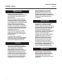
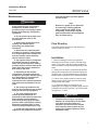
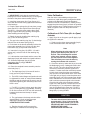
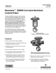
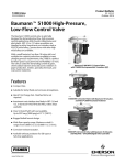
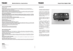
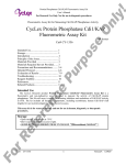
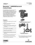
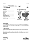
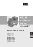
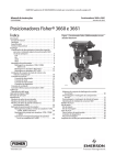
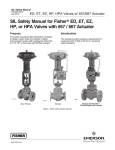
Instruction Manual
D103370X012
June 2010
84000 Valve
Baumannt 84000 Sanitary Diaphragm
Angle and Inline Control Valve
Contents
Introduction . . . . . . . . . . . . . . . . . . . . . . . . . . . . . . . . . 1
Scope of Manual . . . . . . . . . . . . . . . . . . . . . . . . . 1
Safety Precautions . . . . . . . . . . . . . . . . . . . . . . . . 2
Maintenance . . . . . . . . . . . . . . . . . . . . . . . . . . . . . . 3
Flow Direction . . . . . . . . . . . . . . . . . . . . . . . . . . . . . 3
Installation . . . . . . . . . . . . . . . . . . . . . . . . . . . . . . . . 3
Air Piping . . . . . . . . . . . . . . . . . . . . . . . . . . . . . . . . 4
Valve Body Removal . . . . . . . . . . . . . . . . . . . . . . 4
Actuator Removal . . . . . . . . . . . . . . . . . . . . . . . . 4
Bonnet Disassembly . . . . . . . . . . . . . . . . . . . . . . 4
Bonnet Reassembly . . . . . . . . . . . . . . . . . . . . . . 4
Valve Calibration . . . . . . . . . . . . . . . . . . . . . . . . . 5
Parts Ordering . . . . . . . . . . . . . . . . . . . . . . . . . . . . . 6
Dimensions and Weights . . . . . . . . . . . . . . . . . . 11
W9838
Figure 1. 84000 Inline Sanitary Valve
with Baumann 32 Actuator
Introduction
The Baumann 84000 sanitary control valve (figures
1, 2, and 3) is designed to satisfy the stringent
demands of the pharmaceutical and biotechnology
industries. These valves are in compliance with 3A
Sanitary Standards, Inc. requirements.
W9839
Scope of Manual
Figure 2. 84000 Angle Sanitary Valve with Baumann 32
Actuator and FIELDVUEt DVC2000 Digital Valve Controller
This instruction manual includes installation,
maintenance, and parts information for the Baumann
84000 sanitary control valve.
Do not install, operate, or maintain Baumann 84000
control valves without being fully trained and
qualified in valve, actuator, and accessory
installation, operation, and maintenance. To avoid
personal injury or property damage, it is important to
carefully read, understand, and follow all the
contents of this manual, including all safety cautions
and warnings. If you have any questions about these
instructions, contact your Emerson Process
Management sales office before proceeding.
www.Fisher.com
W9840
Figure 3. 84000 Angle Sanitary Valve with Baumann 54
Actuator and FIELDVUE DVC6000 Digital Valve Controller
Instruction Manual
84000 Valve
WARNING
Always wear protective gloves,
clothing and eyewear when performing
any installation operations to avoid
personal injury.
Personal injury or property damage
caused by sudden release of pressure
or bursting of pressure retaining parts
may result if service conditions exceed
those for which the product was
intended. To avoid injury or damage,
provide a relief valve for over pressure
protection as required by government
or accepted industry codes and good
engineering practices.
Check with your process or safety
engineer for any additional measures
that must be taken to protect against
process media.
If installing into an existing
application, also refer to the WARNING
at the beginning of the Maintenance
section in this instruction manual.
CAUTION
This valve is intended for a specific
range of pressures, temperatures and
other application specifications.
Applying different pressures and
temperatures to the valve could result
in parts damage, malfunction of the
control valve or loss of control of the
process. Do not expose this product to
service conditions or variables other
than those for which the product was
intended. If you are not sure what
2
June 2010
these conditions are you should
contact your Emerson Process
Management sales office for more
complete specifications. Provide the
product serial numbers (shown on the
nameplate) and all other pertinent
information.
WARNING
If you move or work on an actuator
installed on a valve with loading
pressure applied, keep your hands and
tools away from the stem travel path to
avoid personal injury. Be especially
careful when removing the stem
connector to release all loading on the
actuator stem whether it be from air
pressure on the diaphragm or
compression in the actuator springs.
Likewise take similar care when
adjusting or removing any optional
travel stop. Refer to the relevant
actuator Maintenance Instructions.
If hoisting the valve, take care to
prevent people from being injured in
case the hoist or rigging slips. Be sure
to use adequate sized hoists and
chains or slings to handle the valve.
WARNING
Personal injury could result from
packing leakage. Valve packing is
tightened before shipment; however,
the packing might require some
readjustment to meet specific service
conditions.
Instruction Manual
84000 Valve
June 2010
that must be taken to protect against
process media.
Maintenance
WARNING
Avoid personal injury and property
damage from sudden release of
process pressure or bursting of parts.
Before performing any maintenance
operations:
D Do not remove the actuator from
the valve while the valve is still
pressurized.
D Always wear protective gloves,
clothing, and eyewear when
performing any maintenance
operations.
D Disconnect any operating lines
providing air pressure, electric power,
or a control signal to the actuator. Be
sure the actuator cannot suddenly
open or close the valve.
D Use bypass valves or completely
shut off the process to isolate the
valve from process pressure. Relieve
process pressure on both sides of the
valve. Drain the process media from
both sides of the valve.
D Depending on the actuator
construction, it will be necessary to
manage the pneumatic actuator spring
precompression. It is essential to
refer to the relevant actuator
instructions in this manual to perform
safe removal of the actuator from the
valve.
D Use lock-out procedures to be
sure the above measures stay in effect
while you work on the equipment.
D The valve packing box may
contain process fluids that are
pressurized, even when the valve has
been removed from the pipeline.
Process fluids may spray out under
pressure when removing the packing
hardware or packing rings, or when
loosening the packing box pipe plug.
D Check with your process or safety
engineer for any additional measures
Note
Whenever a gasket seal is disturbed
by removing or shifting gasketed
parts, install a new gasket during
reassembly. This provides a good
gasket seal because the used gasket
may not seal properly.
Flow Direction
The preferred flow direction for selfdraining is
shown in figures 8 and 9.
Installation
1. Before installing the valve in the pipeline,
thoroughly clean the line of all dirt, welding chips,
scale, oil or grease, and other foreign material. A
micron size filter is recommended upstream of the
valve.
2. Install valve so that the controlled fluid will flow
through the valve body in the direction selected in
figures 8 and 9. The leak detection port should be
located at the lowest point in the installed position.
3. A threevalve bypass must be used to permit
removal of the control valve from the line without
shutting down the system.
4. To detect if leakage or breakage of the
diaphragm has occurred, a pressure gauge may be
installed in the 1/8 NPT port (key 14) in the bonnet,
see figures 4, 5, and 6.
WARNING
To avoid personal injury or property
damage, do not attempt to do any work
on a valve while the system is in
operation, the valve must be isolated
100% from the active system and the
isolated line voided of pressure and/or
hazardous fluids.
3
Instruction Manual
84000 Valve
June 2010
Air Piping
Actuator Removal
1. For an airtoextend actuator (airtoclose
action), connect the actuating air pressure line to the
1/4 NPT opening in the upper diaphragm case. For
an airtoretract actuator (airtoopen action)
connect the actuating air pressure line to the 1/4
NPT in the lower diaphragm case.
To remove the actuator, unscrew the drive nut
(key 9) and loosen the jam nuts (key 27). Unscrew
the piston stem (key 3) from the actuator stem.
2. Use 6.4 mm (1/4 inch) O.D. tubing or equivalent
for all air lines. If the air line exceeds 8 m (25 ft) in
length, 9.5 mm (3/8 inch) tubing is preferred. Air
lines must not leak. Air pressure should not exceed
2.5 bar (35 psig).
Valve Body Removal
CAUTION
Avoid personal injury or property
damage from sudden release of
pressure or bursting of parts. Remove
the actuator before attempting to
disassemble the valve.
Bonnet Disassembly
Reference figures 4, 5, and 6.
(Not Required For Actuator Reversal)
Actuator Removed
For field replacement of the diaphragm (key 8),
follow steps 1 through 4 below.
Remove the diaphragm (key 8) and the bonnet
Oring (key 15) (NPS 11/2 and 2 valves only) per
instructions under the previous Valve Body Removal
section. Proceed as follows:
Note
Do not squeeze the valve body in a
vise.
1. For failclosed action (airtoopen), stroke the
actuator up to take pressure off from the diaphragm
pushing against seat. For failopen action
(airtoclose), there is no need to stroke actuator.
2. Remove the bonnet screws (key 18) for NPS 1
valves or the clamp (key 11) for NPS 11/2 or 2
valves.
3. Lift the bonnet assembly (key 2) with the actuator
from the valve body (key 1).
4. Once disassembled; for failclosed action ONLY,
release pressure from the actuator to be able to
unscrew the diaphragm, for failopen action you
must pressurize the actuator to unscrew the
diaphragm. This is the only action required for
inspection or cleaning.
1. Turn over the bonnet assembly (key 2).
2. Pry out the retaining ring (key 7) using a small flat
screwdriver.
3. Remove the wave springs (key 6), compressor
(key 5) and drive mechanism (key 4).
4. Push out the pistonstem assembly (key 3).
Clean and replace as required.
Note
For NPS 11/2 & 2 valves, measure the
gap between the free ends of the
clamp (key 11) and return to this
position upon reassembly to minimize
change in zero calibration.
Bonnet Reassembly
Actuator Removed
5. Stroke the actuator down to exert some pressure
and remove the diaphragm (key 8) by unscrewing
the diaphragm (key 8) from the compressor (key 5).
Remove the bonnet Oring (key 15) (NPS 11/2 and
2 valves only). Wipe the diaphragm (key 8) with a
clean soft cloth and examine for wear.
For correct orientation of the subassemblies to the
bonnet refer to figure 7, exploded view.
6. Inspect the valve body sealing surfaces. If valve
leakage becomes excessive, replacement of the
diaphragm (key 8) may be necessary.
3. Verify that the machined surfaces at the end of
the rectangular plates are in full contact with the
machined recess inside the bonnet (key 2).
4
1. Insert the piston stem assembly (key 3) into the
bonnet (key 2).
2. Orient the drive mechanism as shown in figure 7.
Instruction Manual
84000 Valve
June 2010
4. IMPORTANT: Verify that the recessed roller
bearings in the drive mechanism (key 4) rest against
the flats of the piston stem assembly (key 3).
5. Install the compressor (key 5) per figures 4, 5,
and 6 with the flat side resting against the extended
roller bearings.
6. Drop the wave springs (key 6) into place, prongs
down; the NPS 1 valve requires two wave springs.
The NPS 11/2 and 2 valves require three wave
springs. Oppose the spring opening 180 degrees
when installing the wave springs.
7. Retain all parts by installing the retaining ring
(key 7) into the bonnet groove.
8. The gap in the retaining ring (key 7) should align
with the crest of the wave spring (key 6).
9. Push down on the bonnet assembly to drive the
piston stem assembly (key 3) firmly into the drive
mechanism (key 4) to provide some tension.
10. Insert the Oring (key 15) (NPS 11/2 and 2
valves only), so that it rests on the retaining ring
(key 7).
11. Lubricate the screw thread and the cone of the
diaphragm (key 8) with sterile food grade lubricant.
12. Screw the diaphragm (key 8) onto the
compressor (key 5) snugly. DO NOT
OVERTIGHTEN.
13. Place the complete bonnet assembly onto the
valve body (key 1).
a. The diaphragm (key 8) rim must fit into the
body groove for proper centering.
b. The NPS 1 bolted flange configuration should
be tightened for metaltometal contact between
the flange and the valve body. Be sure to use 45
lbfSft when tightening the valve body bolts on the
NPS 1 valve.
c. For NPS 11/2 and 2 valves, apply the clamp
(key 11) and tighten the nut gradually, checking
for an even amount of PTFE over the valve body,
between the bonnet and clamp, for proper
centering.
Valve Calibration
After the valve is assembled per the previous
instructions, install the properly configured actuator
(reference the Baumann Pneumatic Actuators
instruction manual, D103352X012), making sure to
engage the piston stem (key 3) as much as possible
into the actuator stem. Tighten the drive nut (key 9).
(Refer to figures 8 and 9 for the preferred flow
direction.)
Calibration of FailClose (AirtoOpen)
Actuator
1. Apply 50 psi air or nitrogen to port B. Apply 3 psi
air signal to the actuator.
a. Slowly turn the piston stem assembly (key 3)
out of the actuator stem until flow stops.
Note
When adjusting the valve stem, do not
grip the stem directly with pliers or a
wrench. This will damage the surface
of the stem. Instead, countertighten
the two locknuts on the stem together.
This will allow you to turn the stem by
turning the locknuts with a wrench.
b. Check the valve for leaks with 50 psi air under
the diaphragm (port B). Leakage should be less
than 1 cc/min. The valve should start to leak or
low flow at a minimum pressure signal to the
actuator. If it takes more than minimum pressure
to open, then screw the piston stem assembly
(key 3) further into the actuator stem. If the valve
is not tight at 3 psi signal, screw the piston stem
assembly (key 3) out of the actuator stem further.
Next, calibrate Zero on the travel indicator scale
with a minimum pressure signal to the actuator.
Check for full travel at the maximum pressure
signal. If the leak persists, increase the force on
the clamp (key 11) to compress the diaphragm
(key 8) by tightening the clamp nut. For NPS 1
valves, tighten the bolts (key 18) on the bonnet
flange (key 11) using 45 lbfSft.
CAUTION
d. The gap between the clamp ends should be
approximately 1/2 inch or less for proper
diaphragm compression. DO NOT
OVERTIGHTEN THE CLAMP.
e. Examine through port B to ensure the
diaphragm is centered on the seating area.
The stem should travel below zero by
approximately 1/16 to 1/8 inch after the
signal is decreased below 3 psi. IF THE
VALVE DOES NOT CLOSE PROPERLY,
INCREASE THE CLAMP
COMPRESSION AROUND THE
5
Instruction Manual
84000 Valve
DIAPHRAGM (key 8) by tightening 1/2
turn. DO NOT tighten to the point that
the diaphragm wrinkles.
Calibration of FailOpen (AirtoClose)
Actuator
2. Apply 50 psi air pressure or nitrogen to port B.
Apply 15 psi air signal to actuator.
a. Slowly turn the piston stem assembly (key 3)
out of the actuator stem until flow stops.
b. Check the valve for leaks with 50 psi air under
the diaphragm (port B). Leakage should be less
than 1 cc/min. The valve should start to leak or
low flow at a maximum pressure signal to the
actuator. If it takes more than the maximum
pressure to open, then screw the pistonstem
(key 3) further into the actuator stem. If the valve
is not tight at 15 psi signal, screw the pistonstem
(key 3) out of the actuator stem further. Next,
calibrate Zero on the travel indicator scale with
maximum pressure signal to the actuator. Check
for full travel at minimum pressure signal. If the
leak persists, increase the force on the clamp
(key 11) to compress the diaphragm (key 8) by
tightening the clamp nut. For NPS 1 valves,
tighten the bolts (key 18) on the bonnet flange
(key 11) using 45 lbfSft.
CAUTION
The stem should travel below zero by
approximately 1/16 to 1/8 inch after the
signal is increased above 15 psi. IF
THE VALVE DOES NOT CLOSE
PROPERLY, INCREASE THE CLAMP
COMPRESSION AROUND THE
DIAPHRAGM (key 8) by tightening 1/2
turn. DO NOT tighten to the point that
the diaphragm wrinkles.
6
June 2010
Note
When using a Baumann 32 actuator
with dual stops or a Baumann 54
actuator, the shaft collar (key 25) can
also be set at intermediate positions to
provide a minimum opening valve
travel stop.
Parts Ordering
When corresponding with your Emerson Process
Management sales office about this equipment,
always mention the valve serial number. When
ordering replacement parts, also specify the key
number, part name, and desired material using the
following parts tables.
WARNING
Use only genuine Fisherr replacement
parts. Components that are not
supplied by Emerson Process
Management should not, under any
circumstances, be used in any Fisher
valve, because they may void your
warranty, might adversely affect the
performance of the valve, and could
cause personal injury and property
damage.
Note
Neither Emerson, Emerson Process
Management, nor any of their affiliated
entities assumes responsibility for the
selection, use, or maintenance of any
product. Responsibility for the
selection, use, and maintenance of any
product remains with the purchaser
and end user.
Instruction Manual
84000 Valve
June 2010
E1314
Figure 4. Baumann 84000 NPS 1 Angle Valve Body
SubAssembly
E1316
Figure 6. Baumann 84000 NPS 11/2 and 2 Angle Valve
Body SubAssembly
E1315
E1317
Figure 5. Baumann 84000 NPS 1 Inline Valve Body
SubAssembly
Figure 7. Baumann 84000 Linkage Mechanism
7
Instruction Manual
84000 Valve
June 2010
Table 1. Common Parts
KEY
NO.
QTY
1
1
2
1
3*
1
DESCRIPTION
NPS 1 Inline
NPS 11/2 Angle
Valve Body, < 30 Ra Microinch
82128
821282
82124
82125
Valve Body, < 20 Ra Microinch
8212810
8212821
821246
821254
Bonnet
82214
82215
82610001999
Piston Stem SubAssembly Cv = 4
82614001999
Piston Stem SubAssembly Cv = 2
82621001999
82615001999
4*
1
Drive Mechanism SubAssembly
5*
1
Compressor
82413
82411
2
Wave Spring
82710
3
Wave Spring
7*
1
Retaining Ring
8*
1
Diaphragm, Closure Member
9
1
Drive Nut, Actuator Yoke
11
1
13*
1
14
1
15*
1
ORing, Bonnet
18
4
Hex Head Cap Screw
27
2
Jam Nut
58
1
Travel Indicator
6*
NPS 2 Angle
Piston Stem SubAssembly Cv = 8
Piston Stem SubAssembly
8
VALVE SIZE
NPS 1 Angle
825103
82515
011757003153
Bonnet Flange
82712
82711
823106
82412
82713
823116
823126
011757003153
82213
82814
ORing, Stem
24080
24080
Tell Tale Port
82212
82212
82714
Clamp
82813
971514002250
971514002250
Baumann 32 Actuator
24299
Baumann 54 Actuator
24299
24299
Instruction Manual
84000 Valve
June 2010
A
A
B
E1318
B
E1319
NPS 1 INLINE VALVE BODY POSITIONED FOR
FORWARD FLOW SELF DRAINING FROM PORT A TO B
NPS 1 ANGLE VALVE BODY POSITIONED FOR
FORWARD FLOW SELF DRAINING FROM PORT A TO B
B
B
A
A
E1319
E1318
NPS 1 ANGLE VALVE BODY POSITIONED FOR
FORWARD FLOW SELF DRAINING FROM PORT B TO A
(BONNET ROTATED 90_ TO SHOW TELLTALE PORT)
NPS 1 INLINE VALVE BODY POSITIONED FOR
FORWARD FLOW SELF DRAINING FROM PORT B TO A
(BONNET ROTATED 90_ TO SHOW TELLTALE PORT)
Figure 8. Preferred Flow Directions for SelfDraining
9
Instruction Manual
84000 Valve
June 2010
B
A
E1321
A
NPS 11/2 AND 2 ANGLE VALVE BODY POSITIONED
FOR SELF DRAINING FROM PORT B TO A
E1320
B
NPS 11/2 AND 2 ANGLE VALVE BODY (RECOMMENDED FOR PROCESSES
WHERE ATMOSPHERIC OR SLIGHT VACUUM IS PRESENT DOWNSTREAM
OF PORT B [PORTS A AND B MUST BE DRAINED SEPARATELY)
Figure 9. NPS 1 Angle and Inline Valve Body Orientations
10
Instruction Manual
84000 Valve
June 2010
216 (48.5)
216 (48.5)
31 (1.24)
E1371
229
(9.0)
229
(9.0)
85
(3.4)
85
(3.4)
40
(1.6)
84
(3.3)
E1372
32
(1.3)
148
(5.8)
84000 ANGLE VALVE BODY WITH BAUMANN 32
ACTUATOR ATO/FC ACTION
84000 INLINE VALVE BODY WITH BAUMANN 32
ACTUATOR ATC/FO ACTION, DUAL STOP
216 (48.5)
216 (48.5)
249 (9.8)
31 (1.24)
229
(9.0)
BAUMANN 32 ACTUATOR WITH
FIELDVUE DVC2000, TOP VIEW
85
(3.4)
85
(3.4)
127
(5.00)
40
(1.6)
84
(3.3)
166
(6.52)
84000 ANGLE VALVE BODY WITH BAUMANN 32
ACTUATOR ATC/FO ACTION, DUAL STOP AND
FIELDVUE DVC2000 DIGITAL VALVE
CONTROLLER
E1322
32
(1.3)
148
(5.8)
84000 INLINE VALVE BODY WITH BAUMANN 32
ACTUATOR ATC/FO ACTION, DUAL STOP AND
3660/3661 POSITIONER
NOTE: ACTUATOR REMOVAL REQUIRES 115mm (4.5 INCHES) VERTICAL CLEARANCE. FOR
PROPER ADJUSTMENTS TO DUAL TRAVEL STOPS, REFER TO ACTUATOR INSTRUCTIONS
mm
(inch)
Figure 10. Dimensional Drawings for Baumann 84000 NPS 1 Angle and Inline Valves
11
Instruction Manual
84000 Valve
June 2010
359 (14.5)
279 (411.0)
279 (411.0)
276
(10.9)
276
(10.9)
C
C
D
D
G
G
F
F
mm
(inch)
E
E1323
E
E1373
NOTE: ACTUATOR REMOVAL REQUIRES 115mm (4.5 INCHES) VERTICAL CLEARANCE. FOR
PROPER ADJUSTMENTS TO DUAL TRAVEL STOPS, REFER TO ACTUATOR INSTRUCTIONS
Figure 11. Dimensional Drawing for Baumann 84000 NPS 11/2 and 2 Angle Valve with FIELDVUE DVC6010 Digital Valve Controller
Table 2. Dimensions for NPS 11/2 and 2 Angle Valve Body
VALVE SIZE
C
D
E
F
G
NPS
mm
Inch
mm
Inch
mm
Inch
mm
Inch
mm
Inch
11/2
152.4
6.0
50.8
2.00
82.55
3.25
50.39
1.984
34.44
1.356
2
160
6.3
50.8
2.00
88.9
3.50
63.9
2.516
47.63
1.875
Table 3. Weights, Valve Assemblies, and Actuators
VALVE SIZE
84000 ANGLE ASSY
84000 INLINE ASSY
NPS
lbs
kg
lbs
kg
TYPE
ACTUATOR WEIGHTS
lbs
kg
1
9.0
4.08
9.5
4.31
32
10
4.5
11/2
11.5
5.22
N/A
2
11.5
5.22
N/A
54
25
11.3
Baumann, Fisher, and FIELDVUE are marks owned by one of the companies in the Emerson Process Management business division of Emerson
Electric Co. Emerson Process Management, Emerson, and the Emerson logo are trademarks and service marks of Emerson Electric Co. All other
marks are the property of their respective owners.
The contents of this publication are presented for informational purposes only, and while every effort has been made to ensure their accuracy, they
are not to be construed as warranties or guarantees, express or implied, regarding the products or services described herein or their use or
applicability. All sales are governed by our terms and conditions, which are available upon request. We reserve the right to modify or improve the
designs or specifications of such products at any time without notice. Neither Emerson, Emerson Process Management, nor any of their affiliated
entities assumes responsibility for the selection, use or maintenance of any product. Responsibility for proper selection, use, and maintenance of
any product remains solely with the purchaser and end user.
Emerson Process Management
Marshalltown, Iowa 50158 USA
Sorocaba, 18087 Brazil
Chatham, Kent ME4 4QZ UK
Dubai, United Arab Emirates
Singapore 128461 Singapore
www.Fisher.com
12
EFisher
Controls International LLC 2009, 2010; All Rights Reserved