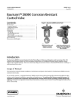
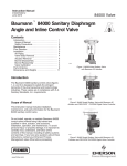
1
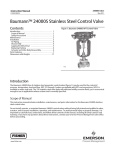
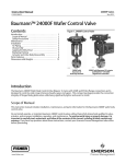
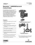
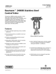
Instruction Manual 24003 Valve D103357X012 January 2014 Baumann™ 24003 3-Way Control Valve Contents Figure 1. Baumann 24003 3-Way Valve Introduction . . . . . . . . . . . . . . . . . . . . . . . . . . . . . . . . . . . 1 Scope of Manual . . . . . . . . . . . . . . . . . . . . . . . . . . . . . 1 Safety Precautions . . . . . . . . . . . . . . . . . . . . . . . . . . . 2 Educational Services . . . . . . . . . . . . . . . . . . . . . . . . . 3 Maintenance . . . . . . . . . . . . . . . . . . . . . . . . . . . . . . . . . 3 Installation . . . . . . . . . . . . . . . . . . . . . . . . . . . . . . . . . . 4 Air Piping . . . . . . . . . . . . . . . . . . . . . . . . . . . . . . . . . . . 4 Disassembly . . . . . . . . . . . . . . . . . . . . . . . . . . . . . . . . 4 Lapping the Valve Seat . . . . . . . . . . . . . . . . . . . . . . . 5 Replacing Packing . . . . . . . . . . . . . . . . . . . . . . . . . . . 5 Reassembly . . . . . . . . . . . . . . . . . . . . . . . . . . . . . . . . . 6 Parts Ordering . . . . . . . . . . . . . . . . . . . . . . . . . . . . . . . . 6 Special ENVIRO-SEAL™ Packing Note . . . . . . . . . . . . . 8 Dimensions and Weights . . . . . . . . . . . . . . . . . . . . . . . 9 Mixing and Diverting Applications . . . . . . . . . . . . . . 10 W9765 W9764 Stainless Steel 3-Way Valve with Baumann 32 Actuator Bronze 3-Way Valve with Baumann 54 Actuator and FIELDVUEt DVC2000 Digital Valve Controller Introduction The Baumann 24003 3-way control valve (figure 1) is ideally suited for control of flow and temperature where mixing or diverting service is required. Scope of Manual This instruction manual includes installation, maintenance, and parts information for the Baumann 24003 3-way control valve. Do not install, operate, or maintain Baumann 24003 3-way control valves without being fully trained and qualified in valve, actuator, and accessory installation, operation, and maintenance. To avoid personal injury or property damage, it is important to carefully read, understand, and follow all the contents of this manual, including all safety cautions and warnings. If you have any questions about these instructions, contact your Emerson Process Management sales office before proceeding. www.Fisher.com 24003 Valve January 2014 Instruction Manual D103357X012 WARNING Always wear protective gloves, clothing and eyewear when performing any installation operations to avoid personal injury. Personal injury or property damage caused by sudden release of pressure or bursting of pressure retaining parts may result if service conditions exceed those for which the product was intended. To avoid injury or damage, provide a relief valve for over pressure protection as required by government or accepted industry codes and good engineering practices. Check with your process or safety engineer for any additional measures that must be taken to protect against process media. If installing into an existing application, also refer to the WARNING at the beginning of the Maintenance section in this instruction manual. CAUTION This valve is intended for a specific range of pressures, temperatures and other application specifications. Applying different pressures and temperatures to the valve could result in parts damage, malfunction of the control valve or loss of control of the process. Do not expose this product to service conditions or variables other than those for which the product was intended. If you are not sure what these conditions are you should contact your Emerson Process Management sales office for more complete specifications. Provide the product serial numbers (shown on the nameplate) and all other pertinent information. WARNING If you move or work on an actuator installed on a valve with loading pressure applied, keep your hands and tools away from the stem travel path to avoid personal injury. Be especially careful when removing the stem connector to release all loading on the actuator stem whether it be from air pressure on the diaphragm or compression in the actuator springs. Likewise take similar care when adjusting or removing any optional travel stop. Refer to the relevant actuator Maintenance Instructions. If hoisting the valve, take care to prevent people from being injured in case the hoist or rigging slips. Be sure to use adequate sized hoists and chains or slings to handle the valve. WARNING Personal injury could result from packing leakage. Valve packing is tightened before shipment; however, the packing might require some readjustment to meet specific service conditions. 2 Instruction Manual D103357X012 24003 Valve January 2014 Educational Services For information on available courses for the Baumann 24003 valve, as well as a variety of other products, contact: Emerson Process Management Educational Services - Registration P.O. Box 190 Marshalltown, IA 50158-2823 Phone: 800-338-8158 or 641-754-3771 FAX: 641-754-3431 e-mail: [email protected] Maintenance WARNING Avoid personal injury and property damage from sudden release of process pressure or bursting of parts. Before performing any maintenance operations: D Do not remove the actuator from the valve while the valve is still pressurized. D Always wear protective gloves, clothing, and eyewear when performing any maintenance operations. D Disconnect any operating lines providing air pressure, electric power, or a control signal to the actuator. Be sure the actuator cannot suddenly open or close the valve. D Use bypass valves or completely shut off the process to isolate the valve from process pressure. Relieve process pressure on both sides of the valve. Drain the process media from both sides of the valve. D Depending on the actuator construction, it will be necessary to manage the pneumatic actuator spring pre-compression. It is essential to refer to the relevant actuator instructions in this manual to perform safe removal of the actuator from the valve. D Use lock-out procedures to be sure the above measures stay in effect while you work on the equipment. D The valve packing box may contain process fluids that are pressurized, even when the valve has been removed from the pipeline. Process fluids may spray out under pressure when removing the packing hardware or packing rings, or when loosening the packing box pipe plug. D Check with your process or safety engineer for any additional measures that must be taken to protect against process media. Note Whenever a gasket seal is disturbed by removing or shifting gasketed parts, install a new gasket during reassembly. This provides a good gasket seal because the used gasket may not seal properly. WARNING Avoid personal injury or property damage by thoroughly cleaning the line of all dirt, welding chips, scale, oil or grease, and other foreign material. Failure to do so could result in parts damage, malfunction of the control valve or loss of control of the process. 3 24003 Valve January 2014 Instruction Manual D103357X012 Installation 1. Before installing the valve in the pipeline, thoroughly clean the line of all dirt, welding chips, scale, oil or grease, and other foreign material. 2. Install the valve so the controlled fluid will flow through the valve body in the direction indicated for either mixing or diverting service (see table 1). 3. A three-valve bypass must be used to permit removal of the control valve from the line without shutting down the system. 4. In case of a heat-insulated installation, insulate the valve body only, not the bonnet. WARNING To avoid personal injury or property damage, do not attempt to do any work on a valve while the system is in operation. The valve must be isolated 100% from the active system and the isolated line voided of pressure and/or hazardous fluids. Air Piping 1. For an air-to-extend actuator (air-to-close Port L), connect the actuating air pressure line to the 1/4 NPT opening in the upper diaphragm case. For an air-to-retract actuator (air-to-open Port L) connect the actuating air pressure line to the 1/4 NPT in the lower diaphragm case. 2. Use 6.4 mm (1/4 inch) O.D. tubing or equivalent for all air lines. If air line exceeds 8 m (25 ft) in length, 9.5 mm (3/8 inch) tubing is preferred. Air lines must not leak. Air pressure not to exceed 2.5 bar (35 psig). CAUTION D When assembling or disassembling the valve, do not turn the valve stem while the plug is touching the valve seat. This can damage the valve's seating surface very quickly. D When adjusting the valve stem, do not grip the stem directly with pliers or a wrench. This will damage the surface of the stem, and cause damage to the packing in the valve. Instead, counter-tighten the two locknuts (key 27) on the stem (key 5). This will allow you to turn the stem by turning the locknuts (key 27) with a wrench. Disassembly WARNING When placing the valve in a vise, clamp the flat end faces of the valve. Do not try to clamp the rounded sides of the valve. This will distort the shape of the casting, and damage the valve internals. 1. Mount the valve in a vise. 2. Remove the actuator, stem locknuts (key 27), travel indicator (key 58), and yoke drive nut (key 8). See the following instruction manual (Baumann Actuator Instructions, D103352X012). 4 Instruction Manual D103357X012 24003 Valve January 2014 3. Unscrew the bonnet (key 3) by turning in a counterclockwise direction from the valve body (key 1). Lift the bonnet up and off the plug and stem assembly (key 4). 4. Unscrew the lower seat ring retainer (key 5) from the valve body (key 1) and remove the plug and stem assembly (key 4) (see figure 2). Wipe the parts with a clean soft cloth and examine for signs of wear. Lapping the Valve Seat If valve seat leakage becomes excessive, it may be necessary to lap the valve seat. Lapping is the process of mating the valve plug to the seat ring, with an abrasive to produce a close fit. When valve seat leakage becomes excessive, lapping becomes necessary. The plug and seat ring seating surfaces should be free of large scratches or dents and the contact surface of the seats should be as narrow as possible. 1. Use a good quality lapping compound with a mixture that contains 280 to 600 grit. Apply at several spots around the plug seating surface. 2. Replace the plug and stem assembly (key 4) through the bottom of the valve body (key 1) and screw in the lower seat ring retainer (key 5). 3. Place the bonnet (key 3) loosely into the valve body to serve as a guide during the lapping operation. 4. Rotate the plug and stem assembly (key 4), applying light pressure to the plug/seat mating surface. 5. Lap as little as possible. Excessive lapping will shoulder the seat ring, and will not improve the seating. Repeat for the second seating surface. 6. Clean the valve seats and plug thoroughly when the lapping is complete. Replacing Packing Refer to figure 2 and the standard and optional packing constructions (figures 3, 4, and 5) to determine the packing that has been preinstalled in your valve. 1. Mount the valve in a vise. 2. Remove actuator, stem locknuts (key 27), travel indicator (key 58), packing follower (key 7), and yoke drive nut (key 8) per actuator instructions D103352X012. 3. Unscrew the bonnet (key 3) by turning in a counterclockwise direction from the valve body (key 1). Lift the bonnet up and off the plug and stem assembly (key 4). Push the old packing out from the underside of the bonnet (key 3). 4. Standard Spring Loaded PTFE V-Ring Packing (figures 2 and 3): Carefully insert each piece in exact order shown in figure 3. Turn the packing follower (key 7) until it shoulders on the bonnet (key 3). This will compress the packing spring (key 9) to enable constant stem sealing throughout packing life. 5. Molded Graphite Ribbon Packing (figure 4): Carefully insert each piece in exact order shown in figure 4. Hand tighten the packing follower (key 7). Use a wrench to increase tightness by turning the nut an additional 60 degrees. 6. ENVIRO-SEAL Packing (figure 5): Carefully insert each piece in exact order as shown in figure 5. Tighten the packing follower (key 7) until the Belleville springs are compressed. This will be signaled by a significant increase in resistance. Back off the follower 1/8 to 1/4 turn. A gap of approximately 1/16 inch between the packing follower and the bonnet will ensure packing is seated properly. CAUTION Overtightening the packing may prevent stem movement and valve operation and result in equipment damage or loss of control of the process. 5 Instruction Manual 24003 Valve D103357X012 January 2014 Reassembly 1. Place the plug and stem assembly (key 4) into the valve body (key 1) from the lower port and screw in the lower seat ring retainer (key 5). 2. Place the bonnet (key 3) over the stem and tighten in place. 3. Insert the packing kit by following steps 4, 5, or 6 of Replacing Packing shown previously. 4. Place the actuator yoke over the stem and bonnet. While tilting the actuator back to allow access to the top of the stem, place the yoke drive nut (key 8) over the stem. 5. Next, turn one locknut (key 27) onto the stem, turning it down as far as possible. Place the travel indicator (key 58) over the stem and then turn the second locknut (key 27) down against the travel indicator (key 58). Counter turn the locknuts to tighten securely. See the following instruction manual (Baumann Actuator Instructions, D103352X012) for bench range adjustment. CAUTION When assembling or disassembling the valve, do not turn the valve stem while the plug is in contact with either seat. This can damage the seating surface very quickly. Table 1. Application Port(1) Service Inlet Outlet Diverting C U and L Mixing U and L C 1. C = common port, U = upper port, L = lower port Parts Ordering When corresponding with your Emerson Process Management sales office about this equipment, always mention the valve serial number. When ordering replacement parts, also specify the key number, part name, and desired material using the following parts tables. WARNING Use only genuine Fisherr replacement parts. Components that are not supplied by Emerson Process Management should not, under any circumstances, be used in any Fisher valve, because they may void your warranty, might adversely affect the performance of the valve, and could cause personal injury and property damage. 6 Instruction Manual 24003 Valve D103357X012 January 2014 Figure 2. Baumann 24003 Valve Cross-Sectional Views U C C U O-RING USED IN STAINLESS STEEL VALVE ASSEMBLY ONLY L E1281 L NPS 1-1/2 and 2 NPS 1/2 and 1 Table 2. Baumann 24003 Common Parts(1) VALVE SIZE KEY NO. QTY 1 1 2* DESCRIPTION DN 15 (NPS 1/2) Bronze 2 SST DN 25 (NPS 1) Bronze DN 40 (NPS 1-1/2) SST Bronze SST DN 50 (NPS 2) Bronze SST Valve Body --- --- --- --- Seat Ring, Cv = 1.0 B1790450-01 B1790450-01 --- --- Seat Ring, Cv = 2.0 B1790450-01 B1790450-01 --- --- Seat Ring, Cv = 4.0 B1790552-01 B1790552-01 --- --- Seat Ring, Cv = 10 --- B1790630-01 --- --- Seat Ring, Cv = 20 --- --- B1790830-01 --- Seat Ring, Cv = 40 --- --- --- C1790930-01 2B* 2 O-Ring 3 1 Bonnet --- --- --- --- Plug & Stem Assy, Cv = 1.0 B3880400 B3880400 --- --- Plug & Stem Assy, Cv = 2.0 B3880401 B3880401 --- --- Plug & Stem Assy, Cv = 4.0 B3880500 B3880500 --- --- Plug & Stem Assy, Cv = 10 --- B3880600 --- --- Plug & Stem Assy, Cv = 20 --- --- C3880900-02 --- Plug & Stem Assy, Cv = 40 --- --- --- C3880900-01 --- --- --- --- 4* 1 --- 04907134 --- 04907134 --- 5 1 Lower Seat Ring Retainer 6* 1 Packing Kit 7 1 Packing Follower 24490-1 8 1 Drive Nut, Actuator Yoke 011757-003-153 27 2 Stem Locknut 971514-002-250 58 1 Travel Indicator 24299 04907144 --- 04907150 See Packing Details on page 8 1. Serial number of valve is required. 7 Instruction Manual 24003 Valve D103357X012 January 2014 Figure 3. Spring-Loaded PTFE V-Ring Packing Kit P/N 24494T001 Figure 5. ENVIRO-SEAL Packing Kit P/N 24490T001 E1248 E1240 Table 3. Spring-Loaded PTFE V-Ring Packing Kit P/N 24494T001 Key No. Description Material 9* Spring ASTM A313 S30200 14 Packing Set PTFE / carbon-filled PTFE 16 Washer ASTM A240 S31600 20 Spacer J-2000 (filled PTFE) Table 5. ENVIRO-SEAL Packing Kit P/N 24490T001 Key No. Description Material 13 Bushing, qty 2 Carbon Graphite 14 Packing Set PTFE / carbon-filled PTFE 17 Belleville Spring ASTM B637 N07718 18 Bushing PEEK 19 Washer, qty 2 Modified PTFE Figure 4. Molded Graphite (Flexible Graphite) Pack ing Kit P/N 24492T001 Special ENVIRO-SEAL Packing Note The ENVIRO-SEAL PTFE packing system is suitable for 100 ppm environmental applications on services up to 51.7 bar (750 psig) and process temperatures ranging from -46 to 232_C (-50 to 450_F). For non-environmental applications, this packing system offers excellent performance at the same temperature range up to the maximum valve working pressure. E1241 Table 4. Molded Graphite (Flexible Graphite) Packing Kit P/N 24492T001 Key No. Description Material 13 Bushing, qty 2 Carbon - Graphite 14 Packing Rings, qty 4 Graphite 8 Temperature limits apply to packing arrangements only. Complete valve assembly temperature limits may differ. Refer to appropriate pressure/ temperature ratings. Reference Fisher Packing Selection Guidelines for Sliding-Stem Valves, bulletin 59.1:062, D101986X012. Instruction Manual 24003 Valve D103357X012 January 2014 Figure 6. Dimensional Drawings 333 (413.1) 279 216 (48.5) 127 (411.0) (5.0) 141 (5.5) 60 (2.4) 276 (10.9) 229 (9.0) C1 3/4 INCH SQUARE 271 (10.7) BAUMANN 54 ACTUATOR w/ FIELDVUE DVC2000 DIGITAL VALVE CONTROLLER U C B 229 (9.0) BAUMANN 70 ACTUATOR w/ FIELDVUE DVC6010 DIGITAL VALVE CONTROLLER L A 24003 3-WAY WITH BAUMANN 32 ACTUATOR AND 3660/3661 POSITIONER 279 (411.0) 160 160 (46.3) (46.3) 279 (411.0) 163 (6.4) BAUMANN 32 ATC/FAIL OPEN ACTUATOR WITH HANDWHEEL 94 (3.7) 152 (46.0) 130 (5.1) MAX 152 (46.0) 71 (2.8) MAX 31 (1.24) BAUMANN 32 ATO/FAIL CLOSED ACTUATOR WITH HANDWHEEL BAUMANN 32 ACTUATOR WITH ADJUSTABLE OPEN/CLOSE DUAL TRAVEL STOPS BAUMANN 54 ATC / FAIL OPEN ACTUATOR WITH HANDWHEEL BAUMANN 54 ATO/FAIL CLOSED ACTUATOR w/ HANDWHEEL mm (inch) E1285 NOTE: ACTUATOR REMOVAL REQUIRES 115 mm (4.5 INCHES) VERTICAL CLEARANCE. Table 6. Valve Dimensions and Weights, NPT Valve Bodies Only VALVE BODY MATERIAL VALVE SIZE Bronze, NPT Stainless Steel, NPT TRAVEL WEIGHT DN NPS A B C1 A B C1 Inches lbs 15 1/2 4.875 2.75 2.75 4.8125 2.75 2.75 0.56 8 25 1 4.875 2.75 2.75 5.0 2.75 2.75 0.56 8 40 1-1/2 5.75 3.8125 3.3125 6.125 3.375 3.125 0.75 15 50 2 6.50 4.0 3.625 6.50 3.75 3.625 0.75 20 9 Instruction Manual 24003 Valve D103357X012 January 2014 Table 8. Application Port(1) Table 7. Actuator Weights WEIGHTS ACTUATOR TYPE kg lb 32 4.5 10 54 11.3 25 70 15.4 34 Service Inlet Outlet Diverting C U and L Mixing U and L C 1. C = Common port, U = Upper port, L = Lower port Figure 7. Mixing and Diverting Applications DIVERTING VALVE COOL WATER HEATING WATER C U TEMPERED WATER MIXING VALVE L HEAT EXCHANGER C U E1286 10 L RETURN Instruction Manual D103357X012 24003 Valve January 2014 11 24003 Valve January 2014 Instruction Manual D103357X012 Neither Emerson, Emerson Process Management, nor any of their affiliated entities assumes responsibility for the selection, use or maintenance of any product. Responsibility for proper selection, use, and maintenance of any product remains solely with the purchaser and end user. Baumann, Fisher, FIELDVUE, and ENVIRO-SEAL are marks owned by one of the companies in the Emerson Process Management business unit of Emerson Electric Co. Emerson Process Management, Emerson, and the Emerson logo are trademarks and service marks of Emerson Electric Co. All other marks are the property of their respective owners. The contents of this publication are presented for informational purposes only, and while every effort has been made to ensure their accuracy, they are not to be construed as warranties or guarantees, express or implied, regarding the products or services described herein or their use or applicability. All sales are governed by our terms and conditions, which are available upon request. We reserve the right to modify or improve the designs or specifications of such products at any time without notice. Emerson Process Management Marshalltown, Iowa 50158 USA Sorocaba, 18087 Brazil Chatham, Kent ME4 4QZ UK Dubai, United Arab Emirates Singapore 128461 Singapore www.Fisher.com 12 E 2009, 2014 Fisher Controls International LLC. All rights reserved.