1
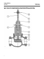
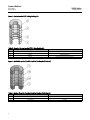
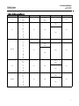
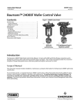
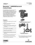
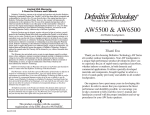
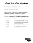
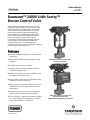
Product Bulletin 24000 Valve 52.1:24LS March 2013 D103327X012 Baumann™ 24000 Little Scotty™ Bronze Control Valve Baumann Little Scotty industrial control valves are intended for general utility service in pressure, flow, and temperature control applications. This control valve is positioned to take advantage of the trend toward industrial grade requirements spanning general utility to special applications. Little Scotty valves exhibit low hysteresis and deadband, good control characteristics, tight shutoff, rugged construction, high performance packing, and easy maintainability. These attributes translate into reduced maintenance costs, reduced process variability, and increased process availability, resulting in lower long-term operating costs. Features Compact and light weight design reduces installed piping costs High quality S31600 austenitic stainless steel trim materials S41600 stainless steel trim available Dual plug and stem guiding provides increased stability during plug travel Multiple trim capacity reductions available to meet changing process requirements Epoxy powder-coated actuator with stainless steel fasteners for corrosion resistance Multi-spring, field-reversible actuator with reduced deadband, permits direct operation from remote signal devices Actuator and yoke can be removed from the valve assembly while maintaining packing integrity W9752 Fisherr FIELDVUEt digital valve controller available for remote calibration and diagnostics in facilities utilizing the PlantWebt architecture www.Fisher.com 24000 Little Scotty Control Valve with Baumann 32 Actuator W9753 24000 Little Scotty Control Valve with Baumann 32 Actuator and FIELDVUE DVC2000 Digital Valve Controller Product Bulletin 52.1:24LS March 2013 Figure 1. Baumann Little Scotty Valve Body Subassembly with Standard PTFE Spring-Loaded Packing E1259 2 24000 Valve D103327X012 Product Bulletin 24000 Valve 52.1:24LS March 2013 D103327X012 Table 1. Materials of Construction Key No. Description 1 Valve Body 2 Seat Ring Plug (Metal Seat) Cv < 2.5 4 Plug (Metal Seat) Cv > 4.0 Material ASTM B62 Grade C83600 Standard ASTM A276 S31600/ S31603 Dual Certified Optional ASTM A582 S41600 Condition T Standard ASME SA479 S21800 Optional ASTM A582 S41600 Condition T Standard ASTM A276 S31600/ S31603 Optional ASTM A582 S41600 Condition T Plug (Soft Seat) ASTM A276 S31600/ S31603 with PTFE (Polytetrafluoroethylene) insert 5 Stem ASTM A276 S31600 8 Bonnet ASTM B148 Alloy C95500 9 Drive Nut (Yoke) S30400 10 Packing Follower ASTM A276 S31600/ S31603 Dual Certified 14 Packing 27 Standard V-Ring, see figure 2 Optional Molded Graphite, see figure 3 Locknuts 49 Body Gasket 58 Stainless Steel (18-8 SST) Standard Annealed Soft Copper Optional Graphite Grade GHR with S31600 Insert Travel Indicator ASME SA240 S30400 Table 2. Cv Values at 100% Plug Opening (Kv = 0.86 x Cv) VALVE SIZE ORIFICE DIAMETER PLUG TRAVEL NPS inch PLUG SERIES 102 577 548 / 588 677 inch Cv Cv Cv Cv 648 / 688 Cv --- 0.2, 0.5 1.0 --- 0.5 1.0 1.0, 1.5, 2.5 1.5, 2.5 0.1, 0.2, 0.5 1.0, 2.5 1.5 2.5 1/2 3/4 1 0.25 0.50 0.02, 0.05 0.10, 0.20 0.375 0.50 --- 1/2 0.8125 0.50 --- 4, 6 4, 6 5 4, 6 3/4 0.8125 0.50 --- 4, 7.5 4, 8 5 4, 8 0.8125 0.50 --- 4, 8.5 4, 9 5 4, 9 1.0625 0.50 --- 13 13 --- 13 1.25 0.75 --- 20 10, 20 20 10, 20 1.5 0.75 --- 10, 17, 28 10, 17, 28 10, 17 10, 17, 28 1.5 0.75 --- 10, 17, 28 10, 17, 28 10, 17 10, 17, 28 2.0 0.75 --- 30 30, 50 30, 50 30, 50 1 1-1/2 2 3 Product Bulletin 24000 Valve 52.1:24LS March 2013 D103327X012 Figure 2. Spring-Loaded PTFE V-Ring Packing Kit E1240 Table 3. Standard Spring-Loaded PTFE V-Ring Packing Kit Key No. Description Material 6 Spring ASTM A313 S30200 14 Packing Set PTFE (Polytetrafluoroethylene) / PTFE, 25% carbon filled 16 Washer ASME SA240 S31600 20 Spacer J-2000 (filled-Polytetrafluoroethylene) Figure 3. Molded Graphite (Flexible Graphite) Packing Kit (Optional) E1241 Table 4. Molded Graphite (Flexible Graphite) Packing Kit (Optional) Key No. Description Material 13 Bushings Carbon - Graphite 14A Packing Rings Graphite 14B Packing Ring Graphite 4 Product Bulletin 24000 Valve 52.1:24LS March 2013 D103327X012 Table 5. ISA Sizing Coefficients Series Cv Rating 102 0.2 0.04 0.09 0.17 577 1 1.5 2.5 4 6 7.5 8.5 10 13 17 20 28 30 548/588 677 648/688 0.2 0.5 1 1.5 2.5 4 6 8 9 10 13 17 20 28 30 50 0.1 0.2 0.5 1 2.5 5 10 17 30 50 0.5 1 1.5 2.5 4 6 8 9 10 13 20 FL Fd XT KC 0.95 0.06 0.09 0.013 0.18 0.76 0.86 0.40 0.33 0.42 0.9 1.46 0.73 0.68 0.98 0.28 0.81 0.94 0.68 0.73 0.4 0.33 0.46 0.9 0.46 0.08 0.12 0.19 0.27 0.9 0.46 0.73 0.68 0.4 0.33 0.42 0.9 0.46 0.73 0.68 5 Product Bulletin 24000 Valve 52.1:24LS March 2013 D103327X012 Table 6. Technical Specifications VALVE TYPE EN ASME NOMINAL SIZE DN 15, 20, 25, 40, & 50 NPS 1/2, 3/4, 1, 1-1/2, & 2 END CONNECTIONS Screwed NPT PRESSURE RATING 400 psi @ 150_F / 250 psi @ 400_F (ASME B16.15 CL250) SEAT PLUG SEALING Metal to metal or PTFE soft seat Equal Percentage or Linear CHARACTERISTIC TEMPERATURE LIMITS -29 to 204_C -20 to 400_F Table 7. Actuator Specifications TYPE 32, 54, 70 Multi-Spring Diaphragm (Single Acting) DIAPHRAGM AREA 210, 350, 450 cm2 / 32, 54, 70 in2 AIR FAILURE 32 and 54 Fails Open or Closed (Field Reversible) / 70 Fails Closed ONLY TRAVEL(1) 12.7 or 19.1 mm / 0.50 or 0.75 inches AMBIENT TEMPERATURE RANGE -29_C to 71_C / -20_F to 160_F MAXIMUM AIR PRESSURE 2.4 barg / 35 psig DIAPHRAGM MATERIAL(2) NBR (Nitrile) / TPES (Polyester Thermoplastic) SPRING CASES Steel, Powder Epoxy-Coated with Stainless Steel Fasteners YOKE Ductile Iron, Powder Epoxy-Coated 1. Dual travel stops are available on Baumann 32 and 54 actuators. These are not field reversible. 2. Optional reinforced VMQ (Silicone) diaphragm with FKM (Fluorocarbon) O-ring actuator stem seal for high temperature conditions (-29_C to 121_C / -20_F to 250_F) is available with Baumann 32 and 54 actuators ONLY. 6 Product Bulletin 24000 Valve 52.1:24LS March 2013 D103327X012 Figure 4. Baumann 24000 Pressure-Temperature Ratings 400 psi @ -20_F 400 psi @ 150_F 250 psi @ 400_F E1260 OPERATING TEMPERATURE (_F) 27.6 bar @ -28.8_C 27.6 bar @ 65.5_C 17.2 bar @ 204_C OPERATING TEMPERATURE (_C) E1261 7 Product Bulletin 24000 Valve 52.1:24LS March 2013 D103327X012 Table 8. Allowable Pressure Drops (bar) AIR-TO-OPEN ACTION ORIFICE DIA. (mm) PLUG TRAVEL (mm) ACT TYPE BENCH RANGE (barg) 6.3 12.7 32 9.5 12.7 32 32 0.3-1.0 32 0.5-1.0 54 0.3-1.0 54 20.6 27.0 31.8 38.1 50.8 12.7 12.7 19.1 19.1 19.1 0.2-1.0 barg SIGNAL TO ACTUATOR AIR-TO-CLOSE ACTION WITH POSITIONER 1.38 barg AIR SUPPLY Max CL Max CL IV VI Shutoff Shutoff Press. Press. BENCH RANGE (barg) 0.2-1.0 barg SIGNAL TO ACTUATOR Max CL IV Shutoff Press. Max CL VI Shutoff Press. WITH POSITIONER 1.38 barg AIR SUPPLY Max CL Max CL IV VI Shutoff Shutoff Press. Press. Max CL IV Shutoff Press. Max CL VI Shutoff Press. 0.3-1.0 27.58 27.58 --- --- 0.2-0.9 27.58 --- 27.58(1) --- 0.3-1.0 27.58 19.17 --- 27.58 0.2-0.9 27.58 19.17 27.58(1) 27.58(1) 7.79 --- 15.58 9.10 0.2-0.9 7.7 --- 21.09 20.75 15.58 9.10 23.37 16.89 0.2-0.7 19.51 12.96 27.58 27.58 5.92 --- 17.71 11.16 0.2-0.9 11.79 5.30 27.58(1) 27.58 0.5-1.0 23.64 17.09 27.58 27.58 0.2-0.7 27.58 23.02 27.58(1) 27.58(1) 54 0.6-1.0 27.58 27.58 27.58(1) 27.58(1) --- --- --- --- --- 32 0.3-1.0 4.68 --- 9.44 4.27 0.2-0.9 4.68 --- 16.47 11.37 32 0.5-1.0 9.44 4.27 14.13 8.96 0.2-0.7 11.79 6.61 23.58 18.40 54 0.3-1.0 3.58 --- 10.68 5.58 0.2-0.9 7.17 1.99 25.02 19.85 54 0.5-1.0 14.27 9.10 21.44 16.27 0.2-0.7 17.85 12.68 27.58(1) 27.58 54 0.6-1.0 21.44 16.27 27.58 23.44 --- --- --- --- --- 32 0.3-1.0 3.44 --- 6.96 2.48 0.2-0.9 3.44 --- 12.13 7.65 32 --- --- --- --- --- 0.2-0.7 8.68 4.20 17.30 12.89 54 0.3-1.0 5.24 --- 10.48 6.06 0.2-0.9 5.24 --- 18.34 13.92 54 0.5-1.0 10.48 6.06 15.72 11.60 0.2-0.7 13.10 8.68 26.26 21.78 54 0.7-1.0 18.34 16.92 23.64 19.17 --- --- --- --- --- 70 0.7-1.0 24.95 20.47 27.58 27.58 --- --- --- --- --- 32 0.3-1.0 2.41 --- 4.89 --- 0.2-0.9 2.41 --- 8.54 4.75 8.48 32 --- --- --- --- --- 0.2-0.7 6.13 2.34 12.20 54 0.3-1.0 3.72 --- 7.37 3.65 0.2-0.9 3.72 --- 12.96 9.17 54 0.5-0.9 7.37 3.65 11.10 7.30 0.2-0.7 9.23 5.51 18.54 14.75 54 0.7-1.0 12.96 9.17 16.68 12.89 --- --- --- --- --- 70 0.7-1.0 17.65 13.85 22.68 18.89 --- --- --- --- --- 70 0.8-1.2 --- --- 27.58 23.92 --- --- --- --- --- 32 0.3-1.0 1.37 --- 2.82 --- 0.2-0.9 1.37 --- 4.89 1.99 32 --- --- --- --- --- 0.2-0.7 3.51 --- 7.03 4.13 54 0.3-1.0 2.13 --- 4.27 1.37 0.2-0.9 2.13 --- 7.44 4.55 54 0.5-0.9 4.27 1.37 6.34 3.51 0.2-0.7 5.30 2.41 10.61 7.72 54 0.7-1.0 7.44 4.55 9.58 6.68 --- --- --- --- --- 70 0.7-1.0 10.13 7.23 13.03 10.13 --- --- --- --- --- 70 0.8-1.2 --- --- 15.85 13.03 --- --- --- --- --- 1. The maximum shutoff pressure when using Flexible Graphite packing is defined by: nP = Table Value - [5337/(Port Diameter)2]. These table values should not be modified by this formula and the maximum nP of 27.6 bar should be used for Flexible Graphite packing. 8 Product Bulletin 24000 Valve 52.1:24LS March 2013 D103327X012 Table 9. Allowable Pressure Drops (psi) AIR-TO-OPEN ACTION 3-15 psig SIGNAL TO ACTUATOR Max CL Max CL IV VI Shutoff Shutoff Press. Press. AIR-TO-CLOSE ACTION WITH POSITIONER 20 psig AIR SUPPLY Max CL Max CL IV VI Shutoff Shutoff Press. Press. 3-15 psig SIGNAL TO ACTUATOR Max CL Max CL IV VI Shutoff Shutoff Press. Press. WITH POSITIONER 20 psig AIR SUPPLY Max CL Max CL IV VI Shutoff Shutoff Press. Press. ORIFICE DIA. (in) PLUG TRAVEL (in) ACT TYPE BENCH RANGE (psig) 0.25 0.50 32 5-15 400 --- 400 --- 3-13 400 --- 400(1) --- 0.375 0.50 32 5-15 400 278 --- 400 3-13 400 278 400(1) 400(1) 32 5-15 113 --- 226 132 3-13 113 --- 306 301 32 7-15 226 132 339 245 3-10 283 188 400 400 54 4-15 86 --- 257 162 3-13 171 77 400(1) 400 54 7-15 343 248 400 400 3-10 400 334 400(1) 400(1) 54 9-15 400 400 400(1) 400(1) --- --- --- --- --- 32 5-15 68 --- 137 62 3-13 68 --- 239 165 32 7-15 137 62 205 130 3-10 171 96 342 267 54 4-15 52 --- 155 81 3-13 104 29 363 288 54 7-15 207 132 311 236 3-10 259 184 400(1) 400 54 9-15 311 236 400 340 --- --- --- --- --- 32 5-15 50 --- 101 36 3-13 50 --- 176 111 0.8125 1.0625 1.25 1.5 2.0 0.50 0.50 0.75 0.75 0.75 BENCH RANGE (psig) 32 --- --- --- --- --- 3-10 126 61 251 187 54 5-15 76 --- 152 88 3-13 76 --- 266 202 54 7-13 152 88 228 164 3-10 190 126 381 316 54 10-14 266 202 343 278 --- --- --- --- --- 70 10-15 362 297 400 400 --- --- --- --- --- 32 5-15 35 --- 71 --- 3-13 35 --- 124 69 32 --- --- --- --- --- 3-10 89 34 177 123 54 5-15 54 --- 107 53 3-13 54 --- 188 133 54 7-13 107 53 161 106 3-10 134 80 269 214 54 10-14 188 133 242 187 --- --- --- --- --- 70 10-15 256 201 329 274 --- --- --- --- --- 70 12-18 --- --- 400 347 --- --- --- --- --- 32 5-15 20 --- 41 --- 3-13 20 --- 71 29 60 32 --- --- --- --- --- 3-10 51 --- 102 54 5-15 31 --- 62 20 3-13 31 --- 108 66 54 7-13 62 20 92 51 3-10 77 35 154 112 54 10-14 108 66 139 97 --- --- --- --- --- 70 10-15 147 105 189 147 --- --- --- --- --- 70 12-18 --- --- 230 189 --- --- --- --- --- 1. The maximum shutoff pressure when using Flexible Graphite packing is defined by: nP = Table Value - [120/(Port Diameter)2]. These table values should not be modified by this formula and the maximum nP of 400 psi should be used for Flexible Graphite packing. 9 Product Bulletin 24000 Valve 52.1:24LS March 2013 D103327X012 Figure 5. Dimensional Drawings 333 (413.1) 216 (48.5) 279 (411.0) 60 (2.4) 127 (5.0) 141 (5.5) 229 (9.0) 271 (10.7) 276 (10.9) 3660/3661 POSITIONER (OPTIONAL) B 229 (9.0) E BAUMANN 54 WITH FIELDVUE DVC2000 DIGITAL VALVE CONTROLLER DVC6010 BAUMANN 70 WITH FIELDVUE DVC6010 DIGITAL VALVE CONTROLLER A 24000 WITH BAUMANN 32 ACTUATOR AND FISHER 3660/3661 POSITIONER 160 (46.3) 160 (46.3) 152 (46.0) 94 (3.7) MAX 163 (6.4) MAX 130 (5.1) MAX 71 (2.8) MAX 276 (10.9) BAUMANN 32 ATO/FAIL CLOSED ACTUATOR WITH HANDWHEEL BAUMANN 32 ATC/ FAIL OPEN ACTUATOR WITH HANDWHEEL BAUMANN 54 ATO/FAIL CLOSED ACTUATOR WITH HANDWHEEL BAUMANN 54 ATC / FAIL OPEN ACTUATOR WITH HANDWHEEL 125 (4.9) 31 (1.24) 284 (11.2) E1262 BAUMANN 32 ACTUATOR WITH ADJUSTABLE OPEN/CLOSE DUAL TRAVEL STOPS Note: Actuator removal requires 115 mm (4.5 inches) vertical clearance. 10 BAUMANN NV ELECTRIC ACTUATOR mm (inch) Product Bulletin 24000 Valve 52.1:24LS March 2013 D103327X012 Table 10. Dimensions VALVE SIZE A VALVE BODY B BONNET E DN NPS mm inch mm inch mm inch 15 1/2 89 3.5 78 3.1 27 1.06 20 3/4 89 3.5 78 3.1 27 1.06 25 1 109 4.3 83 3.3 33 1.3 40 1-1/2 137 5.4 99 3.9 46 1.8 50 2 168 6.6 104 4.1 58 2.3 Table 11. Valve Assembly Weights VALVE SIZE Table 13. Pneumatic Actuators Actuator Type WEIGHT DN NPS kg lb 32 15 1/2 1.6 3.5 54 20 3/4 1.6 3.5 70 25 1 2.3 5.0 40 1-1/2 4.9 10.9 50 2 8.9 19.7 Table 14. Electric Actuators(1) Table 12. Actuator Weights WEIGHTS ACTUATOR TYPE kg lb 32 4.5 10 54 11.3 25 70 15.4 34 MV1020 10 22 VA1020 14 30 NV24-MFT (non spring return) 1.5 3.3 NVF24-MFT or NVF24-MFT-E (spring return) 1.8 4 Actuator Type Travel MV1020 32 VA1020 54 NV(2) 70 NVF(3) 54 NVFE(4) 70 1. Refer to bulletin 52.1:NVACT, D103326X012 for details. 2. NV24-MFT = Non Spring Return 3. NVF24-MFT = Spring return - fail open. 4. NVF24-MFT-E = Spring return - fail closed. Table 15. Model Numbering System 24 Actuator Type(1) Valve Body Series Plug Series Characteristic Seat Leakage 102 Linear / Metal Seat IV 548 Equal % / Metal Seat (S41600) IV 577 Equal % / PTFE Seat VI 588 Equal % / Metal Seat (S31600) IV 677 Linear / PTFE Seat VI 648 Linear / Metal Seat (S41600) IV 688 Linear / Metal Seat IV 1. Choose from tables 13 and 14. 11 Product Bulletin 52.1:24LS March 2013 24000 Valve D103327X012 Neither Emerson, Emerson Process Management, nor any of their affiliated entities assumes responsibility for the selection, use or maintenance of any product. Responsibility for proper selection, use, and maintenance of any product remains solely with the purchaser and end user. Baumann, Little Scotty, Fisher, FIELDVUE, and PlantWeb are marks owned by one of the companies in the Emerson Process Management business unit of Emerson Electric Co. Emerson Process Management, Emerson, and the Emerson logo are trademarks and service marks of Emerson Electric Co. All other marks are the property of their respective owners. The contents of this publication are presented for informational purposes only, and while every effort has been made to ensure their accuracy, they are not to be construed as warranties or guarantees, express or implied, regarding the products or services described herein or their use or applicability. All sales are governed by our terms and conditions, which are available upon request. We reserve the right to modify or improve the designs or specifications of such products at any time without notice. Emerson Process Management Marshalltown, Iowa 50158 USA Sorocaba, 18087 Brazil Chatham, Kent ME4 4QZ UK Dubai, United Arab Emirates Singapore 128461 Singapore www.Fisher.com E 122009, 2013 Fisher Controls International LLC. All rights reserved.