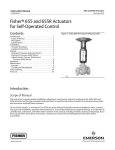
1
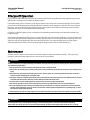
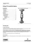
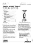
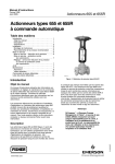
Instruction Manual 644 and 645 Pump Governors D100302X012 February 2014 Fisherr 644 and 645 Differential Pressure Pump Governors Contents Introduction . . . . . . . . . . . . . . . . . . . . . . . . . . . . . . . . . 1 Scope of Manual . . . . . . . . . . . . . . . . . . . . . . . . . . . . . 1 Description . . . . . . . . . . . . . . . . . . . . . . . . . . . . . . . . . 1 Specifications . . . . . . . . . . . . . . . . . . . . . . . . . . . . . . . 2 Educational Services . . . . . . . . . . . . . . . . . . . . . . . . . 3 Installation . . . . . . . . . . . . . . . . . . . . . . . . . . . . . . . . . . 3 Direct-Acting Actuators . . . . . . . . . . . . . . . . . . . . . . . 4 Reverse-Acting Actuators . . . . . . . . . . . . . . . . . . . . . 5 Overpressure . . . . . . . . . . . . . . . . . . . . . . . . . . . . . . . . . 6 Startup . . . . . . . . . . . . . . . . . . . . . . . . . . . . . . . . . . . . . . 6 Adjustment . . . . . . . . . . . . . . . . . . . . . . . . . . . . . . . . . 6 Principle of Operation . . . . . . . . . . . . . . . . . . . . . . . . . 7 Maintenance . . . . . . . . . . . . . . . . . . . . . . . . . . . . . . . . . 7 Disassembly . . . . . . . . . . . . . . . . . . . . . . . . . . . . . . . . 8 Reassembly . . . . . . . . . . . . . . . . . . . . . . . . . . . . . . . . . 8 Parts Ordering . . . . . . . . . . . . . . . . . . . . . . . . . . . . . . . 10 Parts List . . . . . . . . . . . . . . . . . . . . . . . . . . . . . . . . . . . 10 Figure 1. Fisher 644 Actuator Mounted on a Typical easy-e™ Valve W2265-1 Introduction Scope of Manual This instruction manual provides information on installation, adjustment, maintenance, and parts ordering for the Fisher 644 and 645 differential pressure pump governors. Refer to separate instruction manuals for information about the valve and other accessories used with these governors. Do not install, operate, or maintain 644 or 645 governors without being fully trained and qualified in valve, actuator, and accessory installation, operation, and maintenance. To avoid personal injury or property damage, it is important to carefully read, understand, and follow all the contents of this manual, including all safety cautions and warnings. If you have any questions about these instructions, contact your Emerson Process Management sales office before proceeding. Description 644 and 645 actuators are used in combination with any of several sliding-stem valves to automatically control steam-driven boiler feedwater pumps (reciprocating or turbine). The 644 or 645 actuator (see figures 1 and 2), when used in combination with one of several push-down-to-close sliding-stem valves, forms a pump governor. 644 and 645 actuators may also be combined with push-down-to-open valves to be used as relief governors. Relief governors are used to divert excess pump discharge back to the suction side of the pump. www.Fisher.com Instruction Manual 644 and 645 Pump Governors D100302X012 February 2014 Table 1. Specifications Actuator Sizes Maximum nP Across Diaphragm See table 2 13.8 bar (200 psi) Actuator Travel Effective Diaphragm Area Chloroprene Diaphragm: 11 mm (0.4375 inch) maximum Stainless Steel Diaphragm: 3 mm (0.125 inch) maximum 644: Size 1: 146 cm2 (8.9 inch2) Size 2: 243 cm2 (14.8 inch2) Size 3: 364 cm2 (22.2 inch2) 645: 338 cm2 (20.6 inch2) Operating Principle Material Temperature Capabilities J Direct-acting with push-down-to-close valve J Reverse-acting with push-down-to-open valve 644: Chloroprene Diaphragm:-40 to 82_C (-40 to 180_F) Stainless Steel Diaphragm: Cast-iron casing: -40 to 232_C (-40 to 450_F); Steel Differential Pressure Ranges See table 2 casing: -40 to +399_C (-40 to 750_F) 645: -37 to 82_C (-35_ to 180_F) Maximum Casing Pressure Casing Pressure Connections 644 Actuator: Cast-Iron Casing: 20.7 bar (300 psig) Steel Casing: 41.4 bar (600 psig) 645 Actuator: Cast-Iron Casing: 34.5 bar (500 psig) Steel Casing: 69.0 bar (1000 psig) 1/4 NPT internal Spring Ranges and Sensitivity See table 2 Specifications Specifications for the 644 and 645 pump governors are shown in table 1. Information for a specific pump governor is also found on the nameplate of that pump governor. Table 2. Spring Information ACTUATOR Size 3 Casing Size 2 Casing Size 1 Casing 644 645 2 DIFFERENTIAL PRESSURE RANGE SPRING RATE SENSITIVITY Bar Psi N/mm Lbf/in mm/N In/Psi 0.3-1.2 1.2-1.9 1.9-2.8 2.8-3.8 3.8-4.7 4.7-6.9 1.0-1.7 1.7-2.4 2.4-3.2 3.2-4.1 4.1-4.3 4.3-5.9 5.9-6.8 6.8-8.2 8.2-9.7 9.7-10.7 5-18 18-27 27-40 40-55 55-68 68-100 14-24 24-35 35-47 47-59 59-62 62-85 85-99 99-119 119-140 140-155 56 107 107 165 107 165 43 64 86 107 129 145 221 257 310 368 314 609 609 940 609 940 246 368 490 612 735 830 1260 1470 1770 2100 26.1 13.5 9.0 6.2 5.4 3.7 21.0 14.0 10.5 11.0 7.1 6.2 4.1 3.5 2.9 2.5 0.0707 0.0365 0.0244 0.0168 0.0146 0.0101 0.057 0.038 0.0286 0.0299 0.0191 0.0169 0.0111 0.0095 0.0079 0.0067 SPRING PART NUMBER 1F945527032 1F945627032 1F945627032 1F945727042 1F945627032 1F945727042 1F714427112 1F176727032 1F176827092 1F176927092 1E792327092 1F714327092 1E795327082 1E792427082 1E795427082 1E793327082 Instruction Manual 644 and 645 Pump Governors D100302X012 February 2014 Educational Services For information on available courses for Fisher 644 and 645 pump governors, as well as a variety of other products, contact: Emerson Process Management Educational Services - Registration P.O. Box 190 Marshalltown, IA 50158-2823 Phone: 800-338-8158 or 641-754-3771 FAX: 641-754-3431 e-mail: [email protected] Figure 2. Typical Pump Governor Sectionals W2263-1 W2264-1 644 ED 645 ED WARNING These governors must be installed, operated, and maintained in accordance with Fisher instructions and all applicable federal, state, and local codes, laws, rules and regulations. If a leak develops in the system or if any of the equipment is damaged, service is required. Failure to investigate problems immediately may cause a hazardous condition. Call a serviceman in case of trouble. Only a qualified person must install or service the actuator. Installation WARNING Always wear protective gloves, clothing, and eyewear when performing any maintenance operations to avoid personal injury. 3 Instruction Manual 644 and 645 Pump Governors D100302X012 February 2014 To avoid personal injury or property damage caused by bursting of pressure-retaining parts, be certain the service conditions do not exceed the casing pressure limit (maximum nP across the diaphragm) of 13.8 bar (200 psi). Use pressure-limiting or pressure-relieving devices to prevent service conditions from exceeding this limit. Check with your process or safety engineer for any other hazards that may be present from exposure to process media. If installing into an existing application, also refer to the WARNING at the beginning of the Maintenance section in this instruction manual. Normal operating temperature range for the 644 actuator is from -40 to 82_C (-40 to 180_F). For the 645 actuator, the range is from -37 to 82_C (-35 to 180_F). Figure 3. Typical Installation for a Direct-Acting Governor CONNECT TO BOILER PRESSURE A STEAM SUPPLY F B E C 645-ED PUMP ACTUATOR PUMP DISCHARGE D 14A2729-A A1762 SUCTION Direct-Acting Actuators Proceed as follows to install 644 and 645 actuators that are used with push-down-to-close valves (644-ED, 645-ED). Refer to figure 3. 1. Place the governor in the steam line between a hand operated throttle valve (C) and the steam inlet to the pump. The governor may be installed in any position, as long as the flow is in the direction of the arrow cast on the valve body. However, when used for steam service, the unit should be installed so condensate will drain back into the diaphragm casing and maintain a water seal on the diaphragm. Failure to do so may impact performance. 2. Install a hand-operated throttle valve (E) between the governor and the steam supply line. 3. Run a 1/4-inch control line from the upper diaphragm casing to the side or top of the pump discharge line. Keep the control line away from any nipple, swage, or elbow. 4. Install a lock-shield needle valve (B) and a pressure gauge in this control line. 5. Run a second 1/4-inch control line from the lower diaphragm casing to the boiler steam pressure line. Install a needle valve (A) in this line. Slope the line toward the actuator in order to form a water seal on the diaphragm. 6. Connect the two control lines with an equalizing line in which a needle valve (F) has been installed. 4 Instruction Manual 644 and 645 Pump Governors D100302X012 February 2014 Figure 4. Typical Installation for a Relief Governor EQUALIZING VALVE BOILER PRESSURE RELIEF ACTUATOR PUMP DISCHARGE SUCTION 14A2789-A A1763 CAUTION The equalizing line helps prevent damage to the diaphragm when the system is started up. Reverse-Acting Actuators Proceed as follows to install 644 and 645 actuators that are used with push-down-to-open valves (644-EDR, 645-EDR). Table 3. Maximum Static Casing Pressures Actuator Diaphragm Casing Material Cast Iron Steel Valve Body Ratings CL125 and CL250 CL150, CL300 and CL600 644 300 psig 600 psig 645 500 psig 1000 psig 1. Place the governor in the steam line. It may be installed in any position as long as the flow is in the direction of the arrow cast on the valve body. However, when used for steam service, the unit should be installed so condensate will drain back into the diaphragm casing and maintain a water seal on the diaphragm. Failure to do so may impact performance. 2. Run a bypass line from the pump's discharge line to the suction line of the pump. In this line, install a hand-operated throttle valve (D). 3. Run a 1/4-inch control line from the upper diaphragm casing to the pump discharge line. Install a needle valve (B) in this line. 4. Extend a second 1/4-inch control line from the lower diaphragm casing to the boiler steam pressure line. Place a needle valve (A) in this line. 5. Connect the two control lines with an equalizing line in which a needle valve (F) has been installed. 5 644 and 645 Pump Governors February 2014 Instruction Manual D100302X012 Overpressure WARNING Overpressuring any portion of this equipment may cause damage to the governor parts, leaks in the system, or personal injury due to bursting of pressure-containing parts. To avoid overpressure, provide an appropriate overpressure protection device to ensure that none of the limits listed in table 3 will be exceeded. Check the system for damage after any overpressure condition. Startup Proceed as follows to start up direct-acting actuators (644-ED, 645-ED). See figure 3. 1. 2. 3. 4. 5. 6. 7. Close all valves except the bypass valve (D). Open the equalizing valve (F). Open the needle valve (B) in the pump discharge line approximately 1/2 turn. Open needle valve (A) in the pressure control line and close equalizing valve (F). Open valve (C) that is downstream of the governor. Close bypass valve (D). Slowly open valve (E) which is upstream of the governor. To increase the discharge pressure, if it is too low, turn the lower spring seat (key 19, figures 6 and 7) clockwise into the yoke. 8. If the discharge pressure is too high, slightly open needle valve (B). If the pressure does not fall to the desired setting, turn the lower spring seat counterclockwise out of the yoke. 9. Open or close the lock-shield needle valve (B) to a point where a very slight movement of the valve stem (approximately 1/64-inch) is noticeable with each stroke of the pump. Greater stem movement will result in erratic operation and shorten the life of the diaphragm. To start up reverse-acting actuators (644-EDR, 645-EDR) proceed as follows. See figure 4. 1. 2. 3. 4. 5. 6. 7. 8. 9. Close all valves except the bypass valve (D). Open the equalizing valve (F). Open valve (A) that is in the boiler pressure control line. When the pump has built up the discharge pressure, open valve (B) that is in the discharge pressure control line. Close equalizing valve (F). Valve (C), downstream of the governor, should now be opened. Close bypass valve (D). Slowly open upstream valve (E). To increase the discharge pressure if it is too low, turn the lower spring seat (key 19, figures 6 and 7) clockwise into the yoke. If discharge pressure is too high, slightly open equalizing valve (F). If the pressure does not fall low enough, turn the lower spring seat counterclockwise out of the yoke. Open or close valve (B) to a point where very slight movement (approximately 1/64-inch) of the stem is noticeable with each stroke of the pump. Greater stem movement will result in erratic operation and shorten the life of the diaphragm. Adjustment No adjustment is required other than that described in the procedure for putting the governor into operation. If it is necessary to change the setting, turn the lower spring seat clockwise into the yoke to increase the pressure setting. Turn the lower spring seat counterclockwise, out of the yoke, to decrease the pressure setting. 6 Instruction Manual 644 and 645 Pump Governors D100302X012 February 2014 Principle Of Operation Figure 3 shows a 645-ED being used to directly maintain a differential setting between the pump discharge pressure and the boiler steam pressure in a boiler feedwater system. If pump discharge pressure increases, the change is registered on the top of the actuator diaphragm. The increased pressure forces the diaphragm and valve plug downward. With the steam supply thus restricted, less steam reaches the pump. This causes the discharge pressure to drop so that a difference between the discharge pressure and the boiler pressure will return to the desired differential setting. In figure 4, a 644-EDR is being used as a relief governor maintaining a differential pressure between the boiler and pump discharge. An increase in the pump discharge pressure is registered on the top of the actuator diaphragm. The increased pressure forces the diaphragm and valve plug downward. Since this governor is reverse-acting, this action opens the valve and allows the excess pump discharge to flow to the pump suction line. The pump discharge pressure drops and the difference between the boiler pressure and the pump discharge pressure returns to the desired level. Maintenance Actuator parts are subject to normal wear and must be inspected and replaced when necessary. The frequency of inspection and replacement depends on the severity of service conditions. WARNING Avoid personal injury or property damage from sudden release of process pressure or bursting of parts. Before performing any maintenance operations: D Do not remove the actuator from the valve while the valve is still pressurized. D Always wear protective gloves, clothing, and eyewear when performing any maintenance operations to avoid personal injury. D Disconnect any operating lines providing air pressure, electric power, or a control signal to the actuator. Be sure the actuator cannot suddenly open or close the valve. D Use bypass valves or completely shut off the process to isolate the valve from process pressure. Relieve process pressure from both sides of the valve. Drain the process media from both sides of the valve. D Vent the power actuator loading pressure and relieve any actuator spring precompression. D Use lock-out procedures to be sure that the above measures stay in effect while you work on the equipment. D The valve packing box may contain process fluids that are pressurized, even when the valve has been removed from the pipeline. Process fluids may spray out under pressure when removing the packing hardware or packing rings, or when loosening the packing box pipe plug. D Check with your process or safety engineer for any other hazards that may be present from exposure to process media. WARNING To avoid personal injury and equipment damage, isolate the pump governor from all pressure before beginning disassembly. The pump governor can be isolated by throttling valve (D) and closing the shut-off valves (A, B, C, and E). 7 644 and 645 Pump Governors Instruction Manual February 2014 D100302X012 Disassembly Refer to figures 6 and 7. 1. Remove the control line from the upper casing. 2. Relieve spring compression by turning the lower spring seat (key 19) clockwise into the yoke. 3. Disconnect the stem (key 22) and the diaphragm rod (key 14) by unscrewing the locknuts (key 31). CAUTION To avoid damage to the valve plug and seating surface, do not turn the stem while the valve plug is seated. 4. Unscrew hex nuts (key 9) and remove the packing box flange (key 7) and the packing follower (key 6). 5. Remove cap screws (key 23) and hex nuts (key 24) and lift off the upper diaphragm casing (key 1). 6. Lift off the upper diaphragm head (key 29). Pull the diaphragm (key 3), lower diaphragm head (key 13), and the diaphragm rod (key 14) out of the lower diaphragm casing (key 2). (A travel stop or washer, key 17, figure 6, may also be present between the lower diaphragm head and locknut.) Do not change the position of the lower diaphragm head and locknut (key 15) on the diaphragm rod because they are set to give the proper clearance for valve travel. 7. With a wire hook, pull the packing (key 11, figure 6; key 12, figure 7) from the bottom of the lower diaphragm casing. Remove the spacer (key 5) and the upper piece of packing (key 12, figure 6; key 11, figure 7) in the same manner. Reassembly Note Bearings and adjusting screw threads should be lubricated with antiseize prior to the reassembly steps below. 644 (figure 6) 1. Install packing onto the diaphragm rod (key 14) from the bottom of the lower diaphragm casing (key 2) in the following order: For PTFE packing: a. Bushing (key 10, if previously removed), packing spring (key 5), special washer (key 37), male adaptor (key 28), packing rings (key 12, 3 required), female adaptor (key 38), packing follower (key 6) and felt wiper ring (key 39.) For graphite packing: a. Bushing (key 10, if previously removed), packing ring (key 11), packing ring (key 12, with zinc washer), packing ring (key 11), lantern ring (key 5), packing ring (key 11), packing ring (key 12, with zinc washers between, 2 each required), packing ring (key 11) and packing follower (key 6). 2. Replace the packing flange (key 7.) 8 Instruction Manual D100302X012 644 and 645 Pump Governors February 2014 3. Lubricate the packing flange studs (key 8) and the faces of the packing flange nuts (key 9) and install the packing flange nuts (torque: 26 lbf•in for PTFE, 53 lbf•in for graphite.) 4. Place a new diaphragm (key 3) on the lower diaphragm head (key 13). 5. Put the upper diaphragm head (key 29) onto the diaphragm. Set the upper diaphragm casing (key 1) onto the lower casing, lubricating and tightening the diaphragm casing cap screws (key 23) and hex nuts (key 24) finger-tight only. 6. Reconnect the connecting rod (key 22) and the diaphragm rod. 7. Turn the lower spring seat counterclockwise out of the yoke to remove slack from the diaphragm. Torque the diaphragm casing cap screws and nuts to the following: a. Size 1: 29 lbf•ft. b. Sizes 2 and 3: 67 lbf•ft. Note For 644 reverse-acting, travel stops (key 17) are required to be installed between the lower diaphragm head and the hex jam nut (key 15.) See the Parts List for the type and quantity of travel stops required for each actuator size. 645 (figure 7) 1. Install packing onto the diaphragm rod (key 14) from the bottom of the lower diaphragm casing (key 2) in the following order: For PTFE packing: a. Packing box ring (key 10, if previously removed), packing spring (key 5), special washer (key 28), packing set (key 11), and packing follower (key 6). For graphite packing: a. Packing box bushing (key 10, if previously removed packing ring (key 11), packing ring (key 12, with zinc washer), packing ring (key 11), lantern rings (key 5, 2 required), packing ring (key 11), packing rings (key 12, with zinc washers between, 2 each required), packing ring (key 11) and packing follower (key 6). 2. Replace the packing flange (key 7.) 3. Lubricate the packing flange studs (key 8) and the faces of the packing flange nuts (key 9) and install the packing flange nuts (torque: 58 lbf•in for PTFE, 122 lbf•in for graphite.) 4. Place a new diaphragm (key 3) on the lower diaphragm head (key 13). 5. Put the upper diaphragm head (key 29) onto the diaphragm. Set the upper diaphragm casing (key 1) onto the lower casing, lubricating and tightening the diaphragm casing studs (key 23) and hex nuts (key 24) fingertight only. 6. Reconnect the connecting rod (key 22) and the diaphragm rod. 7. Turn the lower spring seat counterclockwise out of the yoke to remove slack from the diaphragm. Torque the diaphragm casing studs and hex nuts to 385 lbf•ft. Note For 645 reverse-acting, two washers (key 17) are required to be installed as shown in figure 7. 9 Instruction Manual 644 and 645 Pump Governors D100302X012 February 2014 Parts Ordering Each actuator has a serial number stamped on the nameplate. Always mention this number when corresponding with your Emerson Process Management sales office regarding technical information or replacement parts. Also, reference the complete 11-character part number of each needed part as found in the following Parts List. WARNING Use only genuine Fisher replacement parts. Components that are not supplied by Emerson Process Management should not, under any circumstances, be used in any Fisher valve, because they may void your warranty, might adversely affect the performance of the valve, and could cause personal injury and property damage. Parts List Key Note Recommended spare parts are included in the Parts Kits shown at the top of this page. For additional information or for part numbers not shown, contact your Emerson Process Management sales office. Key 1 2 3* 4 5 6 7 8 9 10* 11* 12* 10 Description Upper Diaphragm Casing Lower Diaphragm Casing Diaphragm Neoprene 644 Size 1 Size 2 Size 3 645 SST 644 only Size 1 Size 2 Size 3 Yoke Lantern Ring or Packing Spring Packing Follower Packing Box Flange Stud Bolt Hex Nut Bushing, SST 644 Packing Box Ring, SST 645 Packing, 644 (4 req'd) Graphite Packing Ring, 645, (4 req'd) Graphite Packing Set, 645 PTFE Packing, 644 (3 req'd) Graphite PTFE Packing Ring, 645 (3 req'd) Graphite Part Number 1F939502192 1F939302192 1F939602192 0F092802162 1J8430X0012 1U5770X0012 1H5791X0012 1E943835012 1E839135012 Description 13 14 15 16 17 18 19 20 21 22 23 24 25 26 27 28* 29 30 31 32 33 34 35 36 37 38* 1F3370X0322 39* 1E3190X0222 1R290201012 1V3160X0022 1C752601012 1V3802X0022 40 41 42 43 44 45 47 Lower Diaphragm Head Diaphragm Rod Hex Jam Nut Yoke Lock Nut Travel Stops 644 Reverse-Acting Size 1, washer (2 req'd) Size 2, washer (1 req'd) Size 3, bearing retainer 645 Reverse-Acting Washer (2 req'd) Upper Spring Seat Lower Spring Seat Spring Adjusting Screw Connecting Rod Cap Screw Nut Set Screw Bearing Retainer Pipe Plug Lubricator Lubricator/Isolating Valve Male Adaptor, PTFE (with PTFE packing) Special Washer (645 with PTFE packing) Upper Diaphragm Head Bearing Hex Nut Hex Jam Nut Name Plate Drive Screw Hex Nut Needle Valve Special Washer (644 with PTFE packing) Female Adaptor, PTFE (PTFE packing) 644 only Wiper Ring, felt 644 only Nipple Tee Nipple Union Elbow Nipple Stem Disk *Recommended spare parts Part Number 1F124801012 1F125136042 1F124401012 1J872606332 Instruction Manual 644 and 645 Pump Governors D100302X012 February 2014 Figure 5. Equalizing Piping Configuration 10A8251-A Figure 6. Fisher 644 Actuator Assembly 40A5422-C SIZE 3 11 644 and 645 Pump Governors February 2014 Instruction Manual D100302X012 Figure 7. Fisher 645 Actuator Assembly PARTS NOT SHOWN: KEY 28 DF9840-A Neither Emerson, Emerson Process Management, nor any of their affiliated entities assumes responsibility for the selection, use or maintenance of any product. Responsibility for proper selection, use, and maintenance of any product remains solely with the purchaser and end user. Fisher and easy-e are marks owned by one of the companies in the Emerson Process Management business unit of Emerson Electric Co. Emerson Process Management, Emerson, and the Emerson logo are trademarks and service marks of Emerson Electric Co. All other marks are the property of their respective owners. The contents of this publication are presented for informational purposes only, and while every effort has been made to ensure their accuracy, they are not to be construed as warranties or guarantees, express or implied, regarding the products or services described herein or their use or applicability. All sales are governed by our terms and conditions, which are available upon request. We reserve the right to modify or improve the designs or specifications of such products at any time without notice. Emerson Process Management Marshalltown, Iowa 50158 USA Sorocaba, 18087 Brazil Chatham, Kent ME4 4QZ UK Dubai, United Arab Emirates Singapore 128461 Singapore www.Fisher.com 12 E 1976, 2014 Fisher Controls International LLC. All rights reserved.