1
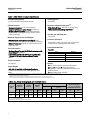
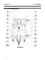
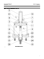
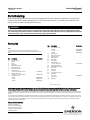
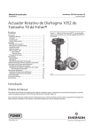
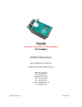
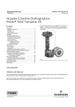
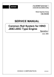
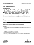
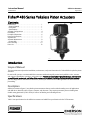
Instruction Manual
480 Series Actuators
D100291X012
August 2012
Fisherr 480 Series Yokeless Piston Actuators
Contents
Figure 1. Fisher 480-15 Piston Actuator
Introduction . . . . . . . . . . . . . . . . . . . . . . . . . . . . . . . . . 1
Scope of Manual . . . . . . . . . . . . . . . . . . . . . . . . . . . . . 1
Description . . . . . . . . . . . . . . . . . . . . . . . . . . . . . . . . . 1
Specifications . . . . . . . . . . . . . . . . . . . . . . . . . . . . . . . 1
Actuator Configurations . . . . . . . . . . . . . . . . . . . . . . . 4
Installation . . . . . . . . . . . . . . . . . . . . . . . . . . . . . . . . . . 5
Principle of Operation . . . . . . . . . . . . . . . . . . . . . . . . . 6
Pressure Connections . . . . . . . . . . . . . . . . . . . . . . . . . 7
Adjustments . . . . . . . . . . . . . . . . . . . . . . . . . . . . . . . . . 7
Actuator Maintenance . . . . . . . . . . . . . . . . . . . . . . . . . 8
Disassembly . . . . . . . . . . . . . . . . . . . . . . . . . . . . . . . . 8
Parts Ordering . . . . . . . . . . . . . . . . . . . . . . . . . . . . . . . 12
Parts List . . . . . . . . . . . . . . . . . . . . . . . . . . . . . . . . . . . 12
W1867
Introduction
Scope of Manual
This instruction manual provides installation, maintenance, and parts information for Fisher 480 Series yokeless piston
actuators.
Do not install, operate, or maintain 480 Series actuators without being fully trained and qualified in valve, actuator,
and accessory installation, operation, and maintenance. To avoid personal injury or property damage, it is important
to carefully read, understand, and follow all the contents of this manual, including all safety cautions and warnings. If
you have any questions about these instructions, contact your Emerson Process Management sales office before
proceeding.
Description
480 Series actuators (figure 1) are yokeless piston actuators that are used in either throttling or on-off applications
with ball valves, butterfly valves, louvers, dampers, and rheostats. They require pneumatic pressure loading from
double-acting positioners (Fisher 3570) or from on-off loading and unloading devices.
Specifications
Table 1 lists specifications for the 480 Series actuator and table 3 lists specifications for the 3570 actuator.
www.Fisher.com
Instruction Manual
480 Series Actuators
August 2012
D100291X012
Table 1. Fisher 480 Series Actuator Specifications
Stroking Speeds
Available Configurations
See table 2
See the Actuator Configurations section.
Operative Ambient Temperature(2)
Cylinder Pressure
With Nitrile O-Rings: -46 to 80_C (-50 to 175_F)
With Fluorocarbon O-Rings (Optional):(3)
-18 to 149_C (0 to 300_F)
Maximum Allowable:(4) 10.3 bar (150 psig)
Required to Produce a Given Thrust: See figure 2
Minimum Recommended: Valves with low torque
requirements -- (2.4 bar [35 psig]); all other valves -(3.4 bar [50 psig])
Actuator Size and Piston Size
See table 2
Maximum Supply Source Consumption
Pressure Connections
With Positioner and Constant Input Signal: 0.54
normal m3/hr(1) (20 scfh(1)) of air at 6.9 bar (100 psig)
Without Positioner: Depends on cylinder volume and
supply pressure
Standard is 1/4 NPT. For larger sizes, contact your
Emerson Process Management sales office.
Construction Materials
Actuator:
Travel Information
Maximum Rated Travels, All 480 Series actuators with
Linear Output: See table 2
Travel Stops Available for 480 Series actuators with
105 mm (4.125 inch ) Maximum Rated Travels: See
table 2
Part
Material
Cylinder and Piston
Aluminum
Piston Rod Extension
SST, Chrome Plated
Cylinder Seal Bushings
Brass
O-Rings
Nitrile or Fluorocarbon
Thrust Information
See figure 2
Options
J 376 Series trip valve system to fail actuator
J up or J down or J lock in last position
J TopWorxt DXP M21GNEB electrical valve stem
position switch
J Micro-Switch limit switches
Torque Output
480, 480-15, and 480-16 (for butterfly valves):
Contact your Emerson Process Management sales
office
1. Normal m3/hr.- normal cubic meters per hour (0_C and 1.01325 bar, absolute); Scfh - standard cubic feet per hour (60_F and 14.7 psia).
2. These terms are defined in ANSI/ISA Standard S51.1
3. Without snubber. If this actuator has a snubber, the temperature specification is the same for the nitrile version.
4. The pressure limits in this bulletin and any applicable standard or code limitation for actuator should not be exceeded.
Table 2. Size, Piston, Stroking Speed, and Travel Information
ACTUATOR
SIZE
EFFECTIVE
PISTON AREA
Cm2
PISTON
DIAMETER
Inch2
mm
STROKING
SPEED(1)
Inch
mm/
s
SINGLE-FLANGE
–16 Versions
All Others Except Fisher 487,
487-1(2)
TRAVEL STOPS AVAILABLE
FOR ACTUATORS WITH
105 mm (4.125 INCHES)
MAXIMUM RATED TRAVEL
Inch/s
mm
Inch
mm
Inch
mm
Inch
30
107
16.5
121
4.75
102
4
---
---
105
4.125
89
3.5
40
60
182
258
28.25
55.5
156
216
6.125
8.5
52
33
2.05
1.30
206
8.125
105
4.125
89
3.5
1. For actuators with positioners at 6.9 bar (100 psig) supply pressure and all prestroke conditions satisfied. Stroking speeds for actuators without positioners or with snubbers will depend on
the particular construction involved.
2. See 480 series Actuators Specifications for these travels.
2
Instruction Manual
480 Series Actuators
D100291X012
August 2012
Table 3. Fisher 3570 Actuator Specifications
Available Configurations
3570: Valve positioner with two relays and three
pressure gauges for monitoring input signal and
output pressures to the top and underside of the
actuator piston
3570C: Similar to 3570 except that the positioner is
equipped with automotive tire valves instead of
pressure gauges. The valves can be used for clip-on
test pressures gauges. The relay nozzles on these
positioners are locked in place with locknuts to resist
unwanted nozzle movement due to vibration
Input Signal
Standard Ranges: 0.2 to 1.0 bar (3 to 15 psig) or 0.4
to 2.0 bar (6 to 30 psig)
Split Ranges: Typically uses one half of standard range
when two control valves are operated by one input
signal from a single controller
Optional Ranges: As required within the limits of the
bellows
Bellows Pressure Rating
Standard Bellows: 3.4 bar (50 psig)
Optional Bellows: 6.2 bar (90 psig)
Supply Pressure
Maximum: 10.3 bar (150 psig)
Minimum: 2.4 bar (35 psig)
Output Signal
Type: Pneumatic pressure as required by the actuator
Action: Field reversible between direct and reverse
(see table 4)
Hysteresis(1,2)
0.15% of total stroke or instrument pressure span
Resolution(1,2)
0.2% of instrument pressure span
Repeatability(1,2)
0.3% of instrument pressure span
Frequency Response(1,2)
See figure 3
Pressure Connections
Vent: 3/8 NPT
All Others: 1/4 NPT
Pressure Indications
3570C: Tire valves accept standard pressure gauge
chucks
3570: See table below
Type of Indication
Number
Used
Standard Gauge Range
bar (psig)
Positioner input signal
gauge
1
0 to 2.1 (0 to 30) or
0 to 4.1 (0 to 60)
Cylinder supply pressure
gauge
0
0 to 11.0 (0 to 160)
Static Air Consumption(3)
0.56 normal m3/hr (20 scfh) with 6.9 bar
(100 psig) supply pressure
Operative Ambient Temperature(1,2)
With Nitrile O-Rings: -34 to 79_C (-30 to 175_F)
With Fluorocarbon O-Rings (Optional):(3)
-18 to 149_C (0 to 300_F)
Construction Materials
Actuator:
Part
Material
Base, Cover and Beam
Bellows
Bias and Range Spring
Relay Body
Relay Nozzle(s)
Diaphragm
O-Rings
Aluminum, die cast
Brass
Steel, Plated
Zinc, Die Cast
SST
Nitrile or Fluorocarbon
Nitrile or Fluorocarbon
Options
Fisher SS-52 clip-on chuck (with or without gauge) for
3570C positioners
1. These terms are defined in ANSI/ISA Standard S51.1
2. For actuator with positioner only. Does not apply to other constructions or actuator-valve combination.
3. Normal m3/hr.- normal cubic meters per hour (0_C and 1.01325 bar, absolute); Scfh - standard cubic feet per hour (60_F and 14.7 psia).
3
Instruction Manual
480 Series Actuators
August 2012
D100291X012
Figure 2. Supply Pressure and Thrusts
SIZE 30
ACTUATOR
SIZE 40
ACTUATOR
SIZE 60
ACTUATOR
THRUSTS IN THOUSANDS OF POUNDS (IN THOUSANDS OF NEWTONS)
FOR ACTUATORS WITH POSITIONERS
NOTE:
A5961
MAY BE INCREASED BY 10% FOR ACTUATORS WITHOUT POSITIONERS.
EITHER THIS THRUST, OR THE MAXUMUM ALLOWABLE LOADING FOR THE CONTROL
DEVICE IS THE LIMITING FACTOR FOR USABLE ACTUATOR FORCE.
Figure 3. Frequency Response
1. SIZE 30– 19mm (0.75 INCH) TRAVEL
2. SIZE 40– 38mm (1.5 INCH) TRAVEL
3. SIZE 60– 38mm (1.5 INCH) TRAVEL
A5962
Actuator Configurations
480: Yokeless piston actuator with positioner.
481: Yokeless piston actuator without positioner. Other actuators may be obtained without positioner by adding -1 to
the type number.
The above actuators come with standard mounting flange, 105 mm (4.125 inch) maximum rated travel, and threaded
piston rod connection with sizes 30 through 60 for mounting on ball valves, louvers, and dampers with brackets.
These actuators may be obtained with the following alternate universal mounting flange constructions:
-15 Added to Type Number: Allows butterfly valve mounting for a standard actuator with 105 mm (4.125 inch)
maximum travel and threaded piston rod connection, and comes in sizes 30 through 60.
-16 Added to Type Number: Provides 206 mm (8.125 inch) maximum travel and threaded piston rod connection, and
comes in sizes 40 through 60.
4
Instruction Manual
480 Series Actuators
D100291X012
August 2012
Table 4. Action Under Normal Operating Conditions
DESIRED PISTON MOTION
ACTUATOR DESCRIPTION
With Positioner
Down
Up
Direct-acting
Increasing input signal pressure to bellows(1)
Decreasing input signal pressure to bellows(1)
Reverse-acting
Decreasing input signal pressure to bellows(1)
Increasing input signal pressure to bellows(1)
Supply pressure loaded on top of piston,
exhausted from bottom
Supply pressure loaded on bottom of piston,
exhausted from top
Without positioner
1. Supply pressure is routed through relays to piston.
Installation
WARNING
Always wear protective gloves, clothing, and eyewear when performing any installation operations to avoid personal
injury.
Personal injury or equipment damage caused by sudden release of pressure may result if the valve assembly is installed
where service conditions could exceed the limits given in table 1 or 3 or on the appropriate nameplates. To avoid such
injury or damage, provide a relief valve for overpressure protection as required by accepted industry or local, state, and
Federal codes and good engineering practices.
Check with your process or safety engineer for any additional measures that must be taken to protect against process
media.
If installing into an existing application, also refer to the WARNING at the beginning of the Maintenance section in this
instruction manual.
Inspect this equipment on arrival to note any damage which may have occurred in transit. If the actuator is attached to
a valve body when received, install the valve in the pipeline with flow in the direction of the arrow on the valve body.
(Some valve types, notably various butterfly valves, can be installed with flow in either direction and are unmarked as
to proper flow direction.)
A three-valve bypass around the main valve is recommended to permit continuous operation during periodic
maintenance or inspection of the main valve.
Figure 4. Operation of Actuator with Positioner
FIXED RESTRICTION
RANGE SPRING
BIAS
SPRING
BELLOWS REVERSED
POSITION
RELAY B
INSTRUMENT
BEAM
SUPPLY
SUPPLY
BJ8256-A
A1286
RELAY A
FIXED RESTRICTION
INSTRUMENT PRESSURE
SUPPLY PRESSURE
TOP CYLINDER PRESSURE
BOTTOM CYLINDER PRESSURE
NOZZLE PRESSURE
5
Instruction Manual
480 Series Actuators
August 2012
D100291X012
When 480 Series actuators are supplied to operate dampers, louvers, or similar equipment, a suitable mounting plate
should be provided, and the piston rod of the actuator connected to the operating arm of the damper, etc., with
appropriate linkage.
Figure 5. Cylinder Diameter and Bolt Center Location, All Actuators (refer to table 5)
BH9452-K
A1290
Table 5. Cylinder Diameter and Bolt Center Location, All Actuators
ACTUATOR SIZE
C
H, DEGREE OF ARC
mm
Inch
Standard Flange
Universal Mounting Flange
30
171
6.75
0
45
40
206
8.12
45
45
60
267
10.50
22.5
45
Figure 6. Operation of Actuator with Snubber
SNUBBER
CHECK
VALVES
POSITIONER
OR SWITCH
-ING DEVICE
SUPPLY PRESSURE
TOP CYLINDER PRESSURE
BOTTOM CYLINDER PRESSURE
UPPER SNUBBER PRESSURE
LOWER SNUBBER PRESSURE
32A8303-A
A1287
Principle of Operation
Actuator
These actuators react to a pressure unbalance that is created by loading supply pressure on one side of the piston and
unloading the opposite side. Some type of switching device is required to shift the supply pressure from one side of
6
Instruction Manual
D100291X012
480 Series Actuators
August 2012
the piston to the other. For most actuators in the 480 Series, this device is a 3570 positioner. However, a separate
loading device must be provided for actuators without positioners.
For actuators with positioners (figure 4), the pneumatic output signal from a controller or instrument is piped to the
positioner bellows. As long as the bellows receives a constant input signal pressure, the beam remains motionless and
allows supply pressure to bleed through both relay nozzles so that a constant pressure is maintained between the
nozzle and the fixed orifice. The relays are in equilibrium with their inlet and exhaust valves closed.
Assume that a downward piston motion is required and the bellows receives a corresponding change in input signal
pressure. This causes the beam to pivot so that it covers the nozzle on relay A. (Beam movement is accomplished
either by increasing the input signal pressure on a direct-acting positioner to expand the bellows, or by decreasing the
input signal pressure on a reverse-acting positioner to contract the bellows.)
The nozzle pressure in relay A increases due to the restriction created by the beam over the nozzle. Through relay
action, the air pressure to the top of the piston is increased. At the same time, relay B reacts to the change in beam
position to decrease the pressure to the underside of the piston. Due to the resulting unbalanced forces acting on the
piston, it moves down, changing the valve plug position.
Piston movement is fed back to the beam by means of a range spring which is connected to the beam and to the
piston rod extension, applying a force to the beam opposite to that caused by the expanding or contracting bellows.
This feedback arrangement prevents overcorrection and ensures a definite position of the piston and valve plug for a
given instrument signal.
If upward piston motion is required, the beam pivots over the nozzle on relay B. The result is relay, piston, and
feedback action opposite that for downward piston motion.
Reversal of positioner action is accomplished simply by removing four screws, inverting the bellows, and installing two
bellows posts for support it the change is from direct to reverse action. Bellows posts are stored in the positioner case
and are not used if the change is from reverse to direct.
Actuator with Snubber
As the actuator piston strokes, the snubber piston moves inside an oil-filled cylinder, forcing oil from one side of the
piston to the other through two check valves (see figure 6). The resistance to flow created by the settings of the check
valves and the shock absorbing quality of the oil combine to damp out any tendency of the valve plug to jump. The
plug of each check valve is held off its seat by the positioning of the adjusting screws. Thus, with the adjusting screws
backed off all the way, maximum damping will be obtained.
Pressure Connections
480
The 3570 positioner, an integral part of 480 actuator units, is factory-assembled to the actuator. Two connections,
“Supply” and “Instrument”, remain to be made after valve installation. Both are 1/4 NPT holes in the positioner and are
labelled. Minimum supply pressure is 2.4 bar (35 psig), but for optimum performance, supply pressure should be held
as near as possible to the 10.3 bar (150 psig) maximum. Supply pressure air or gas should be clean and dry, as well as
non-corrosive. Use of a Fisher 252 filter is recommended.
The positioner case should always be vented to prevent pressure buildup. If the valve is installed with the actuator
below the pipeline, provide a new vent location in the lowest part of the case by removing the cadmium-plated pipe
plug from the case and screwing it into the standard vent location. This also serves as a drain hole to prevent
accumulation of condensate.
7
480 Series Actuators
August 2012
Instruction Manual
D100291X012
481
The 481 actuator also requires 1/4 NPT external supply pressure piping. The 481 has only a pressure tap cover on top
of the cylinder. Supply air pressure must be connected to it, and also to the lower cylinder connection located near the
cylinder/cylinder flange joint. An external four-way valve or other switching device must be provided between the
main supply pressure line and these two actuator pressure connections.
Adjustments
All three adjustments on the 480 actuator are on the 3570 positioner. For further information on the positioner, such
as Adjustments, Maintenance, Reversing, and Relay Operation,refer to the Fisher 3570 instruction manual,
D200137X012.
The 481 actuator requires no adjustments.
Actuator Maintenance
WARNING
Avoid personal injury from sudden release of process pressure. Before performing any maintenance operations:
D Do not remove the actuator from the valve while the valve is still pressurized.
D Always wear protective gloves, clothing, and eyewear when performing any maintenance operations to avoid personal
injury.
D Disconnect any operating lines providing air pressure or a control signal to the actuator. Be sure the actuator cannot
suddenly open or close the valve.
D Use bypass valves or completely shut off the process to isolate the valve from process pressure. Relieve process pressure
on both sides of the valve. Drain the process media from both sides of the valve.
D Use lock-out procedures to be sure that the above measures stay in effect while you work on the equipment.
D The valve packing box may contain process fluids that are pressurized, even when the valve has been removed from the
pipeline. Process fluids may spray out under pressure when removing the packing hardware or packing rings.
D Check with your process or safety engineer for any additional measures that must be taken to protect against process
media.
It is necessary for efficient and proper operation of the actuator that all parts be free from dirt, abrasives, and foreign
material. Upon assembly at the factor, all synthetic rubber O-rings have been coated with water-resistant lithium
grease. It is recommended that this lubricant be used on all O-rings, especially those on moving parts or in contact
with moving parts, whenever the actuator is dismantled.
Disassembly
Refer to figures 7 and 8.
References to “positioner” can be ignored if a 481 actuator is involved.
8
Instruction Manual
D100291X012
480 Series Actuators
August 2012
1. Bypass the valve body or shut off the pressure in the pipeline.
CAUTION
The adjustable linkage between the actuator and the main valve should not be disconnected when the valve is open with
fluid flowing. (Dampers or louvers should be in safe, stable positions prior to disconnection.)
2. Shut off all pressure to the actuator. Remove all tubing lines (cylinder, instrument, and supply) from the actuator.
3. Remove the positioner cover after loosening the four cover screws on the underside of the positioner base.
4. Disengage the range spring by unscrewing the spring retainer from the piston rod extension.
5. Loosen the two cap screws that hold the positioner to the cylinder. When removing the positioner, do not lose the
small O-ring that is used in the passage from the positioner to the top of the cylinder.
6. Next remove the clevis bolt from the adjustable linkage. Remove the bottom snap ring (key 26) and unscrew the
clevis and the boot locknut from the actuator piston rod.
7. Remove the nuts that hold the cylinder to the mounting flange and lift off the cylinder.
8. Remove the stud bolts (key 123) that hold the cylinder to the cylinder flange. Two slots, 180 degrees apart, are
located at the lower edge of the cylinder. Insert a screwdriver in these slots and pry the cylinder loose. The piston
and piston rod will come out with the cylinder. the piston can then be removed by pulling it out the open end of the
cylinder.
9. Unscrew both seal bushings (keys 7 and 8).
10. Inspect all parts for excessive wear and defects. Replace all worn O-rings. Lubricate as mentioned above.
11. To reassemble, reverse the above procedure.
Note
When reassembling the actuator after the piston rod extension (key 5) has been removed from the piston rod (key 4), clean the
threads of the piston rod thoroughly and apply a thread locking adhesive (medium strength) to the threads. Tighten the piston rod
extension securely to a torque of 203 NSm (150 lbfSft). This torque is approximately equal to the torque that would be developed
by placing a force of 150 pounds on the end of a one-foot wrench, 75 pounds on the end of a two-foot wrench, etc.
9
Instruction Manual
480 Series Actuators
August 2012
D100291X012
Figure 7. Fisher 480 Piston Actuator - Size 30- 60
PARTS NOT SHOWN: 27 AND 112
40A9540-A
10
Instruction Manual
480 Series Actuators
D100291X012
August 2012
Figure 8. Fisher 481 Piston Actuator - Size 30- 60
PARTS NOT SHOWN: 27, 78, 79, AND 112
40A9538-A
11
Instruction Manual
480 Series Actuators
August 2012
D100291X012
Parts Ordering
When corresponding with your Emerson Process Management sales office about this equipment, refer to the serial
number found on the actuator nameplate (key 22). Also, specify the complete 11-character part number from the
following Parts List when ordering replacement parts.
WARNING
Use only genuine Fisher replacement parts. Components that are not supplied by Emerson Process Management should
not, under any circumstances, be used in any Fisher valve, because they may void your warranty, might adversely affect the
performance of the valve, and could cause personal injury and property damage.
Parts List
Note
Part numbers are shown for recommended spares only. For part
numbers not shown, contact your Emerson Process Management sales
office.
Key
Description
1
2
3
4
5
7
8
9*
Cylinder Flange
Cylinder
Piston
Piston Rod
Piston Rod Extension
Upper Seal Bushing
Lower Seal Bushing
Stem Seal O-ring
Sizes 30, 40, and 60 (2 req'd)
Bushing Seal O-ring
Sizes 30, 40, and 60 (2 req'd)
Piston Seal O-ring
Size 30
Size 40
Size 60
10*
11*
Part Number
1E73690699
1D34830689
1H86210699
1H86220699
1H86240699
Key
Description
12*
Cylinder Seal O-ring
Size 30
Size 40
Size 60
Cylinder Stud
Compression Fitting
Cylinder Tubing
Boot Locknut
Nameplate
Drive Screw
Piston Rod Boot
Sizes 30, 40, and 60
Top Boot Snap Ring
Bottom Boot Snap Ring
Travel stop
Piston Nut
Positioner
Spring Retainer Spacer
Cover Seal
481 only
Cover Screw
Pipe Plug
13
14
15
18
22
23
24*
25
26
27
30
31
45
78*
79
160
Part Number
1H86200699
1D44480699
1H86230699
1H93790699
1C85380699
*Recommended spare parts
Neither Emerson, Emerson Process Management, nor any of their affiliated entities assumes responsibility for the selection, use or maintenance
of any product. Responsibility for proper selection, use, and maintenance of any product remains solely with the purchaser and end user.
Fisher and TopWorx are marks owned by one of the companies in the Emerson Process Management business unit of Emerson Electric Co. Emerson Process
Management, Emerson, and the Emerson logo are trademarks and service marks of Emerson Electric Co. All other marks are the property of their respective
owners.
The contents of this publication are presented for informational purposes only, and while every effort has been made to ensure their accuracy, they are not
to be construed as warranties or guarantees, express or implied, regarding the products or services described herein or their use or applicability. All sales are
governed by our terms and conditions, which are available upon request. We reserve the right to modify or improve the designs or specifications of such
products at any time without notice.
Emerson Process Management
Marshalltown, Iowa 50158 USA
Sorocaba, 18087 Brazil
Chatham, Kent ME4 4QZ UK
Dubai, United Arab Emirates
Singapore 128461 Singapore
www.Fisher.com
12
E 2007, 2012 Fisher Controls International LLC. All rights reserved.