1
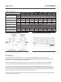
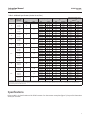
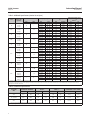
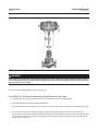
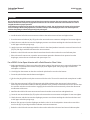
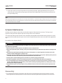
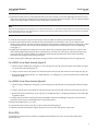
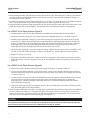
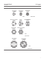
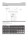
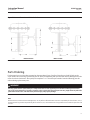
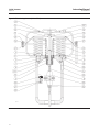
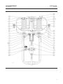
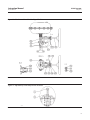
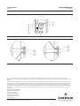
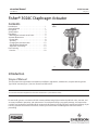
Instruction Manual
3024C Actuator
D103048X012
May 2011
Fisherr 3024C Diaphragm Actuator
Contents
Introduction . . . . . . . . . . . . . . . . . . . . . . . . . . . . . . . . . 1
Scope of Manual . . . . . . . . . . . . . . . . . . . . . . . . . . . . . . 1
Description . . . . . . . . . . . . . . . . . . . . . . . . . . . . . . . . . . 2
Specifications . . . . . . . . . . . . . . . . . . . . . . . . . . . . . . . . 3
Installation . . . . . . . . . . . . . . . . . . . . . . . . . . . . . . . . . . . 5
Mounting the Actuator on the Valve . . . . . . . . . . . . 5
Actuator Maintenance . . . . . . . . . . . . . . . . . . . . . . . . . 8
Disassembly . . . . . . . . . . . . . . . . . . . . . . . . . . . . . . . . 8
Assembly . . . . . . . . . . . . . . . . . . . . . . . . . . . . . . . . . . . 9
Changing the Actuator Action . . . . . . . . . . . . . . . . . 12
Side‐Mounted Handwheel . . . . . . . . . . . . . . . . . . . . 12
Adjustable Travel Stops . . . . . . . . . . . . . . . . . . . . . . 13
Parts Ordering . . . . . . . . . . . . . . . . . . . . . . . . . . . . . . . 15
Parts List . . . . . . . . . . . . . . . . . . . . . . . . . . . . . . . . . . 18
Figure 1. Fisher 3024C Actuator with Sliding‐Stem
Valve
W8488
Introduction
Scope of Manual
This instruction manual provides information on installation, adjustment, maintenance, and parts ordering for the
Type 3024C actuator (figure 1) for sizes 30 to 45 and 30E to 45E.
Note
This manual assumes throughout that the valve construction is “push‐down‐to‐close.”
Do not install, operate, or maintain a 3024C actuator without being fully trained and qualified in valve, actuator, and
accessory installation, operation, and maintenance. To avoid personal injury or property damage, it is important to
carefully read, understand, and follow all the contents of this manual, including all safety cautions and warnings. If you
have any questions about these instructions, contact your Emerson Process Management sales office before
proceeding.
www.Fisher.com
Instruction Manual
3024C Actuator
May 2011
D103048X012
Table 1. Specifications
Specification
Actuator Size
34E
40
40E
See tables 2 and 3.
6
87
‐‐‐
16
‐‐‐
32
‐‐‐
0.75
‐‐‐
0.75
‐‐‐
2
2‐1/8
2‐1/8
2‐1/8
2‐13/16
2‐13/16
(54 mm)
(54 mm)
(54 mm)
(71 mm)
(71 mm)
‐‐‐
M12 x 1.75
‐‐‐
M16 x 2
‐‐‐
3/8‐24
‐‐‐
3/8‐24
‐‐‐
1/2‐20
Nitrile diaphragm and steel studs and nuts: -40 to +82
Nitrile diaphragm and steel studs and nuts: -40 to +180
1/4 – 18 NPT
9.5
18.0
18.0
19.5
21.5
20.9
39.7
39.7
43.0
47.4
16.5
25.0
25.0
26.5
28.5
36.4
55.1
55.1
58.4
62.8
30
30E
Nominal Effective Area
Bar
psig
mm
Inch
Inch
(mm)
mm
Inch
_C
_F
Inch
kg
lb
kg
lb
Maximum Operating Pressure
to Diaphragm
Maximum Travel
Yoke Boss Diameter
Valve Stem Connector Thread
Temperature Range
Pressure Connections
Maximum Approximate
Weight (without handwheel)
Maximum Approximate
Weight (with handwheel)
16
‐‐‐
2‐1/8
(54 mm)
M12 x 1.75
‐‐‐
9.5
20.9
16.5
36.4
Figure 2. Schematic of Fisher 3024C
45
45E
32
‐‐‐
2‐13/16
(71 mm)
M16 x 2
‐‐‐
‐‐‐
2
2‐13/16
(71mm)
‐‐‐
1/2‐20
33.5
73.9
40.5
89.3
35.5
78.3
42.5
93.7
Figure 3. Fisher 3024C Actuator Nameplate
SPRINGS PUSH
STEM DOWN
AIR PUSHES
STEM DOWN
SPRINGS LIFT
STEM UP
34
STEM SEAL
STEM
AIR LIFTS
STEM UP
STEM
1Q574760
1Q57489
AIR‐TO‐CLOSE (ATC)
AIR‐TO‐OPEN (ATO)
Description
The 3024C direct acting (extends stem/air‐to‐close) actuator (figure 8) and the reverse acting (retracts
stem/air‐to‐open) actuator (figure 9) are spring‐opposed pneumatic diaphragm actuators that provide automatic
throttling or on‐off operation of sliding‐stem control valves.
The actuator will position the valve plug in response to varying pneumatic loading pressure on the actuator
diaphragm. Figure 2 shows the operation of an ATC (air‐to‐close) actuator and an ATO (air‐to‐open) actuator.
The 3024C ATC (air‐to‐close) actuator springs are located under the diaphragm plate and they fully retract the
actuator stem for fail action upon loss of diaphragm casing pressure. The 3024C ATO (air‐to‐open) actuator springs
are located on top of the diaphragm plate and they fully extend the actuator stem upon loss of diaphragm casing
pressure. The actuator is mounted on the valve by means of a cast yoke.
The 3024C can be equipped with a side mounted handwheel if required (figure 10). An adjustable up travel stop can
also be fitted (figures 11 and 12).
2
Instruction Manual
3024C Actuator
D103048X012
May 2011
Table 2. Additional Specifications (Action Air‐to‐Close)
Travel
Spring Range
Size
Spring Set/
Quantity
mm
Inch
30
217/3
218/5
218/7
16
---
30E
217/3
218/5
218/7
---
0.75
219/3
212/5
212/7
16
---
34E
219/3
212/5
212/7
---
0.75
40
212/3
213/6
214/7
32
---
212/3
213/6
214/7
---
1.125
213/4
214/5
214/7
---
1.5
213/4
214/5
214/7
---
2
221/8
221/12
223/12
32
---
221/8
221/12
223/12
---
1.125
221/8
221/12
223/12
---
1.5
221/8
221/12
223/12
---
2
34
40E
45
45E
Bar
0.3 ‐ 1.1
1.3 ‐ 2.0
1.8 ‐ 2.9
0.3 ‐ 1.3
1.3 ‐ 2.2
1.8 ‐ 3.0
0.3 ‐ 1.1
0.9 ‐ 1.7
1.3 ‐ 2.3
0.3 ‐ 1.3
0.9 ‐ 1.8
1.3 ‐ 2.5
0.4 ‐ 1.3
0.8 ‐ 1.8
1.2 ‐ 2.4
0.4 ‐ 1.2
0.8 ‐ 1.7
1.2 ‐ 2.3
0.3 ‐ 1.0
0.6 ‐ 1.5
0.9 ‐ 2.1
0.2 ‐ 1.2
0.5 ‐ 1.7
0.7 ‐ 2.4
0.8 ‐ 1.6
1.2 ‐ 2.5
1.5 ‐ 3.1
0.8 ‐ 1.6
1.2 ‐ 2.3
1.5 ‐ 3.0
0.5 ‐ 1.4
0.8 ‐ 2.2
1.0 ‐ 2.7
0.5 ‐ 1.7
0.7 ‐ 2.5
0.9 ‐ 3.1
Psig
4 ‐ 16
19 ‐ 29
26 ‐ 42
4 ‐ 19
19 ‐ 32
26 ‐ 44
4 ‐ 16
13 ‐ 25
19 ‐ 33
4 ‐ 19
13 ‐ 26
19 ‐ 36
6 ‐ 19
12 ‐ 26
17 ‐ 35
6 ‐ 17
12 ‐ 25
17 ‐ 33
4 ‐ 15
9 ‐ 22
13 ‐ 30
3 ‐ 17
7 ‐ 25
10 ‐ 35
12 ‐ 23
17 ‐ 36
22 ‐ 45
12 ‐ 23
17 ‐ 33
22 ‐ 44
7 ‐ 20
12 ‐ 32
15 ‐ 39
7 ‐ 25
10 ‐ 36
12 ‐ 45
Effective Diaphragm Area
(1)
cm2
160
160
160
160
160
160
400
400
400
400
400
400
390
390
390
390
390
390
380
380
380
370
370
370
790
790
790
790
790
790
780
780
780
770
770
770
Inches2
24.8
24.8
24.8
24.8
24.8
24.8
62.0
62.0
62.0
62.0
62.0
62.0
60.5
60.5
60.5
60.5
60.5
60.5
58.9
58.9
58.9
57.4
57.4
57.4
122
122
122
122
122
122
121
121
121
119
119
119
Maximum Output Thrust
(Maximum Actuator Stem
Force) (2)
N
Lb
7840
1760
6400
1440
4960
1120
7520
1690
6080
1360
4800
1070
19,600
4400
17,200
3840
14,800
3350
18,800
4220
16,800
3780
14,000
3160
18,300
4110
16,400
3690
14,000
3150
18,700
4230
16,800
3750
14,400
3270
19,000
4240
17,100
3830
14,800
3360
17,800
4220
15,900
3560
13,300
2980
34,800
7810
27,600
6220
22,900
5120
34,800
7810
29,200
6590
23,700
5250
35,900
8110
29,600
6650
25,700
5810
33,100
7380
26,900
6070
22,300
5000
1. Effective diaphragm area at 0% valve travel from seat.
2. Based upon 6 bar operating pressure to the diaphragm and valve travel at 0% from seat. This does not consider limitation to the valve such as stem buckling load. Consult your Emerson
Process Management sales office for details.
Specifications
Refer to table 1 for Specifications of the 3024C actuator. See the actuator nameplate (figure 3) for specific information
about your actuator.
3
Instruction Manual
3024C Actuator
May 2011
D103048X012
Table 3. Additional Specifications (Action Air‐to‐Open)
Travel
Spring Range
Size
Spring Set/
Quantity
30
217/3
218/5
218/7
30E
217/3
218/5
218/7
---
0.75
34
219/3
212/5
212/7
16
---
34E
219/3
212/5
212/7
---
0.75
40
212/3
213/6
214/7
32
---
212/3
213/6
214/7
---
1.125
213/4
214/5
214/7
---
213/4
214/5
214/7
---
2
221/8
221/12
223/12
32
---
221/8
221/12
223/12
---
1.125
221/8
221/12
223/12
---
1.5
221/8
221/12
223/12
---
2
mm
40E
45
45E
Inch
Bar
0.5 ‐ 1.3
1.4 ‐ 2.2
2.0 ‐ 3.1
0.3 ‐ 1.3
1.2 ‐ 2.2
1.8 ‐ 3.1
0.6 ‐ 1.4
1.1 ‐ 1.9
1.6 ‐ 2.7
0.4 ‐ 1.4
1.0 ‐ 1.9
1.4 ‐ 2.7
0.4 ‐ 1.3
0.8 ‐ 1.8
1.2 ‐ 2.4
0.5 ‐ 1.3
0.9 ‐ 1.8
1.3 ‐ 2.4
0.4 ‐ 1.1
0.7 ‐ 1.6
1.0 ‐ 2.3
0.2 ‐ 1.2
0.5 ‐ 1.8
0.8 ‐ 2.5
0.8 ‐ 1.7
1.2 ‐ 2.5
1.6 ‐ 3.2
0.9 ‐ 1.7
1.4 ‐ 2.5
1.7 ‐ 3.2
0.7 ‐ 1.6
1.1 ‐ 2.4
1.3 ‐ 3.1
0.5 ‐ 1.7
0.8 ‐ 2.6
0.9 ‐ 3.2
---
16
1.5
Effective Diaphragm Area
(1)
cm2
170
170
170
175
175
175
410
410
410
420
420
420
450
450
450
440
440
440
410
410
410
440
440
440
940
940
940
910
910
910
870
870
870
940
940
940
Psig
7 ‐ 19
20 ‐ 32
29 ‐ 45
4 ‐ 19
17 ‐ 32
26 ‐ 45
9 ‐ 20
16 ‐ 28
23 ‐ 39
6 ‐ 20
15 ‐ 28
20 ‐ 39
6 ‐ 19
12 ‐ 26
17 ‐ 35
7 ‐ 19
13 ‐ 26
19 ‐ 35
6 ‐ 16
10 ‐ 23
15 ‐ 33
3 ‐ 17
7 ‐ 26
12 ‐ 36
12 ‐ 25
17 ‐ 36
23 ‐ 46
13 ‐ 25
20 ‐ 36
25 ‐ 46
10 ‐ 23
16 ‐ 35
19 ‐ 45
7 ‐ 25
12 ‐ 38
13 ‐ 46
Inches2
26.4
26.4
26.4
27.1
27.1
27.1
63.6
63.6
63.6
65.1
65.1
65.1
69.8
69.8
69.8
68.2
68.2
68.2
63.6
63.6
63.6
68.2
68.2
68.2
146
146
146
141
141
141
135
135
135
146
146
146
Maximum Output Thrust
(Maximum Actuator Stem
Force) (2)
N
Lb
780
170
2360
530
3360
760
550
120
2180
490
3110
700
2450
550
4610
1040
6560
1480
1880
420
4120
930
5870
1320
1880
420
3640
820
5530
1240
2200
500
3970
890
5920
1330
1560
350
3010
680
4270
960
1060
240
2390
540
3400
760
7790
1750
11,700
2630
14,700
3300
8350
1880
12,500
2810
15,700
3530
6150
1380
9230
2080
11,500
2590
4740
1070
7110
1600
8800
1980
1. Effective diaphragm area at 0% valve travel from seat.
2. Based on zero operating pressure to the diaphragm and valve travel at 0% from valve seat. This does not consider limitations such as stem buckling load. Consult your Emerson Process
Management sales office for details.
Table 4. Handwheel Specifications
ACTUATOR
SIZE
HANDWHEEL DIAMETER
TURNS PER mm/INCH
TRAVEL
HANDWHEEL OUTPUT FORCE
mm
In.
mm
In.
N
lb
N
lb
30 and
30E
200
7.87
0.24
6.1
179
40
5000
1125
34, 34E,
40, and 40E
250
9.84
0.21
5.4
286
64
10,000
2250
45 and
45E
250
9.84
0.21
5.5
400
90
14,000
3150
1. Tangential handwheel force required to produce the handwheel output force shown.
2. Brass operating nut and stainless steel screw.
4
RIM
FORCE(1,2)
Instruction Manual
D103048X012
3024C Actuator
May 2011
Installation
WARNING
Always wear protective gloves, clothing, and eyewear when performing any installation operation to avoid personal injury.
Personal injury or equipment damage caused by sudden release of pressure may result if the actuator assembly is installed
where service conditions could exceed the limits given in tables 1, 2, and 3 or the appropriate nameplates. To avoid such
injury or damage, provide a relief valve for overpressure protection as required by accepted industry and governmental
codes and good engineering practices.
To avoid parts damage, do not use a normal operating pressure that exceeds the Maximum Diaphragm Casing Pressure
(see table 1) or produces a force on the actuator stem greater than the Maximum Allowable Output Thrust (see table 2 or 3)
or Maximum Allowable Valve Stem Load.
Check with your process or safety engineer for any additional measures that must be taken to protect against process
media.
When ordered, the valve configuration and construction materials were selected to meet particular pressure, temperature,
pressure drop, and controlled fluid conditions.
Responsibility for the safety of process media and the compatibility of valve materials with the process media rests solely
with the purchaser and end user. Since some valve body/trim materials combinations are limited in their pressure drop and
temperature ranges, do not apply any other conditions to the valve without first contacting your Emerson Process
Management sales office.
If installing into an existing application, also refer to the WARNING at the beginning of the Maintenance section in this
instruction manual.
A 3024C diaphragm actuator is normally shipped mounted on a valve. Refer to the appropriate valve instruction
manual when installing the valve in the pipeline. If the actuator is shipped separately or if it is necessary to mount the
actuator on the valve, perform the Actuator Mounting procedure given below. For information on mounting the
positioner, refer to the appropriate positioner instruction manual.
CAUTION
The 3024C actuators are designed to mount on push‐down‐ to‐close valves. Do not mount these actuators on any other
type of valve without first contacting your Emerson Process Management sales office.
Mounting the Actuator on the Valve
The following procedure describes how to mount a 3024C actuator on a push‐down‐to‐close valve so that the
actuator stem and valve stem thread engagement allows full travel and proper shut‐off. Refer to table 4 and figures 6
and 7 for actuator dimensions. Key numbers referenced in the following steps are shown in figures 8 and 9.
1. Provide a temporary method of applying diaphragm air loading pressure to the diaphragm to move the actuator
stem during adjustments.
2. Provide a vice or some other method of supporting the valve and the weight of the actuator during assembly.
3. Push the valve stem down until the valve plug is fully closed.
4. Screw the two stem locknuts (key 52) to the lower end of the valve stem thread.
5
Instruction Manual
3024C Actuator
May 2011
D103048X012
Figure 4. Actuator Mounting Components for Assembly with a Valve
W8484‐1
WARNING
When moving the actuator stem with diaphragm loading pressure use caution to keep hands and tools out of the actuator
stem travel path. Personal injury and/or property damage is possible if something is caught between the actuator stem and
other parts of the valve assembly.
Perform one of the following procedures as appropriate:
For a 3024C Air‐To‐Close Actuator with a Push‐Down‐to‐Close Valve:
a. Carefully place the actuator on the valve so that the yoke boss fits over the valve bonnet.
b. Screw the yoke lock nut onto the bonnet and tighten.
c. Lift the valve plug off the seat by the correct valve travel for the valve. This is stated on the nameplate or in table
1.
d. Place the stem connector half (key 50) approximately halfway between the actuator and valve stems but
observing the F dimension in table 5 so that any positioner lever (if fitted) is horizontal at mid‐travel. Be sure that
the actuator and valve stem threads are engaging the threads of the stem connector by at least the distance of
one diameter of the stem.
6
Instruction Manual
3024C Actuator
D103048X012
May 2011
CAUTION
Be sure that the length of the actuator stem and the valve stem in the connector (key 50) is equal to or greater than the
diameter of that stem. Incomplete engagement of either the valve or actuator stem in the stem connector can result in
stripped threads or improper operation.
In the following procedure do not rotate the valve plug while it is seated. This may damage the seating surface and cause
excessive leakage. While making adjustments, use tools carefully to avoid damaging the valve stem. A damaged stem
could cut the packing and allow leakage through the packing box.
e. Install the other half of the stem connector and insert the socket screws and nuts and tighten them.
f. Screw the two stem locknuts (key 52) up the valve stem to the stem connector and tighten. Do not over tighten.
g. Slowly decrease and then increase the diaphragm pressure several times stroking the valve from the lower end
to the upper end of the spring range.
h. Apply air pressure to the diaphragm until the valve is in the closed position. Loosen the screws of the travel scale
(key 26) and align it with the indicator on the stem connector.
i. Stroke the valve full travel to ensure that the travel matches the valve travel on the travel indicator plate.
j. If the valve travel is not correct, repeat the stem connector procedure. Remove the air pressure from the
diaphragm, remove the stem connector and repeat steps c to i.
For a 3024C Air‐to‐Open Actuator with a Push‐Down‐to‐Close Valve:
a. Apply approximately 0.5 bar pressure above the upper setting of the spring pressure range to the bottom of the
diaphragm. This positions the actuator stem (key 8) at the highest point. The spring range is stated on the
nameplate or in table 3.
b. Carefully place the actuator on the valve so that the yoke boss fits over the valve bonnet.
c. Screw the yoke lock nut onto the bonnet and tighten.
d. Lift the valve plug off the seat by the correct travel for the valve. The travel is stated on the nameplate or in table
1.
e. Place the stem connector half (key 50) approximately halfway between the actuator and valve stems but
observing the F dimension in table 5 so that any positioner lever (if fitted) is horizontal at mid‐travel. Be sure that
the actuator and valve stem threads are engaging the threads of the stem connector by at least the distance of
one diameter of the stem.
f. Install the other half of the stem connector and insert the socket screws and nuts and tighten them.
g. Screw the two stem locknuts (key 52) up the valve stem to the stem connector and tighten. Do not over tighten.
h. Slowly decrease and then increase the diaphragm pressure several times stroking the valve from the lower end
to the upper end of the spring range.
i. Remove all air pressure from the diaphragm so that the valve is in its closed position. Loosen the screws of the
travel scale (key 26) and align it with the indicator on the stem connector.
j. Stroke the valve full travel to ensure that the valve travel matches the valve travel on the travel indicator plate.
7
3024C Actuator
May 2011
Instruction Manual
D103048X012
k. If the valve travel is not correct repeat the stem connector procedure. Apply approximately 0.5 bar pressure
above the upper setting of the spring range to the bottom of the diaphragm, remove the stem connector and
then repeat steps d to j.
Note
When disassembling the stem connector on Air‐to‐Open constructions it is essential to apply enough air pressure to the underside
of the diaphragm to lift the valve plug off its seat. This will ensure that all residual spring compression in the actuator is supported
while the stem connector is removed.
Actuator Maintenance
Actuator parts are subject to normal wear and must be inspected and replaced as necessary. The frequency of
inspection and replacement depends upon the severity of the service conditions.
This section describes how the actuator can be completely disassembled and assembled. When inspection or repairs
are required, disassemble only those parts necessary to accomplish the job; then start to assemble at the appropriate
step.
Key numbers refer to figures 8 and 9.
WARNING
Avoid personal injury or property damage from sudden release of process pressure or bursting of parts. Before performing
any maintenance operations:
D Do not remove the actuator from the valve while the valve is still pressurized.
D Always wear protective gloves, clothing, and eyewear when performing any maintenance operations to avoid personal
injury.
D Disconnect any operating lines providing air pressure, electric power, or a control signal to the actuator. Be sure the
actuator cannot suddenly open or close the valve.
D Use bypass valves or completely shut off the process to isolate the valve from process pressure. Relieve process pressure
from both sides of the valve. Drain the process media from both sides of the valve.
D Vent the power actuator loading pressure and relieve any actuator spring precompression.
D Use lock‐out procedures to be sure that the above measures stay in effect while you work on the equipment.
D The valve packing box may contain process fluids that are pressurized, even when the valve has been removed from the
pipeline. Process fluids may spray out under pressure when removing the packing hardware or packing rings, or when
loosening the packing box pipe plug.
D Check with your process or safety engineer for any additional measures that must be taken to protect against process
media.
Disassembly
1. For complete disassembly, the positioner and all accessories (if attached) must be removed from the actuator.
Follow appropriate removal procedures in the instruction manuals supplied with the positioner and accessories.
8
Instruction Manual
3024C Actuator
D103048X012
May 2011
2. Bypass the control valve. For a top‐loaded 3024C Air‐to‐Close actuator, reduce the diaphragm air pressure to zero
and remove the piping or tubing from the connection in the upper diaphragm casing (key 16). For a bottom loaded
3024C Air‐to‐Open, apply air pressure to the diaphragm to open the valve.
Note
When disassembling the stem connector on Air‐to‐Open constructions, it is essential to apply enough air pressure to the underside
of the diaphragm to lift the valve plug off its seat. This will ensure that all residual spring compression in the actuator is supported
while the stem connector is removed.
3. Undo the stem connector by first slackening the valve stem locknuts and then removing the socket bolts.
4. Undo the yoke locknut on the valve bonnet and carefully lift the actuator off the valve. As you undo the yoke
locknut, ensure that the actuator is properly supported. If the actuator is a bottom loaded Air‐to‐Open type, reduce
the diaphragm pressure to zero and remove the piping or tubing from the connection in the lower diaphragm
casing (key 1).
5. Slightly loosen all diaphragm casing cap screws (key 19 and 21). Remove the plastic hose (key 22). Unscrew the
short and long diaphragm casing cap screws and nuts (keys 19, 20 and 21) alternately, until only the long casing
cap screws (key 21) remain engaged. Then allow the remaining spring compression to be slowly released by
alternately unscrewing the long casing cap screws.
6. When removing the diaphragm and actuator springs perform one of the following procedures as appropriate:
For a 3024C Air‐to‐Open Actuator (figure 9)
a. Lift off the upper diaphragm casing (key 16), the casing spacer (key 29) and seal ring (key 30) if fitted (see figure
13), and remove the springs (Key 15).
b. Using a strap wrench or soft‐jawed vice, hold the actuator stem (key 8) and remove the travel stop nut (key14).
c. Remove the diaphragm plate (key 13), diaphragm (key 11), O‐Ring (key 12), pressure plate (key10) and the split
ring halves (key 9).
For a 3024C Air‐to‐Close Actuator (figure 8)
a. Lift off the upper diaphragm casing (key 16) and casing spacer (key 29) and seal ring (key 30) if fitted (see figure
13).
b. Using a strap wrench or soft‐jawed vice, hold the actuator stem (key 8) and remove the travel stop nut (key14).
c. Remove the pressure plate (key 10), O‐ring (key 12), diaphragm (key 11), diaphragm plate (key 13) and the split
ring halves (key 9).
7. Carefully slide the actuator stem (key 8) out of the bottom of the lower diaphragm casing (key 1) and set it on a
protective surface to prevent damage to the O‐ring sealing surface.
8. Remove the bellows (key 31), if used.
9. Unscrew the cheese head screws (key 7), then remove the bushing (key 6).
10. With the actuator disassembled, inspect all parts for excessive wear and replace as necessary.
Assembly
This procedure assumes that the actuator is completely disassembled. If it is not, start the instructions at the
appropriate step.
9
3024C Actuator
Instruction Manual
May 2011
D103048X012
1. Before starting assembly, apply lithium grease (key 200) to the O‐ring in the bushing (key 6 and key 12). Install the
new bushing (key 6) and assemble with the cheese head screws (key 7) onto the lower diaphragm casing (key 1).
Use a torque of 0.4 NSm (3 lbfSin).
2. Assemble the ring halves (key 9), pressure plate (key 10), O‐ring (key 12), diaphragm (key 11) and diaphragm plate
(key 13) on to the actuator stem as shown in figure 9 for Air‐to‐Open or figure 8 for Air‐to‐Close.
3. Apply thread locking adhesive (high strength) (key 201) to the thread on the upper end of the actuator stem, fit the
travel stop nut (key 14) but do not tighten. Then perform one of the following procedures as appropriate.
For a 3024C Air‐to‐Open Actuator (figure 9)
a. Carefully slide the actuator stem (key 8) (with the assembled parts) down through the bushing (key 6).
b. Position the actuator springs (key 15) symmetrically on the diaphragm plate (key 13) as shown in figure 5.
c. Install the upper diaphragm casing (key 16) so that the springs fit correctly over the seat bosses of the spring
locator (key 17). Rotate the upper diaphragm casing along with the diaphragm/diaphragm plate assembly so
that the air connection in the upper diaphragm casing is located directly above the air connection in the lower
diaphragm casing. Then rotate the diaphragm without moving either the upper diaphragm casing or the
diaphragm plate so that the diaphragm holes line up with those in the casings.
d. Lift off the upper diaphragm casing and remove the springs. Tighten the travel stop nut (key 14 as follows: Sizes
30, 30E, 34, and 34E, tighten to 36 NSm (27 lbfSft); Sizes 40, 40E, 45, and 45E, tighten to 87 NSm 64 lbfSft).
e. Replace the spring as previously.
f. For actuator sizes 40E and 45E with 1.5 and 2 inch travels, a casing spacer is fitted between the upper and lower
diaphragm casings. Place the casing spacer (key 29) on the diaphragm and then the gasket (key 30) as shown in
figure 13.
For a 3024C Air‐to‐Close Actuator (figure 8)
a. Position the actuator springs symmetrically on the spring locator (key 17) as shown in figure 5.
b. For actuator sizes 40E and 45E with 1.5 and 2 inch travels, a casing spacer (key 29) is fitted between the upper
and lower diaphragm casings. Place the gasket (key 30) on the lower casing and then the casing spacer (key 29)
as shown in figure 13.
c. Carefully slide the actuator stem with the assembled parts down through the bushing and position it so that the
springs fit correctly over the seat bosses on the upper side of the diaphragm plate (key 13). Rotate the
diaphragm (key 11) without moving the diaphragm plate (key 13) so that the diaphragm holes line with the
lower diaphragm casing holes.
d. Tighten the travel stop nut (key 14) as follows: Sizes 30, 30E, 34 and 34E tighten to 36 NSm (27 lbfSft); Sizes 40,
40E, 45 and 45E tighten to 87 NSm (64 lbfSft).
4. Install the upper diaphragm casing (key 16) so that the air connection is located directly above the air connection in
the lower diaphragm casing (key 1). Using the long cap screws (key 21) and hex nuts (key 20) first, and then the
shorter cap‐screws (key 19) and hex nuts (key 20), bolt the two diaphragm casings together. Fit the safety plastic
hose (key 22) over the exposed thread of the long cap‐screws (key 21).
CAUTION
Over tightening the diaphragm cap screws and nuts can damage the diaphragm. Do not exceed the torque of 13 NSm (10
lbfSft) for sizes 30, 30E, 34 and 34E and 17 NSm ( 12 lbfSft) for sizes 40, 40E, 45, and 45E.
10
Instruction Manual
3024C Actuator
D103048X012
May 2011
Figure 5. Fisher 3024C Spring Arrangements
SIZE 30 AND 30E
3 SPRINGS
SIZE 30 AND 30E
7 SPRINGS
SIZE 30 AND 30E
5 SPRINGS
SPRING LOCATOR
SPRING
SIZE 34, 34E, 40, AND 40E
3 SPRINGS
SIZE 40 AND 40E
6 SPRINGS
SIZE 40E
4 SPRINGS
SIZE 34, 34E, AND 40E
5 SPRINGS
SIZE 34, 34E, 40, AND 40E
7 SPRINGS
SPRING
SPRING LOCATOR
SIZE 45 AND 45E
8 SPRINGS
SIZE 45 AND 45E
12 SPRINGS
SPRING
SPRING LOCATOR
2Q57503
11
3024C Actuator
May 2011
Instruction Manual
D103048X012
Note
Be sure to use the long cap screws (key 21) first, installing them on opposite sides of the diaphragm casing. Tighten them evenly,
using a criss‐cross pattern to ensure a proper seal.
5. Mount the actuator on the valve in accordance with the Installation Procedures.
Changing the Actuator Action
The actuator can be changed from a 3024C Air‐to‐Open to a 3024C Air‐to‐Close action or vice versa. Remove the
pressure plate, diaphragm, O‐ring, diaphragm plate, travel stop nut, springs, spring locator, self tapping screws and
vent assembly (keys 10, 11, 12, 13, 14, 15, 17, 18 and 23) and reinstall them for the appropriate action. Follow the
instructions in the section on Assembly on page 8.
Side‐Mounted Handwheel
A side‐mounted handwheel assembly (figure 10) is usually used as a manual operator. When mounted on an
Air‐to‐Close 3024C actuator, turning the handwheel clockwise always closes the valve. When mounted on an Air‐to
Open actuator, turning the handwheel clockwise always opens the valve. A lever (key 101, figure 10) on the
handwheel assembly opens or closes the valve by moving the valve stem.
Instructions are given below for complete disassembly and assembly. Perform the disassembly only as far as is
necessary to accomplish the required maintenance; then begin the assembly at the appropriate step.
Refer to figure 10 for key numbers.
Disassembly
1. If desired, the handwheel assembly can be removed from the actuator yoke. To do this, remove the eight hex cap
screws (key 113) that hold the assembly to the yoke.
2. Loosen the lock (key 115) that secures the drive screw assembly (key 103).
3. Remove the retaining ring (key 110) and screw out the drive screw assembly (key 103).
4. Remove the retaining ring (key 108) and drive out the pivot pin (key 104).
5. Remove the bushings (key 107) from the body (key 100).
6. There is a cap screw (key 111), hex nut (key 112) and spacer (key 105) that hold the two levers (key 101) together.
Remove the cap‐screw and hex nut and the two levers can be separated in order to remove the operating nut (key
102).
Assembly
1. Assemble the operator nut (key 102), the two levers (key 101) and the spacer (key 105) using the cap‐screw (key
111) and hex nut (key 112).
2. Install the bushings (key 107) in the body (key 100).
3. Attach the levers (key 101) to the body (key 100) using the pivot pin (key 104) and the retaining ring (key 108).
4. Apply lithium grease (key 200) to the drive screw assembly (key 103) and screw it on to the operating nut (key
102).
5. Install the retaining ring (key 110) to secure the collar to the body (key 100).
12
Instruction Manual
3024C Actuator
D103048X012
May 2011
6. If the handwheel assembly was removed from the actuator yoke, position the assembly within the yoke so that the
eight mounting holes on the assembly align with those on the yoke and fit the cap‐screws (key 113) tightening to
28 NSm (20 lbfSft). Should difficulty be experienced fitting the levers (key 101) over (for ATC) or under (for ATO) the
actuator/valve stem connector, then partially stroke the actuator/valve by applying air pressure to the actuator
diaphragm.
Adjustable Travel Stops
The adjustable up travel stop (figures 11 and 12) limits the actuator stroke in the upward direction (limits retraction of
the actuator stem).
WARNING
When performing the following adjustment procedures, take care to avoid injury when positioning components.
For Sizes 30, 30E, 34, 34E, 40, and 40E
1. Relieve the air pressure on the diaphragm. Loosen the hex nut (key 25) and turn the adjuster (key 24) clockwise into
the diaphragm case to move the actuator stem downward or counter‐clockwise to allow the actuator stem to move
upward. Since the valve has push‐down‐to‐close action, full opening can be restricted. Check the actuator travel
and then tighten the hex nut (key 25).
CAUTION
The travel stop hex nut (key 25) has an elastic stop on its underside to provide an air seal around the travel stop thread. It is
therefore important, before slackening this nut, to release any air pressure on the diaphragm.
For Sizes 45 and 45E
The adjustable up travel stop for the sizes 45 and 45E is shown in figure 12. For sizes 45 and 45E, the adjustable up
travel stop cannot be used with a side mounted handwheel.
1. Remove the screws (key 41) and nuts (key 42) which hold the protective covers (key 40) to the actuator yoke and
remove the covers.
2. Loosen the machined cheese head screw (key 37) and turn the adjustment nut (key 38) clockwise into the bushing
(key 36) to increase travel or counter‐clockwise to shorten the actuator travel.
3. Check the actuator travel and then tighten the machined cheese head screw (key 37).
4. Assemble the protective cover plates (key 40) to the actuator yoke with the screws (key 41) and nuts (key 42)
taking care to ensure that there is no gap between the cover plate and the diaphragm casing.
13
Instruction Manual
3024C Actuator
May 2011
D103048X012
Figure 6. Actuator Dimensions
AR
(ACTUATOR REMOVAL)
C
E
D
F
1Q57491
D
Actuator Dimensions
Refer to figures 6 and 7 and table 5 for dimensions.
Table 5. Dimensions
Actuator
Size
30
34
40
45
Valve
Travel
16 mm
16 mm
32 mm
32 mm
30E
34E
40E
40E
40E
45E
45E
45E
0.75
0.75
1.125
1.5
2
1.125
1.5
2
Yoke Boss, Inches
C
2‐1/8 (54 mm)
2‐1/8 (54 mm)
2‐13/16 (71 mm)
2‐13/16 (71 mm)
215
315
315
420
2‐1/8
2‐1/8
2‐13/16
2‐13/16
2‐13/16
2‐13/16
2‐13/16
2‐13/16
8.5
12.4
12.4
12.4
12.4
16.5
16.5
16.5
F(1)
AR
370
140
400
140
420
170
450
170
Inches
14.6
5.6
15.8
5.6
17.9
8.1
18.9
8.3
18.9
8.5
19.3
8.1
20.1
8.3
20.1
8.5
105
105
133
133
E
4.7
4.7
6.6
6.6
6.2
6.6
6.6
6.2
Js
Millimeters
205
250
250
250
Hs
M (ATO)
M (ATC)
280
280
280
280
185
185
210
210
80
80
100
100
8.1
9.8
9.8
11.0
11.0
11.0
7.3
7.3
9.6
3.1
3.1
5.5
---
---
---
---
9.8
11.0
9.6
5.5
---
---
---
---
1. This is the distance between the base of the yoke to the centre of the stem connector at the fully‐up postion. This ensures the positioner feedback arm, if fitted, is horizontal at
mid‐travel.
14
Instruction Manual
3024C Actuator
D103048X012
May 2011
Figure 7. Actuator Dimensions with Handwheel
JS
M
JS
M
HS
1Q57490
REVERSE‐ACTING
HS
DIRECT‐ACTING
Parts Ordering
Each actuator has a serial number stamped on the nameplate (figure 2 and key 34 on figures 8 and 9). Refer to the
serial number when ordering replacement parts or when corresponding with your Emerson Process Management sales
office for technical assistance. Also specify the complete 7 or 11 character part number from the following parts list
when ordering replacement parts.
WARNING
Use only genuine Fisher replacement parts. Components that are not supplied by Emerson Process Management should
not, under any circumstances, be used in any Fisher valve, because they may void your warranty, might adversely affect the
performance of the valve, and could cause personal injury and property damage.
Note
Neither Emerson, Emerson Process Management, nor any of their affiliated entities assumes responsibility for the selection, use, or
maintenance of any product. Responsibility for the selection, use, and maintenance of any product remains with the purchaser and
end user.
15
3024C Actuator
May 2011
D103048X012
Figure 8. Direct‐Acting Actuator (Air‐to‐Close)
3Q57478
16
Instruction Manual
Instruction Manual
D103048X012
3024C Actuator
May 2011
Figure 9. Reverse‐Acting Actuator (Air‐to‐Open)
3Q57479
17
Instruction Manual
3024C Actuator
May 2011
D103048X012
Parts List
Key
Description
31*
32
Bellows
Plain Washer
Size 30, 30E (10 required)
Size 34, 34E, 40, and 40E (15 required)
Size 45, 45E (20 required)
Warning Label
Nameplate
Drive Screw (2 required)
Stem Connector Assembly
Hex Jam Nut (2 required)
Lithium Grease
Thread Locking Adhesive (High Strength)
Note
For part numbers not shown, contact your Emerson Process
Management sales office.
Actuator
33
34
35
50
52
200
201
Side Mounted Handwheel
Key
Description
Part Number
Key
Description
1
3*
Lower Diaphragm Casing, steel
O‐Ring (2 required)
Sizes 30 & 30E
0409073
Sizes 34, 34E, 40, 40E, 45 & 45E
0411736
Cap‐Screw, hex head (2 required)
Yoke, steel
Bushing Assembly
Sizes 30, 30E, 34, 34E, 40 and 40E
0409065
Sizes 45 and 45E
0411159
Machined Screw, pan head (6 required)
Actuator Stem
Split Ring, half (2 required)
Pressure Plate
Diaphragm
Sizes 30, 30E, 34, 34E, 40 and 40E
0410705
Sizes 34, 34E, 40 and 40E
0410357
Sizes 45 and 45E
0411868
O-Ring
Sizes 30, 30E, 34, 34E, 40 and 40E
0409073
Sizes 45 & 45E
0411736
Diaphragm Plate
Nut, Hex
Springs (see tables 2 and 3 for quantity, set number & color)
Upper Diaphragm Casing, Steel
Spring Locator
Drive Screw (2 required)
Hex Head Cap Screw
Sizes 30, 30E (10 required)
Sizes 34, 34E, 40, and 40E (15 required)
Size 45, 45E (20 required)
Hex Nut
Sizes 30, 30E (7 required)
Sizes 34, 34E, 40, and 40E (12 required)
Size 45, 45E (17 required)
Hex Head Cap Screw (3 required)
Plastic Hose (3 required)
Vent
Travel Indicator Scale
Twin‐Speed Nut
Self‐Tapping Screw (2 required)
Casing Spacer (Size 40E and 45E only)
Seal Ring (Size 40E and 45E only)
Gasket
Size 40E
0598313
Size 45E
0607304
100
101
102
103
104
105
106
107
108
109
110
111
112
113
115
117
200
Body
Lever (2 required)
Operating Nut
Drive Screw Assembly
Pivot Pin
Spacer
Shim Ring
Bushing (2 required)
Retaining Ring (2 required)
Thrust Washer
Retaining Ring
Cap‐Screw, hex head
Nut, hex
Cap‐Screw, hex head (8 required)
Lock
Nut, hex
Lithium Grease
4
5
6*
7
8
9
10
11*
12*
13
14
15
16
17
18
19
20
21
22
23
26
27
28
29
30
30*
18
Part Number
Part Number
Adjustable Up Travel Stop
Sizes 30, 30E, 34, 34E, 40 and 40E
Key
Description
16
24
25
Upper Diaphragm Casing
Cap‐Screw, hex head
Hex Nut
Part Number
Sizes 45 and 45E
Key
Description
16
36
37
38
40
41
42
Upper Diaphragm Casing
Adjustment Nut
Machined Screw, cheese head
Bushing
Protective Cover (2 required)
Hex Cap Screw (2 required)
Hex Nut (2 required)
*Recommended spare parts
Part Number
Instruction Manual
3024C Actuator
D103048X012
May 2011
Figure 10. Side‐Mounted Handwheel for Type 3024C Actuators
1Q57480
Figure 11. Adjustable Up Travel Stop for Sizes 30 to 40E
3Q57478
19
Instruction Manual
3024C Actuator
May 2011
D103048X012
Figure 12. Adjustable Up Travel Stop for Sizes 45 to 45E
3Q57478
Figure 13. Casing Spacer Detail
ATO
ATC
Fisher is a mark owned by one of the companies in the Emerson Process Management business division of Emerson Electric Co. Emerson Process
Management, Emerson, and the Emerson logo are trademarks and service marks of Emerson Electric Co. All other marks are the property of their respective
owners.
The contents of this publication are presented for informational purposes only, and while every effort has been made to ensure their accuracy, they are not
to be construed as warranties or guarantees, express or implied, regarding the products or services described herein or their use or applicability. All sales
are governed by our terms and conditions, which are available upon request. We reserve the right to modify or improve the designs or specifications of
such products at any time without notice. Neither Emerson, Emerson Process Management, nor any of their affiliated entities assumes responsibility for the
selection, use or maintenance of any product. Responsibility for proper selection, use, and maintenance of any product remains solely with the purchaser
and end user.
Emerson Process Management
Marshalltown, Iowa 50158 USA
Sorocaba, 18087 Brazil
Chatham, Kent ME4 4QZ UK
Dubai, United Arab Emirates
Singapore 128461 Singapore
www.Fisher.com
20
EFisher
Controls International LLC 2003, 2011; All Rights Reserved