1
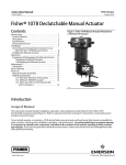
Instruction Manual
1080 Manual Actuator
D500236X012
October 2012
Fisherr 1080 Declutchable Manual Actuator
Contents
Introduction . . . . . . . . . . . . . . . . . . . . . . . . . . . . . . . . . 1
Scope of Manual . . . . . . . . . . . . . . . . . . . . . . . . . . . . . 1
Description . . . . . . . . . . . . . . . . . . . . . . . . . . . . . . . . . 2
Specifications . . . . . . . . . . . . . . . . . . . . . . . . . . . . . . . 2
Educational Services . . . . . . . . . . . . . . . . . . . . . . . . . 2
Installation . . . . . . . . . . . . . . . . . . . . . . . . . . . . . . . . . . 4
Installing the Manual Actuator . . . . . . . . . . . . . . . . . 4
Operation . . . . . . . . . . . . . . . . . . . . . . . . . . . . . . . . . . . 5
Engaging the Manual Actuator . . . . . . . . . . . . . . . . . 6
Disengaging the Manual Actuator . . . . . . . . . . . . . . 7
Maintenance . . . . . . . . . . . . . . . . . . . . . . . . . . . . . . . . . 7
Lubrication . . . . . . . . . . . . . . . . . . . . . . . . . . . . . . . . . 8
Parts Ordering . . . . . . . . . . . . . . . . . . . . . . . . . . . . . . . 11
Figure 1. Fisher 1080 Manual Actuator Mounted on a
1035/El-O-Matic Actuator
W9256
Introduction
Scope of Manual
This instruction manual includes installation, operation, and maintenance information for the Fisher 1080
Declutchable Manual Actuator. Refer to separate instruction manuals for instructions covering the 1035/El-O-Matic
actuator and the control valve.
Do not install, operate, or maintain a 1080 manual actuator without being fully trained and qualified in valve, actuator,
and accessory installation, operation, and maintenance. To avoid personal injury or property damage, it is important
to carefully read, understand, and follow all the contents of this manual, including all safety cautions and warnings. If
you have any questions about these instructions, contact your Emerson Process Management sales office before
proceeding.
www.Fisher.com
Instruction Manual
1080 Manual Actuator
October 2012
D500236X012
Table 1. Specifications
Available Configurations
Direct acting; see Handwheel Rotation
Manual Actuator Sizes
See table 2
Power Actuator Compatibility
Compatible with Fisher 1035 actuator;
see table 2
Maximum Torque Output
See table 2
Wheel-Rim Force
handwheel opposite the actuator supply connections
(see figure 2). Right hand or left hand mounting is
specified when ordered. Mounting position 1 is
standard.
Approximate Weight without Handwheel
Size AAA: 5.4 kg (12 lb)
Size AA: 10 kg (22 lb)
Size A: 14 kg (31 lb)
Size B: 22 kg (49 lb)
Size C: 34 kg (76 lb)
Size D: 52 kg(115 lb)
Size F: 68 kg (150 lb)
See table 2
Handwheel Rotation
Clockwise handwheel rotation closes valve (produces
clockwise valve shaft rotation)
Mounting Positions
Standard mounting is with the input shaft
perpendicular to the 1035 piston travel and the
Handwheel Weight
8-inch: 2.0 kg (4.50 lb)
12-inch: 4.0 kg (8.75 lb)
16-inch: 6.8 kg (15.00 lb)
24-inch: 5.4 kg (12.00 lb)
30-inch: 6.8 kg (15.00 lb)
36-inch: 7.8 kg (17.25 lb)
Description
The 1080 manual actuator, shown in figure 1, is a declutchable unit for manual operation of Fisher A41 and A31A
Cryogenic control valves that use a 1035 power actuator. The 1080 manual actuator mounts directly on the 1035
actuator. It can be engaged to allow manual operation of the valve when the power actuator is not in use or
disengaged to allow automatic operation of the valve by the power actuator. The mechanism used allows manual
actuator engagement at any point of power actuator rotation.
Specifications
The 1080 manual actuator specifications are given in table 1.
Educational Services
For information on available courses for 1080 manual actuators, as well as a variety of other products, contact:
Emerson Process Management
Educational Services, Registration
P.O. Box 190; 301 S. 1st Ave.
Marshalltown, IA 50158-2823
Phone: 800-338-8158 or
Phone: 641-754-3771
FAX: 641-754-3431
e-mail: [email protected]
2
Instruction Manual
1080 Manual Actuator
D500236X012
October 2012
Figure 2. Fisher 1080 Actuator Mounting Positions
1080 HANDWHEEL
FLOW DIRECTION
FOR LEFT HAND
MOUNTING
FLOW DIRECTION
FOR RIGHT HAND
MOUNTING
1080
HANDWHEEL
1035
PRESSURE PORTS
FLOW DIRECTION
FOR RIGHT HAND
MOUNTING
FLOW DIRECTION
FOR LEFT HAND
MOUNTING
1035 PRESSURE PORTS
FOR USE WITH 1035 ACTUATOR SIZES E25 THRU E350 & P4000
NOT AVAILABLE FOR 1035 ACTUATOR SIZES E600 THRU E1600 & P2500
FOR USE WITH 1035 ACTUATOR ALL SIZES
MOUNTING POSITION 1
(STANDARD)
MOUNTING POSITION 2
1035 PRESSURE PORTS
FLOW DIRECTION
FOR LEFT HAND
MOUNTING
FLOW DIRECTION
FOR RIGHT HAND
MOUNTING
1080 HANDWHEEL
FOR USE WITH 1035 ACTUATOR ALL SIZES
MOUNTING POSITION 3
FLOW DIRECTION
FOR RIGHT HAND
MOUNTING
FLOW DIRECTION
FOR LEFT HAND
MOUNTING
1080
HANDWHEEL
1035
PRESSURE PORTS
FOR USE WITH 1035 ACTUATOR SIZES E25 THRU E350 & P4000
NOT AVAILABLE FOR 1035 ACTUATOR SIZES E600 THRU E1600 & P2500
MOUNTING POSITION 4
NOTE:
RIGHT AND LEFT HAND MOUNTING IS BASED ON THE A41 VALVE DRIVE SHAFT BEING MOUNTED IN THE RECOMMENDED HORIZONTAL POSITION.
75B0768
B2702
3
1080 Manual Actuator
October 2012
Instruction Manual
D500236X012
Installation
The 1080 manual actuator is normally shipped mounted between the A31A Cryogenic or A41 valve assembly and the
1035 actuator. If the manual actuator is shipped separately for installation on the 1035 actuator, or if the manual
actuator was removed for maintenance, mount the manual actuator by following the instructions in this section.
Field conversion of the 1035 actuator for use with the 1080 manual actuator requires fastening an adaptor plate,
included with the manual actuator, to the 1035 actuator. The 1080 actuator is installed between the valve and the
1035 actuator.
Figure 2 shows the manual actuator mounting positions. Positions 1 and 3 are possible with all sizes of the 1035.
Positions 2 and 4 are only possible for 1035 sizes E25 through E350 and P4000. Fasten the adaptor plate to the power
actuator with the mounting bolts provided with the manual actuator. Use the torque values given in table 3.
Installing the Manual Actuator
If you purchased the 1080 actuator as part of a valve and power actuator assembly, step 13 is the only step you will
need to perform in the following procedures. If you purchased the 1080 actuator separately, perform all the steps and
read all warnings and cautions below.
WARNING
Refer to the WARNING at the beginning of the Maintenance section in this instruction manual.
1. Isolate the control valve from the line pressure, release pressure from both sides of the valve body, and drain the
process media from both sides of the valve. Also shut off all pressure lines to the power actuator and release all
pressure from the power actuator. Use lock-out procedures to be sure that the above measures stay in effect while
you work on the equipment.
2. For spring-return power actuators, allow the power actuator to remain in the position where the spring is relaxed.
For double-acting power actuators, apply supply pressure as appropriate to position the valve disc in either the
open or closed position.
3. Note whether the valve disc is in the open or closed position.
4. Engage the handwheel on the manual actuator. See the Engaging and Disengaging the Manual Actuator section in
this manual for instructions.
5. If using position 1 or 3 from figure 2, rotate the handwheel to line up the index mark on the top of the manual
actuator shaft and the drive shaft on the top of the power actuator. If using position 2 or 4 from figure 2, the index
mark on top of the power actuator input drive on the 1080 must be perpendicular to the face of the valve disc and
the slot in the top of the power actuator shaft (see figure 3).
6. Determine the correct relative positions of the power and manual actuators (see figure 2).
7. Remove the adaptor plate on the top of the gear box (see figure 3).
8. Attach the adaptor plate to the bottom of the power actuator with bolts furnished with the adaptor plate.
9. Slide the power actuator input drive into the power actuator (see figure 3).
10. Rotate either the manual actuator or the power actuator slightly so that the mounting holes on the manual
actuator align with the mounting holes in the mounting plate on the power actuator.
11. Fasten the manual actuator to the mounting plate with the bolts, washers and nuts provided (see table 3).
4
Instruction Manual
1080 Manual Actuator
D500236X012
October 2012
12. Install the power actuator and manual actuator assembly on the valve as described in the installation section of
the power actuator instruction manual. Remember the positions noted in steps 3 and 6, because you will need
them when aligning the drive shaft on the top of the power actuator and the valve shaft.
CAUTION
Undertravel or overtravel of the valve disc, especially at the closed position, may result in poor valve performance and/or
damage to the equipment. Make certain that the power actuator travel stops are properly set before installing the valve.
Refer to the instruction manuals for the power actuator for information about setting travel stops.
Note
When the 1080 actuator is mounted on a P Series 1035 power actuator, the travel stops are set in the 1080 actuator and a Limit
Stop Plate is not used.
13. Make certain that the power actuator travel stops have been properly set.
For the E series 1035 actuator travel stops, the travel stop adjustments are made in the power actuator.
For the P series, you will need to adjust the travel stops on the side of the gearbox to the left of the handwheel.
The adjusting travel stops procedure is in the 1035/El-O-Matic Rack-and-Pinion Rotary Actuator Instruction Manual,
D500243X012.
14. Install the valve in the line using the instructions in the valve instruction manual.
Operation
After the actuator and control valve assembly are installed, the manual actuator is ready for operation.
WARNING
Applying too much torque to the actuator and valve parts could cause damage to the parts and result in loss of control of
key internal valve components (e.g. disc or ball). This loss of control may result in personal injury due to a sudden increase
or decrease of pressure within -- or release of pressure from -- the pipeline. To avoid such damage or personal injury, do not
exceed the wheel rim force listed in table 2. Also, do not use wrenches or other devices on the handwheel or handwheel
shaft to increase operating force.
If the force required to rotate the handwheel exceeds the wheel-rim force listed in table 2, refer to the Maintenance
procedures.
5
Instruction Manual
1080 Manual Actuator
October 2012
D500236X012
Table 2. Actuator Size Selection and Specifications(1)
ACTUATOR
SIZE
1035
ACTUATOR
SIZE
AAA/S1
E25
E40
E65
E100
AAA/S2
AAA/S3
GEAR
RATIO
NUMBER OF
TURNS TO
CLOSE
HANDWHEEL
DIAMETER
mm
Inches
1035 TORQUE(3)
NSm
NSm
lbSin
31
274
49
11
58
89
132
513
788
1,168
93
147
218
21
33
49
289
502
2,558
4,443
222
387
50
87
lbSin
24:1
6
203
8
271
2,400
8.5
305
12
542
4,800
610
24
AA/S4
E200
E350
34:1
A/S4
E600
32:1
8
B/S5
E950
40:1
10
C/S6
E1600
54:1
13.5
762
D/SQ3
P2500
64:1
16
F/SQ4
P4000
282:1
70.5
WHEEL RIM FORCE
FOR MAXIMUM
TORQUE(4)
N
lbf
1080 MAXIMUM
TORQUE(2)
926
8,200
866
7,550
276
62
1,356
12,000
1,290
11,300
271
61
30
2,034
18,000
2,140
18,600
298
67
914
36
3,390
30,000
3,377
29,891
383
86
406
16
6,779
60,000
5,701
50,458
334
75
1. Only the 1080/1035 combinations shown are available.
2. Maximum torque output of the 1080 actuator only.
3. Torque output of the 1035 actuator at 100 psig and required 1080 torque output for use with the 1035.
4. Amount of force necessary at rim of the handwheel to match torque output of the 1035 at 100 psig.
Engaging and Disengaging the Manual Actuator
Engaging the Manual Actuator
1. Engage the manual actuator before venting the power actuator loading pressure. Releasing the air pressure prior to
engaging could result in undesirable valve rotation.
WARNING
Undesirable valve rotation or loss of control of key internal valve components (e.g. disc/ball), may result in personal injury
due to a sudden increase or decrease of pressure within - or release of pressure from - the pipeline.
2. Pull the ring on the detent mechanism to unlock the lever. At the same time, move the lever into the engaged
position until it is against the stop pin and locked in position by the detent mechanism. See figure 3.
3. If the lever sticks midway, turn the handwheel 1/3 turn (2 full turns for units with additional gearbox between the
handwheel and lever). Then try the detent lever again. Repeat this step as necessary, turning the handwheel in the
same direction, until the lever moves freely (see figure 4). The reason the lever may stick is that the worm is not in
proper alignment with the gear (see figure 4). Rotation of the worm will allow for proper alignment. Excessive force
should not be required.
4. Shut off supply pressure to the power actuator and bleed off or equalize pressure in the cylinders. If applicable,
open the power actuator bypass valve.
Note
If the loading pressure in the power actuator has already been released, you will not need to use the optional bypass relief valve.
6
Instruction Manual
D500236X012
1080 Manual Actuator
October 2012
Disengaging the Manual Actuator
WARNING
Disengaging the manual actuator when forces, such as spring compression, cylinder pressure, and dynamic torque, are
present may cause sudden, extreme movement of all control valve components. Disengaging the lever with excessive force
can result in damage to equipment and violent disturbance of the process.
Damage to equipment resulting in loss of control of internal valve components (e.g. disc/ball) - or violent disturbance of
the process may result in personal injury due to a sudden increase or decrease of pressure within - or release of pressure
from - the pipeline.
Before disengaging the manual actuator, take appropriate steps to ensure that the return to automatic operation will not
result in an extreme repositioning of control valve components. Procedures to determine approximate system balance are
given in the following steps.
1. Approximate system balance should be achieved, before disengaging the manual actuator. The system is in balance
when the actual valve disc position is approximately the same as the position requested by the automatic control
system. Under balanced system conditions, the manual actuator disengaging lever moves freely without use of
excessive force.
If after releasing the detent mechanism, the lever does not move freely toward the disengaged position, some system
force is causing an imbalance. A forced return to automatic operation under these conditions can cause serious
damage to the equipment and violent disturbance of the process.
2. If possible, determine whether the automatic control system is tending to open or close the valve disc, and rotate
the handwheel in the appropriate direction until the lever can be easily moved by hand. As an alternate approach,
local manipulation of the supply pressure to the power actuator may bring the set point of the automatic system
closer to the actual valve disc position.
3. If a smooth transition from manual to automatic operation cannot be ensured, isolate the valve from the process.
On Spring Return actuators, position the manual actuator and the disc to the spring fail open or close (whichever is
applicable) end of travel so that no position changes will happen when supply pressure is applied to the power
actuator. On double-acting actuators, this positioning will not be necessary.
4. Pull the ring on the detent mechanism to unlock the lever. Push the lever into the disengaged position until it is
against the stop pin and locked in position by the detent mechanism.
5. Close the bypass valve, if needed, and return supply pressure to the power actuator.
Maintenance
WARNING
Avoid personal injury from sudden release of process pressure or bursting of parts. Before performing any maintenance
operations:
D Do not remove the actuator from the valve while the valve is still pressurized.
D Always wear protective gloves, clothing, and eyewear when performing any maintenance operations to avoid personal
injury.
D Disconnect any operating lines providing air pressure, electric power, or a control signal to the power actuator. Be sure
the actuator cannot suddenly open or close the valve.
D Use bypass valves or completely shut off the process to isolate the valve from process pressure. Relieve process pressure
from both sides of the valve. Drain the process media from both sides of the valve.
7
1080 Manual Actuator
October 2012
Instruction Manual
D500236X012
D Vent the power actuator loading pressure and relieve any actuator spring precompression. If using a Spring Return
actuator, first check to make sure the valve has been moved to the fail safe position to prevent unexpected actuator
movement.
D Use lock-out procedures to be sure that the above measures stay in effect while you work on the equipment.
D The valve packing box may contain process fluids that are pressurized, even when the valve has been removed from the
pipeline. Process fluids may spray out under pressure when removing the packing hardware or packing rings, or when
loosening the packing box pipe plug.
D Check with your process or safety engineer for any additional measures that must be taken to protect against process
media.
If the force required to rotate the handwheel exceeds the wheel-rim force listed in table 2 check for the following
conditions:
D Insufficient lubrication
D Seized actuator parts
D Excessive pressure drop across the valve, or
D Obstruction to the valve disc rotation.
If the manual actuator does not seem to control the process fluid, the worm or drive sleeve gear teeth may be broken,
the handwheel pin may be sheared, or the power actuator or internal valve parts may be broken.
Refer to the power actuator and valve instruction manuals if power actuator or valve maintenance is needed.
Lubrication
The interior parts of the 1080 manual actuator should be lubricated on a regular schedule with a quality gear lubricant.
The interior parts should also be lubricated whenever difficulty in handwheel rotation indicates a need for lubrication.
WARNING
Before performing any of these lubrication procedures, observe the steps in the WARNING at the beginning of the
Maintenance section.
1. Isolate the control valve from the line pressure, release pressure from both sides of the valve body, and drain the
process media from both sides of the valve. If using a power actuator, also shut off all pressure lines to the power
actuator, release all pressure from the actuator. Use lock-out procedures to be sure that the above measures stay in
effect while you work on the equipment.
2. Remove the bolts that secure the power actuator to the manual actuator adaptor plate and remove the power
actuator.
3. Remove the cap screws that secure the gearbox lid and remove the gearbox lid.
4. Coat the worm, the drive sleeve gear teeth, and the bearing surfaces of the gearbox housing and worm with a
quality gear lubricant.
5. Replace the cover plate and cap screws using the bolt torques listed in table 5.
6. Replace the power actuator on the manual actuator. Fasten the manual actuator to the adaptor plate using the
torque values in table 3.
8
Instruction Manual
1080 Manual Actuator
D500236X012
October 2012
Table 3. Fisher1080 Adaptor Plate to Gearbox
1080 Actuator
Bolt Size
Bolt Torque NSm
Bolt Torque lbSf
AAA/S1
3/8
39
29
AAA/S2
3/8
39
29
AAA/S3
3/8
39
29
AA/S4
1/2
91
67
A/S4
5/8
163
120
B/S5
5/8
163
120
C/S6
3/4
258
190
D/SQ3
5/8
163
120
F/SQ4
5/8
163
120
Bolt Torque lbSf
Table 4. Fisher 1080 Mounting Bracket to 1035 Actuator
1080 Actuator
Bolt Size
Bolt Torque NSm
AAA/S1
1/4
11.3
8.3
AAA/S2
5/16
22.4
16.5
AAA/S3
5/16
22.4
16.5
AA/S4
3/8
39.3
29
A/S4
1/2
90.8
67
B/S5
5/8
122
90
C/S6
3/4
203
150
D/SQ3
3/4
5/8
203
122
150
90
F/SQ4
3/4
5/8
203
122
150
90
1080 Actuator
Bolt Size
Bolt Torque NSm
Bolt Torque lbSf
AAA/S1
5/16
31.2
23.0
AAA/S2
5/16
31.2
23.0
AAA/S3
5/16
31.2
23.0
AA/S4
3/8
56.3
41.5
A/S4
1/2
138
102
B/S5
5/8
277
204
C/S6
3/4
494
364
D/SQ3
5/8
277
204
F/SQ4
3/4
494
364
Table 5. Fisher 1080 Gearbox Lid
9
Instruction Manual
1080 Manual Actuator
October 2012
D500236X012
Figure 3. Typical Fisher 1080 Assembly
POWER ACTUATOR
INPUT DRIVE
LEVER
INDEX
MARK
GEAR BOX
DETENT PIN
HANDWHEEL
24B0392-A
A7115-1
Figure 4. Worm Gear Mechanism
LEVER
HANDWHEEL
SHAFT
DETENT PIN
ENGAGED
75B0745-A
A7235
10
DISENGAGED
Instruction Manual
D500236X012
1080 Manual Actuator
October 2012
Parts Ordering
When corresponding with your Emerson Process Management sales office, indicate the size of the 1080 actuator. The
size is stamped on the gearbox. Also, give the serial number of the unit, which is shown on a tag attached to the
manual actuator.
WARNING
Use only genuine Fisher replacement parts. Components that are not supplied by Emerson Process Management should
not, under any circumstances, be used in any Fisher valve, because they may void your warranty, might adversely affect the
performance of the valve, and could cause personal injury and property damage.
11
1080 Manual Actuator
October 2012
Instruction Manual
D500236X012
Neither Emerson, Emerson Process Management, nor any of their affiliated entities assumes responsibility for the selection, use or maintenance
of any product. Responsibility for proper selection, use, and maintenance of any product remains solely with the purchaser and end user.
Fisher is a mark owned by one of the companies in the Emerson Process Management business unit of Emerson Electric Co. Emerson Process Management,
Emerson, and the Emerson logo are trademarks and service marks of Emerson Electric Co. All other marks are the property of their respective owners.
The contents of this publication are presented for informational purposes only, and while every effort has been made to ensure their accuracy, they are not
to be construed as warranties or guarantees, express or implied, regarding the products or services described herein or their use or applicability. All sales are
governed by our terms and conditions, which are available upon request. We reserve the right to modify or improve the designs or specifications of such
products at any time without notice.
Emerson Process Management
Marshalltown, Iowa 50158 USA
Sorocaba, 18087 Brazil
Chatham, Kent ME4 4QZ UK
Dubai, United Arab Emirates
Singapore 128461 Singapore
www.Fisher.com
12
E 1998, 2012 Fisher Controls International LLC. All rights reserved.