1
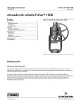
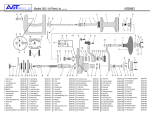
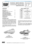
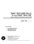
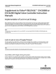
Instruction Manual
1008 Handwheel Actuator
D100318X012
May 2011
Fisherr 1008 Handwheel Actuator
Contents
Introduction . . . . . . . . . . . . . . . . . . . . . . . . . . . . . . . . . . .
Scope of Manual . . . . . . . . . . . . . . . . . . . . . . . . . . . . .
Description . . . . . . . . . . . . . . . . . . . . . . . . . . . . . . . . .
Specifications . . . . . . . . . . . . . . . . . . . . . . . . . . . . . . .
Installation . . . . . . . . . . . . . . . . . . . . . . . . . . . . . . . . . . . .
Actuator Mounting . . . . . . . . . . . . . . . . . . . . . . . . . . .
Position Indicator Mounting . . . . . . . . . . . . . . . . . . .
Maintenance . . . . . . . . . . . . . . . . . . . . . . . . . . . . . . . . . .
Lubrication . . . . . . . . . . . . . . . . . . . . . . . . . . . . . . . . .
Disassembly . . . . . . . . . . . . . . . . . . . . . . . . . . . . . . . .
Assembly . . . . . . . . . . . . . . . . . . . . . . . . . . . . . . . . . . .
Reversing Handwheels . . . . . . . . . . . . . . . . . . . . . . . .
Parts Ordering . . . . . . . . . . . . . . . . . . . . . . . . . . . . . . . . .
Parts List . . . . . . . . . . . . . . . . . . . . . . . . . . . . . . . . . . . . . .
Figure 1. Fisher 1008 Handwheel Actuator
1
1
2
2
2
3
3
4
4
4
6
8
8
9
W0590‐1
Introduction
Scope of Manual
This instruction manual presents principle of operation, installation, maintenance, and parts list for the Fisher 1008
handwheel actuator (figure 1). Refer to separate instruction manuals for information about other equipment and
accessories used with these actuators.
Do not install, operate, or maintain a 1008 handwheel actuator without being fully trained and qualified in valve,
actuator, and accessory installation, operation, and maintenance. To avoid personal injury or property damage, it is
important to carefully read, understand, and follow all the contents of this manual, including all safety cautions and
warnings. If you have any questions about these instructions, contact your Emerson Process Management sales office
before proceeding.
www.Fisher.com
Instruction Manual
1008 Handwheel Actuator
May 2011
D100318X012
Table 1. Specifications
SIZE
YOKE BOSS DIAMETER
STEM DIAMETER
MAXIMUM STEM LOAD
MAXIMUM TRAVEL
APPROXIMATE WEIGHT
mm
Inch
mm
Inch
N
lbs
mm
Inch
kg
lbs
30
54
2‐1/8
10
3/8
7340
1650(1)
19
0.75
6.8
15
40
71
2‐13/16
13
1/2
13122
2950(1)
51
2
15.9
35
50
90
3‐9/16
19
3/4
29581
6650(1)
102
4
20.4
45
25
1
50042
11250(1)
32
1‐1/4
75620
17000(1,2)
76(3)
3(3)
45.4
100
102
4
68.0
150
80
100
127
5
127
5
32
1‐1/4
75620
17000(1,2)
178
7
51
2
251004
56000(1,2)
1. For S31600 (316 stainless steel) stems at 38_C (100_F).
2. Actuator limit.
3. Alternate 102 mm (4 inch) travel construction is available.
Description
The 1008 is a handwheel actuator for processes requiring a throttling valve that can be manually operated and set.
The 1008 handwheel actuator is available in sizes 30, 40, 50, 80, and 100, and can be mounted on easy‐et valves.
The 1008 handwheel actuator converts rotary motion of the handwheel to linear motion of the valve plug stem.
Because the stem does not revolve, the valve plug contacts the same seating surface with each stroke. Sizes 40, 50,
80, and 100 include two thrust bearings to make rotation easier.
Turn the handwheel counterclockwise to open the valve regardless of valve plug action. All sizes of the 1008
handwheel actuator except size 100 are reversible following the Reversing Handwheel procedures in this instruction
manual.
Specifications
Refer to table 1 for 1008 handwheel actuator specifications. Refer to the actuator nameplate for information about a
specific actuator.
Installation
WARNING
Always wear protective gloves, clothing, and eyewear when performing any installation operations to avoid personal
injury.
Check with your process or safety engineer for any additional measures that must be taken to protect against process
media.
If installing into an existing application, also refer to the WARNING at the beginning of the Maintenance section in this
instruction manual.
The 1008 handwheel actuator can be installed horizontally, vertically, or at any orientation in between. However, if
supplied with a Tejax position indicator (see figure 6), the actuator must be installed in a horizontal position.
When an actuator and valve body are shipped together as a control valve assembly, the actuator is normally mounted
on the valve. Follow the valve body instructions when installing the control valve in the pipeline. If the actuator is
2
Instruction Manual
1008 Handwheel Actuator
D100318X012
May 2011
shipped separately or if it is necessary to mount the actuator on the valve, perform the Actuator Mounting
procedures.
Actuator Mounting
Key numbers refer to figure 2 for size 30, figure 3 for sizes 40 and 50, figure 4 for size 80 or figure 5 for size 100.
1. Place the actuator on the body bonnet and tighten the yoke locknut or the actuator mounting hex nuts.
2. Ensure the valve plug is on its seat.
3. Adjust the travel indicator scale (key 27) so that the two screws (key 19) are centered in the slots.
4. Screw the hex nuts (key 29) onto the valve plug stem and place the travel indicator disk (key 20) onto the stem
above the hex nuts. Adjust the nuts until the travel indicator disk (key 20) points to the closed position on the scale.
5. Temporarily connect the valve plug stem to the stem connector assembly (key 24) and tighten the cap screws into
the stem connector.
6. Use the handwheel (key 28) to move the valve plug into the fully open position, as indicated by the travel indicator
disk (key 20) on the travel indicator scale (key 27).
7. Remove the stem connector assembly (key 24).
8. Size 30: Turn the handwheel (key 28) counterclockwise until the stem connector assembly (key 24) almost touches
the top of the yoke;
Sizes 40, 50, and 80: Turn the handwheel (key 28) counterclockwise as far as it will go;
Size 100: Turn the handwheel (key 28) counterclockwise (for push‐down‐to‐close valves) or clockwise (for
push‐down‐to‐open valves) as far as it will go.
CAUTION
Incomplete engagement of both valve stem and stem screw assembly (key 38) or size 100 power screw (key 5) in the stem
connector can result in stripped threads or improper operation. Be sure that the length of each stem clamped in the stem
connector is equal to or greater than the diameter of that stem.
9. Connect the valve plug stem to the stem connector assembly (key 24). Ensure that the bottom of the stem
connector is touching or nearly touching the travel indicator disk (key 20). Tighten the stem connector (key 24) cap
screws and lock the hex nuts (key 29) against the travel indicator disk (key 20) and stem connector.
10. Rotate the handwheel until the valve plug seats. Adjust the travel indicator scale (key 27) with two screws (key 19)
so that the travel indicator disk (key 20) points to the closed position on the scale. Tighten the two screws.
Position Indicator Mounting
The Tejax position indicator is available on 1008 handwheel actuators, sizes 30, 40, and 50. It must be mounted in a
horizontal position to function correctly. To set the position indicator:
1. Seat the valve plug.
2. Loosen the four screws holding the dial indicating unit in place.
3. Turn the dial until both hands are at the “Shut” (Zero) position.
4. Tighten the four screws.
The long pointer indicates fractions of a turn; the small pointer counts the number of full turns. The position indicator
requires no lubrication.
3
1008 Handwheel Actuator
Instruction Manual
May 2011
D100318X012
Maintenance
Actuator parts are subject to normal wear and must be inspected and replaced when necessary. The frequency of
inspection and replacement depends on the severity of service conditions.
WARNING
Avoid personal injury from sudden release of process pressure. Before performing any maintenance operations:
D Do not remove the actuator from the valve while the valve is still pressurized.
D Always wear protective gloves, clothing, and eyewear when performing any maintenance operations to avoid personal
injury.
D Use bypass valves or completely shut off the process to isolate the valve from process pressure. Relieve process pressure
on both sides of the valve. Drain the process media from both sides of the valve.
D Use lock‐out procedures to be sure that the above measures stay in effect while you work on the equipment.
D The valve packing box may contain process fluids that are pressurized, even when the valve has been removed from the
pipeline. Process fluids may spray out under pressure when removing the packing hardware or packing rings, or when
loosening the packing box pipe plug.
D Check with your process or safety engineer for any additional measures that must be taken to protect against process
media.
Key numbers refer to figure 2 for size 30, figure 3 for sizes 40 and 50, figure 4 for size 80 or figure 5 for size 100.
Lubrication
The interior parts of a 1008 handwheel actuator should be lubricated on a regular schedule with a quality gear
lubricant. The interior parts should also be lubricated whenever handwheel rotation becomes difficult.
Disassembly
Parts are subject to normal wear and must be inspected periodically. The following procedure describes actuator
disassembly for general inspection and replacement.
For Size 30:
1. Remove the stem connector assembly (key 24).
2. Unscrew the set screw (key 13) from the yoke (key 26) and remove the steel balls (key 33) through the threaded
hole.
Note
Be careful not to lose the ball (key 33) and spring (key 34) as the handwheel is removed.
3. Remove the handwheel (key 28) and stem screw assembly (key 38) from the yoke (key 26).
4
Instruction Manual
1008 Handwheel Actuator
D100318X012
May 2011
4. Unscrew the handwheel (key 28) from the stem screw assembly (key 38).
For Sizes 40 & 50:
1. Remove the stem connector assembly (key 24).
2. Unscrew the hex nut (key 14) and remove the washer (key 41) and lockwasher (key 42).
Note
Be careful not to lose the ball (key 33) and spring (key 34) as the handwheel is removed.
3. Remove the handwheel (key 28) from the stem screw assembly (key 38).
4. Loosen the set screw (key 13) and unscrew the bearing retainer (key 44).
5. Remove the stem screw assembly (key 38), thrust bearings (key 2), and nut (key 43) from the yoke (key 26).
6. Remove the nut from the stem screw assembly (key 38) to reach the remainder of the parts.
For Size 80:
1. Remove the stem connector assembly (key 24).
2. Unscrew the cap screws (key 12) and remove the gear case cover (key 11).
3. Unscrew the two socket head cap screws (key 37) and remove the retaining flange (key 35).
4. Remove the bearing and gear retainer (key 4) and the stem screw assembly (key 38).
5. Remove the thrust bearings (key 2) and worm gear (key 3) from the stem screw assembly (key 38).
Note
Be careful not to lose the ball (key 33) and spring (key 34) as the handwheel is removed.
6. To remove the worm shaft (key 9):
a. Remove the set screw from the handwheel cap (key 32).
b. Unscrew the handwheel cap and remove the handwheel (key 28).
c. Loosen the front (nearest to the threaded end of the worm shaft) set screw (key 10) and unscrew the front worm
retainer (key 7).
d. Remove the ball bearing (key 8) and the worm shaft.
For Size 100:
1. Remove the stem connector assembly (key 24).
2. Unscrew the cap screws (key 12) and remove the gear case cover (key 11).
3. Remove the bearing and gear retainer (key 4) and the stem screw assembly (key 38).
4. Remove the thrust bearings (key 2) and worm gear (key 3) from the stem screw assembly (key 38).
5
1008 Handwheel Actuator
Instruction Manual
May 2011
D100318X012
5. To remove the worm shaft (key 9):
a. Remove the retaining ring (key 17).
b. Loosen the set screw (key 10) found on the handwheel (key 28) hub.
c. Remove the handwheel (key 28).
d. Loosen the set screw (key 10) and remove the front (nearest to the threaded end of the worm shaft) worm
retainer (key 7), worm shaft (key 9), and front ball bearing (key 8).
Assembly
For Size 30:
1. Replace the spring (key 34) and ball (key 33) in the yoke (key 26).
2. Screw the handwheel (key 28) on the stem screw assembly (key 38).
3. Position the grooves in the handwheel (key 28) and yoke (key 26) to mate, then replace the steel balls (key 33) in
the yoke through the threaded hole.
4. Replace the set screw (key 13).
5. Refer to the Installation procedures for instructions on connecting the valve plug stem to the actuator stem screw
assembly (key 38).
For Sizes 40 & 50:
1. Replace the thrust bearings (key 2) and bearing seat (key 45) on the stem screw assembly (key 38). Screw the nut
(key 43) on the stem screw assembly.
Note
Verify that the key (key 16) fits into the slot milled in the yoke (key 26) before reassembly.
2. Place the stem screw assembly (key 38) in the yoke (key 26).
3. Replace the bearing retainer (key 44), tightening so that the thrust bearings (key 2) move freely, then tighten the
set screw (key 13).
4. Place the ball (key 33) in one of the indentations on the yoke, then place the handwheel (key 28) with the spring
(key 34) over the ball.
5. Replace the lock washer (key 42) and washer (key 41) on the stem screw assembly (key 38) and tighten the hex nut
(key 14).
6. Refer to the Installation procedures for instructions on connecting the valve plug stem to the actuator stem screw
assembly (key 38).
For Size 80:
1. If the worm shaft (key 9) was removed during disassembly:
a. Replace the worm shaft with the ball bearing (key 8) and the front worm retainer (key 7).
b. Adjust the worm retainer to eliminate end play (movement of the worm shaft along its axis) while allowing
adequate movement.
6
Instruction Manual
1008 Handwheel Actuator
D100318X012
May 2011
c. Tighten the set screw (key 10) on the front retainer.
2. Replace the ball (key 33), handwheel (key 28), and handwheel cap (key 32), then tighten the set screw in the
handwheel cap.
3. Replace one of the thrust bearings (key 2) in the gear case (key 1) making sure that the bearing race with the
smaller inside diameter is adjacent to the worm gear web.
4. Screw the worm gear (key 3) on the stem screw assembly (key 38) and place them in the gear case (key 1).
5. Install the other thrust bearing (key 2) on the worm gear (key 3), making sure that the bearing race with the smaller
inside diameter is adjacent to the worm gear web.
6. Replace the bearing and gear retainer (key 4).
7. Install the retaining flange (key 35) making sure that the key (key 36) fits in the slot on the retaining flange.
8. Coat the threads on the six set screws (key 13) with a hard‐setting sealant. Adjust the six set screws to eliminate
end play (movement along the axis of the stem screw assembly) in the thrust bearings, while allowing adequate
movement.
9. Replace the gear case cover (key 11) and cap screws (key 12).
10. Replace the stem connector assembly (key 24).
11. Refer to the Installation procedures for instructions on connecting the valve plug stem to the actuator stem screw
assembly (key 38).
For Size 100:
1. If the worm shaft (key 9) was removed during disassembly:
a. Replace the worm shaft with the ball bearing (key 8) and the front worm retainer (key 7).
b. Adjust the worm retainer to eliminate end play (movement of the worm shaft along its axis) while allowing
adequate movement.
c. Tighten the set screw (key 10) on the front retainer.
2. Replace the key (key 16), handwheel (key 28), and retaining ring (key 17), then tighten the set screw in the hub of
the handwheel.
3. Replace one of the thrust bearings (key 2) in the gear case (key 1) making sure that the bearing race with the
smaller inside diameter is adjacent to the worm gear web.
4. Screw the worm gear (key 3) on the stem screw assembly (key 38) and place them in the gear case (key 1).
5. Install the other thrust bearing (key 2) on the worm gear (key 3), making sure that the bearing race with the smaller
inside diameter is adjacent to the worm gear web.
6. Replace the bearing and gear retainer (key 4).
7. Replace the gear case cover (key 11) and fasten with the cap screws (key 12).
8. Adjust the six set screws (key 13) to eliminate end play (movement along the axis of the stem screw assembly) in
the thrust bearings, while allowing adequate movement.
9. Replace the stem connector assembly (key 24).
10. Refer to the Installation procedures for instructions on connecting the valve plug stem to the actuator stem screw
assembly (key 38).
7
1008 Handwheel Actuator
Instruction Manual
May 2011
D100318X012
Reversing Handwheels
Refer to the previous Disassembly and Assembly sections in this manual for additional instructions, as needed.
To reverse 1008 handwheel actuators sizes 30, 40, or 50, substitute left‐ or right‐hand screw assemblies (key 38). The
standard size 100 is not reversible. To reverse size 80, refer to figure 4 while performing the following procedures:
1. Loosen the three set screws (key 10) in the gear case (key 1) and handwheel cap (key 32).
Note
Be careful not to lose the ball (key 33) and spring (key 34) as the handwheel is removed.
2. Unscrew the handwheel cap (key 32) and remove the handwheel (key 28).
3. Remove the front worm retainer (key 7), ball bearing (key 8), and worm shaft (key 9).
4. Remove the back worm retainer (key 6) and ball bearing (key 8).
5. Screw the back worm retainer (key 6) and ball bearing (key 8) into the opening in the gear case (key 1) where the
front worm retainer is located.
6. Replace the front worm retainer (key 7) and ball bearing (key 8).
7. Replace the spring (key 34) and ball (key 33), handwheel (key 28), and handwheel cap (key 32).
8. Tighten the three set screws (key 10) in the gear case (key 1) and handwheel cap (key 32).
Parts Ordering
Each actuator has a serial number stamped on the nameplate. Always mention this number when corresponding with
your Emerson Process Management sales office regarding technical information or replacement parts. Also, reference
the complete 11‐character part number of each needed part as found in the following Parts List.
WARNING
Use only genuine Fisher replacement parts. Components that are not supplied by Emerson Process Management should
not, under any circumstances, be used in any Fisher valve, because they may void your warranty, might adversely affect the
performance of the valve, and could cause personal injury and property damage.
Note
Neither Emerson, Emerson Process Management, nor any of their affiliated entities assumes responsibility for the selection, use, or
maintenance of any product. Responsibility for the selection, use, and maintenance of any product remains with the purchaser and
end user.
8
Instruction Manual
1008 Handwheel Actuator
D100318X012
Parts List
Note
Part numbers are shown for recommended spares only. For part
numbers not shown, contact your Emerson Process Management sales
office.
Key
Description
1
2
3
4
5
6
7
8
9
10
11
12
13
Gear Case
Bearing, steel (2req'd)
Worm Gear, bronze
Bearing & Gear Retainer, brass
Power Screw, steel (size 100)
Back Worm Retainer, steel (sizes 80 & 100)
Front Worm Retainer, steel (sizes 80 & 100)
Ball Bearing, steel (2req'd)
Worm Shaft, alloy steel
Set Screw, steel (3 req'd) (sizes 80 & 100)
Gear Case Cover, steel
Cap Screw, steel (8 req'd) (size 100)
Set Screw, steel
Size 30
Sizes 40 & 50
Size 80 (6 req'd)
Size 100 (6 req'd)
Hex Nut, steel
Size 30
Sizes 40 & 50
Size 100 (6 req'd)
Grease Fitting, steel (all sizes)
Key, stainless steel
Sizes 40 & 50
Size 100
Retaining Ring, steel (size 100)
Cap Screw, steel (8 req'd) (size 100)
Socket‐Head Cap Screw, steel (6 req'd) (size 80)
Screw, stainless steel (2req'd)
Travel Indicator Disk, stainless steel
14
15
16
17
18
18
19
20
May 2011
Key
Description
21
22
23
23
24
25
Cap Screw, steel (2req'd) (size 100)
Nameplate, stainless steel
Nameplate Screw, steel (2 req'd)
Drive Screw, SST (4 req'd)
Stem Connector Assembly, 416 stainless steel
Cap Screw, steel
Size 80 (2req'd)
Size 100 (4 req'd)
Yoke
Travel Indicator Scale, stainless steel
Handwheel
Hex Nut, steel (2 req'd)
Size 30 (1 each, full and jam)
Size 40
Size 50 (1 each, full and jam)
Size 80
Size 100
Hand Grip, steel (size 80)
Hand Grip Bolt, steel (size 80)
Handwheel Cap, cast iron (size 80)
Ball, steel
Size 30 (16 req'd)
Sizes 40 & 50 (1 req'd)
Size 80 (1 req'd)
Spring, plated steel
Retaining Flange, steel (size 80)
Key, steel (size 80)
Cap Screw, steel (size 80) (2 req'd)
Stem Screw Assembly, steel
Travel Stop, steel (size 80)
Machine Screw, plated steel (2 req'd) (size 80)
Washer, steel (sizes 40 & 50)
Lock Washer, steel (sizes 40 & 50)
Nut, stainless steel
Bearing Retainer, brass (sizes 40 & 50)
Bearing Seat, steel (sizes 40 & 50)
Twin Speed Nut, stainless steel
Tejax Indicator
Set Screw w/Set Screw Handwheel Lock, (not shown)
(sizes 40 & 50)
Cover, aluminum (size 30)
26
27
28
29
30
31
32
33
34
35
36
37
38
39
40
41
42
43
44
45
46
47
48
51
9
Instruction Manual
1008 Handwheel Actuator
May 2011
D100318X012
Figure 2. Fisher 1008 Handwheel Actuator Size 30
A
A
SECTION A‐A
PARTS NOT SHOWN 46, 50, AND 22
30A6973‐D
10
Instruction Manual
1008 Handwheel Actuator
D100318X012
May 2011
Figure 3. Fisher 1008 Handwheel Actuator Sizes 40 and 50
PARTS NOT SHOWN
KEY 22 & 23
30A6972‐A
11
1008 Handwheel Actuator
Instruction Manual
May 2011
D100318X012
Figure 4. Fisher 1008 Handwheel Actuator Size 80
COAT THREADS, KEY 13, WITH A
HARD‐SETTING SEALANT
30A6911‐A
12
Instruction Manual
D100318X012
1008 Handwheel Actuator
May 2011
Figure 5. Fisher 1008 Handwheel Actuator Size 100
50A2650‐B
13
1008 Handwheel Actuator
May 2011
D100318X012
Figure 6. Fisher 1008 Handwheel Actuator Sizes 40 and 50 with Tejax Position Indicator
40A6974‐A
14
Instruction Manual
Instruction Manual
D100318X012
1008 Handwheel Actuator
May 2011
15
1008 Handwheel Actuator
May 2011
Instruction Manual
D100318X012
Fisher and easy-e are marks owned by one of the companies in the Emerson Process Management business division of Emerson Electric Co. Emerson
Process Management, Emerson, and the Emerson logo are trademarks and service marks of Emerson Electric Co. All other marks are the property of their
respective owners.
The contents of this publication are presented for informational purposes only, and while every effort has been made to ensure their accuracy, they are not
to be construed as warranties or guarantees, express or implied, regarding the products or services described herein or their use or applicability. All sales
are governed by our terms and conditions, which are available upon request. We reserve the right to modify or improve the designs or specifications of
such products at any time without notice. Neither Emerson, Emerson Process Management, nor any of their affiliated entities assumes responsibility for the
selection, use or maintenance of any product. Responsibility for proper selection, use, and maintenance of any product remains solely with the purchaser
and end user.
Emerson Process Management
Marshalltown, Iowa 50158 USA
Sorocaba, 18087 Brazil
Chatham, Kent ME4 4QZ UK
Dubai, United Arab Emirates
Singapore 128461 Singapore
www.Fisher.com
16
EFisher
Controls International LLC 1990, 2011; All Rights Reserved