1
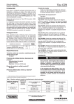
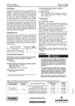
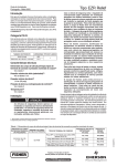
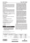
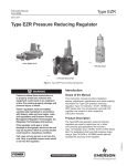
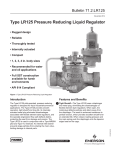
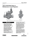
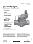
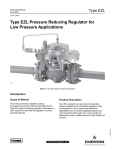
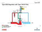
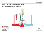
Installation Guide
English – May 2002
Type EZR
Introduction
This installation guide provides instructions for installation,
startup, and adjustment. To receive a copy of the instruction
manual,
contact
your
local
Fisher
Sales
Office or Sales Representative or view a copy at
www.FISHERregulators.com. For further information refer to:
Type EZR Instruction Manual, form 5468, D102600X012.
The Type EZR pilot-operated, pressure reducing regulators are used for natural gas, air, or other non-corrosive
gas applications and include a Type 112 restrictor and a
161EB Series or 161AY Series pilot. For applications
that have high pressure drops, using a Type 161AYM,
161EBM, or 161EBHM monitor pilot will increase the accuracy of the regulator.
P.E.D. Categories
This product may be used as a safety accessory with
pressure equipment in the following Pressure Equipment
Directive 97/23/EC categories. It may also be used outside of the Pressure Equipment Directive using sound
engineering practice (SEP) per table below.
PRODUCT SIZE
CATEGORIES
DN 25 (1-inch)
SEP
D N 50, 50 x 25, 80, 100, 150, 200 x 150,
and 300 x 150 (2, 2 x 1, 3, 4, 6, 8 x 6-inch)
I, II, III
FLUID
GROUP
1
Temperature Capabilities(1)
See table 5
Pilot Type Descriptions
Type 161AY—Low-pressure pilot with an outlet pressure
range from 15 mbar to 0,48 bar (6-inches w.c. to 7 psig).
Pilot bleeds (exhausts) downstream through the sense
(control) line.
Type 161AYM—The monitor version of the Type 161AY
pilot. The pilot bleed (exhaust) is isolated from the
sense (control) line. This pilot is used in monitoring
systems requiring an isolated pilot bleed (exhaust).
Type 161EB—High accuracy pilot with an outlet pressure
range from 0,34 to 24,2 bar (5 to 350 psig). Pilot bleeds
(exhausts) downstream through the sense (control) line.
Type 161EBM—The monitor version of the Type 161EB
pilot. The pilot bleed (exhaust) is isolated from the
sense (control) line. This pilot is used in monitoring
systems requiring an isolated pilot bleed (exhaust).
Type 161EBH—The high-pressure version of the
Type 161EB pilot with an outlet pressure range from
17,2 to 48,3 bar (250 to 700 psig).
Type 161EBHM—The high-pressure version of the
Type 161EBM pilot with an outlet pressure range from
17,2 to 48,3 bar (250 to 700 psig).
Installation
Specifications
Main Valve Body Sizes, End Connection Styles,
and Structural Design Ratings(1)
See table 1
Maximum Inlet Pressures and Pressure Drops(1)
Main Valve: See table 6
Pilots: See table 3
Restrictor: 103 bar (1500 psig)
Outlet (Control) Pressure Ranges(1)
See table 2
Minimum and Maximum Differential Pressures(1)
See tables 4 and 6
Proof Test Pressure
All Pressure Retaining Components have been
proof tested per Directive 97/23/EC - Annex 1,
Section 7.4
Only qualified personnel should install or service
a regulator. Regulators should be installed,
operated, and maintained in accordance with
international and applicable codes and
regulations, and Fisher instructions.
If the regulator vents fluid or a leak develops in
the system, it indicates that service is required.
Failure to take the regulator out of service
immediately may create a hazardous condition.
Personal injury, equipment damage, or leakage due
to escaping fluid or bursting of pressure-containing
parts may result if this regulator is overpressured
or is installed where service conditions could
exceed the limits given in the Specifications section,
or where conditions exceed any ratings of the
adjacent piping or piping connections.
1. The pressure/temperature limits in this installation guide and any applicable
standard or code limitation should not be exceeded.
Table 1. Main Valve Body Sizes, End Connection Styles, and Body Ratings
MAIN VALVE
BODY MATERIAL
END CONNECTION STYLES
STRUCTURAL DESIGN RATING, PROOF TEST PRESSURE,
bar (psig)
bar (PSIG)
NPT or SWE (DN 25, 50, 50 x 25 only)
25, 50, 50 x 25, 80, 100,
150, 200 x 150
(1, 2 x 1, 2, 3, 4, 6, 8 x 6)
102 (1480)
153 (2220)
ANSI Class 150RF
19,6 (285)
29,5 (428)
ANSI Class 300RF
51,0 (740)
76,5 (1110)
ANSI Class 600RF or BWE
102 (1480)
153 (2220)
WCB Steel
Patent Numbers 5,964,446 and 6,102,071
Additional Patents Pending
www.FISHERregulators.com
D102600XENG
MAIN VALVE BODY SIZE,
DN (INCH)
Type EZR
Table 2. Outlet (Control) Pressure Ranges
To avoid such injury or damage, provide pressurerelieving or pressure-limiting devices (as required
by the appropriate code, regulation, or standard) to
prevent service conditions from exceeding limits.
PILOT TYPE
OUTLET (CONTROL) PRESSURE RANGE
15 to 37 mbar
0,034 to 0,083 bar
0,083 to 0,173 bar
0,173 to 0,31 bar
0,31 to 0,48 bar
161AY or
161AYM
Additionally, physical damage to the regulator could
result in personal injury and property damage due
to escaping fluid. To avoid such injury and damage,
install the regulator in a safe location.
0,34
0,69
2,07
4,83
8,96
13,8
161E B or
161E B M
Clean out all pipelines before installation of the regulator
and check to be sure the regulator has not been damaged or
has collected foreign material during shipping. For NPT
bodies, apply pipe compound to the male pipe threads. For
flanged bodies, use suitable line gaskets and approved
piping and bolting practices. Install the regulator in any
position desired, unless otherwise specified, but be sure
flow through the body is in the direction indicated by the arrow
on the body.
161E B H or
161EBHM
to
to
to
to
to
to
1,03
2,76
5,17
9,65
13,8
24,1
bar
bar
bar
bar
bar
bar
17,2 to 31,0 bar
27,6 to 48,3 bar
(6 to 15-inches w.c.)
(0.5 to 1.2 psig)
(1.2 to 2.5 psig)
(2.5 to 4.5 psig)
(4.5 to 7 psig)
(5 to 15 psig)
(10 to 40 psig)
(30 to 75 psig)
(70 to 140 psig)
(130 to 200 psig)
(200 to 350 psig)
(250 to 450 psig)(1)
(400 to 700 psig)(1)
1. The maximum operating pressure for fluoroelastomer pilot diaphragms is limited to
31,0 bar (450 psig).
Table 3. Pilot Pressure Ratings
MAXIMUM EMERGENCY OUTLET PRESSURE OR MAXIMUM
EMERGENCY SENSE
PRESSURE(1), bar (PSIG)
MAXIMUM BLEED
(EXHAUST) PRESSURE
FOR MONITOR PILOTS,
bar (PSIG)
MAXIMUM SENSE
(CONTROL) PRESSURE
FOR MONITOR PILOTS,
bar (PSIG)
TYPE
MAXIMUM INLET
PR ESSU R E,
bar (PSIG)
161AY
10,3 (150)
10,3 (150)
10,3 (150)
----
----
161E B
103 (1500)
83,7 (1200)
51,7 (750)
----
----
161E B H
103 (1500)
83,7 (1200)
51,7 (750)
161AYM
10,3 (150)
10,3 (150)
MAXIMUM OUTLET
PR ESSU R E,
bar (PSIG)
----
----
----
10,3 (150)
10,3 (150)
161E B M
103 (1500)
83,7 (1200)
----
103 (1500)
51,7 (750)
161EBHM
130 (1500)
83,7 (1200)
----
103 (1500)
51,7 (750)
1. Maximum pressure to prevent the casings from bursting during abnormal operation (leaking to atmosphere and internal parts damage may occur).
Table 4. Main Valve Minimum Differential Pressures
MINIMUM DIFFERENTIAL, PERCENT OF CAGE CAPACITY, bar d (PSID)
MAIN VALVE BODY
SIZE, DN (INCH)
25, 50 x 25
(1, 2 x 1)
50 (2)
80 (3)
100 (4)
150, 200 x 150
(6, 8 x 6)
MAIN SPRING PART
NUMBER AND COLOR
For 90% Capacity
For 100% Capacity
100% Trim
60% Trim
30% Trim
100% Trim
60% Trim
1,3 (19)
1,3 (19)
1,5 (22)
1,3 (19)
1,4 (20)
1,7 (24)
19B2400X012, Light Blue
1,9 (28)
1,9 (28)
2,4 (35)
1,9 (28)
1,9 (28)
2,8 (41)
19B2401X012, Black(2)
2,8 (40)
2,8 (41)
3,2 (47)
2,8 (40)
2,9 (42)
4,8 (70)
19B0951X012, Yellow(1)
0,9 (13)
1,2 (17)
1,7 (24)
0,9 (13)
1,2 (17)
1,7 (24)
18B2126X012, Green
1,1 (16)
1,5 (21)
2,0 (29)
1,4 (20)
1,7 (25)
2,1 (30)
18B5955X012, Red(2)
1,6 (23)
1,9 (28)
2,1 (30)
2,1 (30)
2,1 (31)
2,2 (32)
T14184T0012, Yellow(1)
0,97 (14)
0,97 (14)
1,2 (17)
1,2 (18)
1,2 (18)
1,3 (19)
19B0781X012, Light Blue
1,0 (15)
1,0 (15)
1,2 (18)
1,4 (21)
1,4 (21)
1,5 (22)
2,3 (33)
19B2399X012, White
(1)
30% Trim
19B0782X012, Black(2)
1,8 (26)
1,8 (26)
1,8 (27)
2,3 (33)
2,3 (33)
T14184T0012, Yellow(1)
0,69 (10)
0,76 (11)
0,83 (12)
1,2 (18)
1,4 (20)
1,4 (20)
18B8501X012, Green
0,9 (14)
0,9 (15)
1,2 (17)
1,5 (22)
1,7 (24)
1,7 (24)
18B8502X012, Red(2)
1,4 (20)
1,7 (24)
2,0 (29)
2,1 (30)
2,1 (30)
2,1 (30)
19B0364X012, Yellow(1)
0,6 (8)
0,6 (9)
0,69 (10)
0,69 (10)
0,69 (10)
0,9 (13)
19B0366X012, Green
1,0 (15)
1,0 (15)
1,1 (16)
1,2 (17)
1,3 (19)
1,4 (20)
19B0365X012, Red(2)
1,1 (16)
1,3 (18)
1,3 (19)
1,4 (20)
1,7 (24)
1,7 (24)
1. The white and yellow springs are only recommended for inlet pressures under 100 psig (6,9 bar).
2. The red and black springs are only recommended for inlet pressures over 500 psig (34,5 bar).
Table 5. Temperature Capabilities
2
17E67 NITRILE (NBR)
17E68 NITRILE (NBR)
17E97 NITRILE (NBR)
17E88 FLUOROELASTOMER (FKM)
0° to 150°F (-17° to 66°C)
-20° to 150°F (-28° to 66°C)
0° to 150°F (-17° to 66°C)
0° to 250°F (-17° to 121°C)
Type EZR
Table 6. Main Valve Maximum Pressures
MAIN SPRING COLOR
BODY SIZE,
DN (INCH)
MAXIMUM OPERATING INLET
PRESSURE, bar (PSIG)
MAXIMUM OPERATING
DIFFERENTIAL PRESSURE,
bar (PSIG)
MAXIMUM EMERGENCY INLET
AND DIFFERENTIAL
PRESSURES(2), bar d (PSID)
White / Yellow
All
6,9 (100)
6,9 (100)
6,9 (100)
Light Blue / Green
All
34,5 (500)
34,5 (500)
51,7 (750)
Black / Red(1)
All
72,4 (1050)
DIAPHRAGM
MATERIAL
17E67 Nitrile
17E68 Nitrile
BODY SIZE,
DN (INCH)
MAXIMUM OPERATING INLET
PRESSURE, bar (PSIG)
55,2 (800)
MAXIMUM OPERATING
DIFFERENTIAL PRESSURE,
bar (PSIG)
72,4 (1050)
MAXIMUM EMERGENCY INLET
AND DIFFERENTIAL
PRESSURES, bar d (PSID)
50 (2)
34,5 (500)
34,5 (500)
51,7 (750)
100 (4)
24,8 (360)
20,7 (300)
51,7 (750)
31,7 (460)
27,5 (400)
31,7 (460)
24,8 (360)
20,7 (300)
34,5 (500)
25, 50, 50 x 25
(1, 2, 2 x 1)
80, 100, 150,
200 x 150
(3, 4, 6, 8 x 6)
17E97 Nitrile
All
72,4 (1050)
55,2 (800)
72,4 (1050)
17E88 Fluoroelastomer
All
51,7 (750)
34,5 (500)
51,7 (750)
1. The red and black springs are only recommended for inlet pressures over 34,5 bar (500 psig).
2. For differential pressures above 27,6 bar d (400 psid) fluoroelastomer diaphragm temperatures are limited to 66°C (150°F).
Startup
When using an inlet strainer (key 23), do not use
the shim (key 23) and vise versa.
When installing a Type EZR trim package in an
existing E-body, make sure flow is up through the
center of the cage and down through the cage
slots. In some cases, correct flow path is
achieved by removing the body from the line and
turning it around. If this is done, change the flow
arrow to indicate the correct direction. Damage
may result if flow is not in the correct direction.
After assembly, check the regulator for shutoff
and leakage to atmosphere.
Note
It is important that the regulator be installed so that
the vent hole in the spring case is unobstructed at all
times. For outdoor installations, the regulator should
be located away from vehicular traffic and positioned
so that water, ice, and other foreign materials cannot
enter the spring case through the vent. Avoid placing
the regulator beneath eaves or downspouts, and be
sure it is above the probable snow level.
The regulator is factory set at approximately the midpoint of
the spring range or the pressure requested, so an initial
adjustment may be required to give the desired results. With
proper installation completed and relief valves properly
adjusted, slowly open the upstream and downstream shutoff
valves.
Adjustment
To change the outlet pressure, remove the closing cap or
loosen the locknut and turn the adjusting screw clockwise
to increase outlet pressure or counterclockwise to decrease
pressure. Monitor the outlet pressure with a test gauge
during the adjustment. Replace the closing cap or tighten
the locknut to maintain the desired setting.
Taking Out of Service (Shutdown)
To avoid personal injury resulting from sudden
release of pressure, isolate the regulator from all
pressure before attempting disassembly.
Overpressure Protection
The recommended pressure limitations are stamped on
the regulator nameplate. Some type of overpressure
protection is needed if the actual inlet pressure exceeds the
maximum operating outlet pressure rating. Overpressure
protection should also be provided if the regulator inlet
pressure is greater than the safe working pressure of the
downstream equipment.
Make sure to use a Type EZR bonnet. The Type
EZR bonnet is NOT interchangeable with other
Fisher E-body bonnets. Installing an improper
bonnet can result in stem assembly breakage
and unit failure. The bonnet can be identified by
the EZR markings on the top.
Regulator operation below the maximum pressure limitations
does not preclude the possibility of damage from external
sources or debris in the line. The regulator should be inspected
for damage after any overpressure condition.
3
Type EZR
Main Valve Parts List
TOP PLUG (KEY 5)
Key Description
O-RING (KEY 14)
1
2
4
5
6
7
8
9
10
11
12
13
14
15
16
17
18
19
20
21
22
23
28
63
64
66
67
70
71
72
79
83
121
126
129
130
Valve Body
Bonnet Assembly
Hex Nut
Top Plug
O-Ring
Cage
Cage O-Ring
Diaphragm
O-Ring
Bottom Plug
Main Spring
Flanged Locknut
Top Plug O-Ring
Stem
Backup Ring
Upper Spring Seat
O-Ring
Indicator Fitting
Indicator Washer
Indicator Cover
Indicator Protector
Inlet Strainer
O-Ring
Pilot Supply Pipe Plug
Bonnet Pipe Plug
O-Ring
O-Ring
O-Ring
Restrictor Plate
E-Ring
Washer
Machine Screw
O-Ring
Cap Screw
Socket Head Screw
Lock Washer
O-RING (KEY 70)
DIAPHRAGM (KEY 9)
BOTTOM PLUG (KEY 11)
O-RING (KEY 10)
LOCK WASHER (KEY 130)
SOCKET HEAD SCREW (KEY 129)
DN 25 AND 50 X 25 (1 AND 2 X 1-INCH)
DIAPHRAGM ASSEMBLY
B2517_B
DN 50 (2-INCH) BODY SIZE
B2617_2
MAIN VALVE ASSEMBLY
B2617_E
DN 25, 5- x 25, 80, 100, 150
(1, 2 x 1, 3, 4, AND 6-INCH) BODY SIZES
B2617_C
8 X 6-INCH RESTRICTOR PLATE O-RING PLACEMENT
RESTRICTED TRIM
Figure 1. Type EZR Main Valve Assembly
4
Type EZR
161EB Series
Parts List
SENSE
(CONTROL)
PORT
Key Description
1
2
3
4
6
7
8
9
10
11
12
13
14
15
16
17
18
19
Body Assembly
Spring Case
Body Plug
Valve Plug
Plug Spring
Diaphragm Assembly
Control Spring Seat
Control Spring
Diaphragm Limiter
Adjusting Screw
Locknut
Machine Screw
Pipe Plug
Body Plug O-Ring
Closing Cap
Closing Cap Gasket
Y602-12 Vent Assembly
Stem Guide Seal Assembly
SENSE
(EXHAUST)
PORT
31B5012-A
TYPES 161EBM AND 161EBHM PILOTS
32B0707-B
30B4395-E
TYPE 161EBH PILOT
TYPE 161EB PILOT
Figure 2. 161EB Series Assemblies
Types 161AY and 161AYM
Parts List
Key Description
1
2
3
4
6
7
8
10
11
12
13
14
15
16
17
18
21
22
23
24
25
26
27
30
31
33
35
37
38
39
40
46
47
48
49
50
55
56
Body
Cap Screw
Spring Case Assembly
Lower Casing
Orifice
Diaphragm Head
Pusher Post
Diaphragm
Body Seal
Insert Seal
Disk Assembly
Stem
Cotter Pin
Lever Assembly
Machine Screws
Guide Insert
Hex Nut
Closing Cap
Hex Nut
Cap Screw
Closing Cap
Vent Assembly
Pipe Plug
Stem Seal O-Ring
Throat Seal
Machine Screw
Adjusting Screw
Spring Holder
Machine Screw
Overpressure Spring
Pusher Post Connector
Nameplate
Drive Screw
Post Seal
Connector Seal
Backup Ring
Restriction
Baffle Plate
B2631
TYPE 161AYM PILOT
B2631
TYPE 161AY PILOT
B2632
Figure 3. Types 161AY and 161AYM Assemblies
5
Type EZR
Type 112 Restrictor
Parts List
Key Description
14
21
22
23
24
Pipe Plug
Body
Grove Valve
Retainer
Grove Valve O-Ring
20B4393-A
Figure 4. Type 112 Assembly
Type 252 Filter
Parts List
Key Description
1
2
3
4
5
6
7
8
Filter Head Assembly
Filter Body
Lower Seat
Filter Cartridge
O-Ring
Pipe Plug
Drain Valve (Optional)
Upper Seat
OPTIONAL DRAIN VALVE
STANDARD BODY
A7013
EXTENDED BODY
Figure 5. Type 252 Assembly
©Fisher Controls International, Inc., 2002; All Rights Reserved
Fisher and Fisher Regulators are marks owned by Fisher Controls International, Inc. The Emerson logo is a trade mark and service mark of Emerson Electric Co.
All other marks are the property of their respective owners.
The contents of this publication are presented for informational purposes only, and while every effort has been made to ensure their accuracy, they are not to be construed as warranties or guarantees, express
or implied, regarding the products or services described herein or their use or applicability. We reserve the right to modify or improve the designs or specifications of such products at any time without notice.
For information, contact Fisher Controls, International:
Within USA (800) 588-5853 – Outside USA (972) 542-0132
Italy – (39) 051-4190-606
Singapore – (65) 770-8320
Mexico – (52) 57-28-0888
Printed in U.S.A.
www.FISHERregulators.com