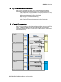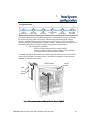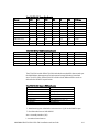
1
ATCA-S201 Installation and Use 6806800H62B July 2009 2009 Emerson All rights reserved. Trademarks Emerson, Business-Critical Continuity, Emerson Network Power and the Emerson Network Power logo are trademarks and service marks of Emerson Electric Co. © 2009 Emerson Electric Co. All other product or service names are the property of their respective owners. Intel® is a trademark or registered trademark of Intel Corporation or its subsidiaries in the United States and other countries. Java™ and all other Java-based marks are trademarks or registered trademarks of Sun Microsystems, Inc. in the U.S. and other Countries. Microsoft®, Windows® and Windows Me® are registered trademarks of Microsoft Corporation; and Windows XP™ is a trademark of Microsoft Corporation. PICMG®, CompactPCI®, AdvancedTCA™ and the PICMG, CompactPCI and AdvancedTCA logos are registered trademarks of the PCI Industrial Computer Manufacturers Group. UNIX® is a registered trademark of The Open Group in the United States and other countries. Notice While reasonable efforts have been made to assure the accuracy of this document, Emerson assumes no liability resulting from any omissions in this document, or from the use of the information obtained therein. Emerson reserves the right to revise this document and to make changes from time to time in the content hereof without obligation of Emerson to notify any person of such revision or changes. Electronic versions of this material may be read online, downloaded for personal use, or referenced in another document as a URL to a Emerson website. The text itself may not be published commercially in print or electronic form, edited, translated, or otherwise altered without the permission of Emerson, It is possible that this publication may contain reference to or information about Emerson products (machines and programs), programming, or services that are not available in your country. Such references or information must not be construed to mean that Emerson intends to announce such Emerson products, programming, or services in your country. Limited and Restricted Rights Legend If the documentation contained herein is supplied, directly or indirectly, to the U.S. Government, the following notice shall apply unless otherwise agreed to in writing by Emerson. Use, duplication, or disclosure by the Government is subject to restrictions as set forth in subparagraph (b)(3) of the Rights in Technical Data clause at DFARS 252.227-7013 (Nov. 1995) and of the Rights in Noncommercial Computer Software and Documentation clause at DFARS 252.227-7014 (Jun. 1995). Contact Address Emerson Network Power - Embedded Computing 2900 South Diablo Way, Suite 190 Tempe, AZ 85282 USA Contents PREFACE ................................................................................................................................................I SAFETY SUMMARY ........................................................................................................................................... I FLAMMABILITY ............................................................................................................................................... II EMI CAUTION................................................................................................................................................ II SAFETY STATEMENT ........................................................................................................................................ II CE NOTICE (EUROPEAN COMMUNITY).............................................................................................................. II NOTICE ......................................................................................................................................................... II ABOUT THIS MANUAL......................................................................................................................... IV HOW THIS MANUAL IS ORGANIZED................................................................................................................... IV CONVENTIONS USED IN THIS MANUAL............................................................................................................. IV HARDWARE PREPARATION AND INSTALLATION ................................................................................ VI UNPACKING INSTRUCTIONS ............................................................................................................................ VI ANTISTATIC PRECAUTIONS ............................................................................................................................. VI 1 ATCA-S201 OVERVIEW ................................................................................................................7 1.1 FEATURES OF THE ATCA STORAGE MODULE ...................................................................................... 7 1.2 I/O PICMG STANDARDS COMPLIANCE .............................................................................................. 8 1.3 CHASSIS I/O CONNECTIONS ............................................................................................................. 8 1.3.1 AMC card connections ............................................................................................................ 9 1.3.2 DDR2 SODIMM........................................................................................................................ 9 1.3.3 Zone 1, power backplane connections ................................................................................... 9 1.3.4 Zone 2, backplane connections .............................................................................................. 9 1.3.5 Zone 3, Advanced RTM connector .......................................................................................... 9 1.4 LEDS ........................................................................................................................................... 11 1.5 SOFTWARE DRIVER SUPPORT........................................................................................................... 12 1.6 PART NUMBER, SERIAL NUMBER, AND ADDRESS LABELS .................................................................... 12 2 ATCA-S201 INSTALLATION ........................................................................................................ 14 2.1 INSTALLATION AND REMOVAL OF THE ATCA CARRIER BLADE ............................................................... 14 2.2 IMPORTANT INFORMATION ABOUT YOUR CHASSIS ............................................................................. 14 2.3 SAFETY STATEMENT....................................................................................................................... 14 2.3.1 Observe maximum module current requirements................................................................ 14 2.4 BEFORE YOU INSTALL OR REMOVE THE ATCA CARRIER BLADE ............................................................. 15 2.4.1 Observe ESD Precautions ...................................................................................................... 15 2.4.2 Watch for Bent Pins or Other Damage.................................................................................. 15 2.5 USE CAUTION WHEN INSTALLING OR REMOVING THE ATCA CARRIER .................................................. 15 2.5.1 Preserve EMI Compliance ...................................................................................................... 15 2.5.2 Understand Hot Swap........................................................................................................... 16 2.6 CONNECTOR MECHANICAL KEYING ................................................................................................. 16 2.7 VERIFY SLOT USAGE ...................................................................................................................... 16 2.8 INSTALLING THE ATCA CARRIER BLADE ............................................................................................ 16 2.9 REMOVING THE ATCA CARRIER BLADE ............................................................................................. 18 2.10 VERIFYING THE HARDWARE INSTALLATION ....................................................................................... 18 2.10.1 To Verify the Hardware Installation ...................................................................................... 19 3 NEW SYSTEM CONFIGURATION................................................................................................. 20 3.1 RS232 CONSOLE PORT ................................................................................................................. 21 3.1.1 System boot overview ........................................................................................................... 21 3.1.2 Flash boot device contents.................................................................................................... 22 3.1.3 Linux serial console shell window ......................................................................................... 23 3.2 DEFAULT BLADE LOGIN ACCOUNTS AND PASSWORDS ......................................................................... 23 3.2.1 Password change procedure................................................................................................. 23 3.2.2 Password recovery procedure ............................................................................................... 23 3.3 FACTORY RESET ............................................................................................................................ 24 3.4 CONFIGURING A NEW ATCA-S201 BLADE ....................................................................................... 24 3.4.1 Serial ports ............................................................................................................................ 24 3.4.2 Ethernet ports ....................................................................................................................... 24 3.4.3 Management Configuration via HTML browser.................................................................... 25 3.4.4 Management configuration via secure shell (SSH) ............................................................... 25 3.4.5 Management configuration via serial console shell.............................................................. 25 3.5 COMMAND LINE CONFIGURATION TOOL ........................................................................................... 26 3.5.1 Change IP address of any Ethernet resource ......................................................................... 26 3.5.2 Shell, configuration scripting options................................................................................... 28 3.6 NEW SYSTEM CONFIGURATION, NO DHCP SERVER ........................................................................... 29 3.6.1 U-boot console tool............................................................................................................... 30 3.6.2 Essential U-boot user commands ......................................................................................... 30 3.6.3 U-boot environment variables .............................................................................................. 31 3.6.4 Manually assign management IP addresses ......................................................................... 32 3.7 NETWORK BOOT PROCEDURE ......................................................................................................... 33 4 NETWORK CONFIGURATION ..................................................................................................... 34 4.1 ENABLE HTML BROWSER ACCESS.................................................................................................... 35 4.2 HTML SECURITY CERTIFICATES (HTTPS:// ) ...................................................................................... 35 4.3 HTML LOGIN SCREEN .................................................................................................................... 35 4.3.1 Auto logout inactivity period ................................................................................................ 36 4.3.2 Single session management override ................................................................................... 36 4.4 HTML HOME PAGE ....................................................................................................................... 36 4.5 ESSENTIAL SYSTEM CONFIGURATION STEPS ...................................................................................... 37 4.6 SYSTEM IDENTIFICATION AND TIME ZONE ATTRIBUTES ....................................................................... 38 4.6.1 Hostname ............................................................................................................................. 39 4.6.2 Domain Name ...................................................................................................................... 39 4.6.3 Date ...................................................................................................................................... 39 4.6.4 Time ...................................................................................................................................... 40 4.6.5 Time Zone ............................................................................................................................. 40 4.6.6 Name Server list .................................................................................................................... 41 4.6.7 NTP Server list ....................................................................................................................... 41 4.6.8 Network time protocol - NTP (On/Off) .................................................................................. 42 4.6.9 Ethernet network port identification .................................................................................... 42 4.6.10 Enable (online/offline)........................................................................................................... 43 4.6.11 DHCP..................................................................................................................................... 43 4.6.12 IP address .............................................................................................................................. 43 6806800H62B ATCA-S201ATCA-S201 Installation and Use Guide ii 4.6.13 Network (Subnet) mask ........................................................................................................ 43 4.6.14 Broadcast.............................................................................................................................. 44 4.6.15 Gateway................................................................................................................................ 44 4.6.16 MTU size................................................................................................................................ 44 4.6.17 MAC address ......................................................................................................................... 44 4.7 VLAN VIRTUAL LOCAL AREA NETWORK SUPPORT ............................................................................. 45 4.7.1 Viewing active VLAN ............................................................................................................. 46 4.8 LINK AGGREGATION AND BONDING.................................................................................................. 47 4.8.1 Bonding, CLI command syntax ............................................................................................. 48 4.9 SHELF COMMUNICATIONS .............................................................................................................. 49 4.10 I/O STATUS ATTRIBUTES ................................................................................................................ 50 4.11 BLADE MAINTENANCE, MISCELLANEOUS OPERATIONS ......................................................................... 51 4.11.1 Rescan SAS Topology, disk refresh ........................................................................................ 52 4.11.2 Software Reset SAS Controller .............................................................................................. 52 4.11.3 Reset I/O Status counters...................................................................................................... 52 4.12 CPU STATUS ATTRIBUTES .............................................................................................................. 53 4.13 ATCA STATUS ATTRIBUTES ............................................................................................................ 54 5 RAID VOLUME CONFIGURATION ............................................................................................... 57 5.1 HARDWARE RAID CONFIGURATION ................................................................................................ 57 5.1.1 JBOD mode............................................................................................................................ 58 5.2 HARDWARE RAID CONFIGURATION MENU USAGE ............................................................................ 58 5.2.1 Hardware RAID levels and capabilities .................................................................................. 60 5.2.2 How new RAID definitions alter device menu display ........................................................... 60 5.2.3 Modify existing RAID configurations..................................................................................... 61 5.3 SOFTWARE RAID CONFIGURATION ................................................................................................. 63 5.3.1 Software RAID web-configuration menu usage.................................................................... 63 5.3.2 Software RAID, CLI command syntax ................................................................................... 64 5.3.3 Software RAID levels and capabilities ................................................................................... 66 6 PREPARE LOGICAL VOLUMES FOR ISCSI OR FILE SHARING......................................................... 67 6.1 BENEFITS OF A LOGICAL VOLUME GROUP (/DEV/VGA)........................................................................ 67 6.1.1 Benefits of a Logical device/disk (/dev/vga/lva0) .................................................................. 67 6.2 VIEWING PHYSICAL DISKS ............................................................................................................... 68 6.2.1 Interpreting physical disk status ........................................................................................... 68 6.2.2 View physical disk properties ................................................................................................ 69 6.3 CREATE A LOGICAL VOLUME GROUP (/DEV/VGA) .............................................................................. 70 6.4 CREATING A LOGICAL DEVICE (/DEV/VGA/LVA0)............................................................................... 73 6.4.1 Extend/Expand a Logical Device (/dev/vga/lva0) .................................................................. 73 6.4.2 Delete a Logical device (/dev/vga/lva0) ................................................................................ 74 6.5 MANAGE SHARES (PREPARE LOGICAL DEVICE FOR SERVICE) ................................................................. 75 6.5.1 Commit a logical drive for iSCSI service ................................................................................ 75 6.5.2 Commit a logical drive for NAS service.................................................................................. 76 6.5.3 Un-commit an iSCSI share .................................................................................................... 77 6.5.4 Un-commit an NFS/SMB share.............................................................................................. 78 6.6 RE-NAME ISCSI SHARES, MAKE MORE ‘HUMAN-FRIENDLY’.................................................................. 79 7 ISCSI DEVICE SETUP TOOLS ....................................................................................................... 80 6806800H62B ATCA-S201ATCA-S201 Installation and Use Guide iii ISCSI CONFIGURATION MENU ......................................................................................................... 80 7.1 7.1.1 Add or create an iSCSI target ................................................................................................ 80 7.1.2 Add or create an iSCSI LUN.................................................................................................... 81 7.1.3 Remove an individual iSCSI LUN ........................................................................................... 83 7.1.4 Delete an iSCSI Target (and all LUNS) ................................................................................... 83 7.1.5 Advanced iSCSI configuration (expert mode) ....................................................................... 84 7.1.6 iSCSI Discovery filter configuration (expert mode)................................................................ 88 8 NFS/SMB SHARE SETUP TOOLS .................................................................................................. 89 8.1 NFS AND SMB MOUNT POINT CONFIGURATION MENUS ..................................................................... 89 8.1.1 Export an nfs or smb share.................................................................................................... 90 8.1.2 Remove an individual file-share Export................................................................................. 92 8.1.3 Advanced file share configuration (expert mode)................................................................. 93 9 BLADE MAINTENANCE AND FIRMWARE UPGRADES .................................................................. 95 9.1 BLADE MAINTENANCE ................................................................................................................... 95 9.1.1 Backup your blade configuration.......................................................................................... 95 9.1.2 Import (restore) a blade configuration ................................................................................. 96 9.2 ATCA FIRMWARE ......................................................................................................................... 96 9.2.1 Download New Firmware package....................................................................................... 97 9.3 NORMAL FIRMWARE UPDATE PROCEDURES ...................................................................................... 97 9.3.1 Web flash tool, update procedure details ............................................................................. 97 9.3.2 flash_update.sh tool usage and options .............................................................................. 99 9.3.3 CLI flash tool, update procedure details.............................................................................. 100 9.4 EMERGENCY FIRMWARE RECOVERY, THEORY OF OPERATION ............................................................. 101 9.4.1 Jumper Settings................................................................................................................... 101 9.4.2 Emergency flash recovery (factory reset) ............................................................................ 102 9.4.3 Clear root password............................................................................................................ 103 10 ATCA-S201 MECHANICAL AND CONNECTOR INFORMATION.................................................. 105 10.1 SPECIFICATIONS FOR THE ATCA-S201.......................................................................................... 105 10.1.1 Physical dimensions............................................................................................................ 105 10.1.2 Power Requirements ........................................................................................................... 105 10.1.3 Environmental Specifications and Compliance................................................................... 105 10.1.4 NEBS Compliance................................................................................................................ 106 10.1.5 Electromagnetic Compliance.............................................................................................. 106 10.2 CONNECTORS AND PIN ASSIGNMENTS ........................................................................................... 107 10.2.1 AMC Module Slots ............................................................................................................... 108 10.2.2 Zone 1 Connectors.............................................................................................................. 110 10.2.3 Zone 2 Connectors.............................................................................................................. 111 10.2.4 Zone 3 Connectors.............................................................................................................. 112 10.2.5 Power Supply Mezzanine Module ....................................................................................... 117 10.2.6 SODIMM DDR Module......................................................................................................... 117 11 RTM-ATCA-SXXX OVERVIEW ................................................................................................... 118 11.1 11.2 11.3 FEATURES OF THE ADVANCED REAR TRANSITION MODULE ............................................................... 118 I/O PICMG STANDARDS COMPLIANCE.......................................................................................... 118 I/O INTERFACES .......................................................................................................................... 118 6806800H62B ATCA-S201ATCA-S201 Installation and Use Guide iv 11.3.1 External SAS Connector....................................................................................................... 119 11.3.2 Ethernet Management Port (RJ-45)..................................................................................... 119 11.3.3 Serial Console Port (RJ-45) .................................................................................................. 120 11.4 LEDS ......................................................................................................................................... 120 11.5 SOFTWARE SUPPORT ................................................................................................................... 121 11.6 PRODUCTS SUPPORTED BY THIS MANUAL....................................................................................... 121 11.7 IDENTIFICATION LABELS ............................................................................................................... 121 12 RTM-ATCA-SXXX INSTALLATION ............................................................................................. 124 12.1 INSTALLATION AND REMOVAL OF THE REAR TRANSITION MODULE .................................................... 124 12.2 IMPORTANT INFORMATION ABOUT YOUR CHASSIS .......................................................................... 124 12.2.1 Safety Statement ................................................................................................................ 124 12.2.2 Observe Maximum Module Current Requirements............................................................. 124 12.3 BEFORE YOU INSTALL OR REMOVE THE RTM ................................................................................. 125 12.3.1 Observe ESD Precautions .................................................................................................... 125 12.3.2 Watch for Bent Pins or Other Damage................................................................................ 125 12.4 USE CAUTION WHEN INSTALLING OR REMOVING RTM.................................................................... 126 12.4.1 Preserve EMI Compliance .................................................................................................... 126 12.4.2 Understand Hot Swap......................................................................................................... 126 12.5 VERIFY SLOT USAGE .................................................................................................................... 126 12.6 INSTALLING THE ADVANCED REAR TRANSITION MODULE ................................................................. 126 12.7 REMOVING THE ADVANCED REAR TRANSITION MODULE .................................................................. 128 12.8 VERIFYING THE HARDWARE INSTALLATION ..................................................................................... 128 13 RTM-ATCA-SXXX MECHANICAL AND CONNECTOR INFORMATION ......................................... 129 13.1 SPECIFICATIONS FOR THE RTM-ATCA-SXXX ................................................................................ 129 13.1.1 Physical Dimensions ........................................................................................................... 129 13.1.2 Power Requirements ........................................................................................................... 129 13.1.3 Environmental Specifications and Compliance................................................................... 129 13.1.4 NEBS Compliance................................................................................................................ 130 13.1.5 Electromagnetic Compliance.............................................................................................. 130 13.2 CONNECTORS AND PIN ASSIGNMENTS ........................................................................................... 131 13.2.1 SAS Connector Port ............................................................................................................. 132 13.2.2 10/100/1000 Mb Management Port .................................................................................. 133 13.2.3 Serial Console Management Port........................................................................................ 134 13.2.4 Zone 3 Connectors.............................................................................................................. 134 14 IPMI FUNCTIONS LIST .............................................................................................................. 139 14.1 IPMI AND MANAGEMENT CONTROLLER (IPMC)............................................................................. 139 14.2 SENSOR DATA RECORDS ............................................................................................................... 139 14.2.1 RTM e-Keying Port Assignments ........................................................................................ 14‐2 14.3 SUPPORTED IPMI COMMANDS .................................................................................................... 14‐3 15 IPMC FIRMWARE UPGRADE PROCEDURE................................................................................ 15‐1 15.1 16 THE IPMITOOL UTILITY................................................................................................................. 15‐1 INDEX ..................................................................................................................................... 16‐3 6806800H62B ATCA-S201ATCA-S201 Installation and Use Guide v List of Figures Figure 1, ATCA-S201 functional block diagram.......................................................................................... 9 Figure 3 ATCA-S201 Diagram Showing Identification Label Location .................................................... 13 Figure 4 Injector / Ejector latch and locking screw ................................................................................... 17 Figure 5 Management communications port location diagram (Typical).............................................. 20 Figure 6 ATCA Blade boot sequence diagram........................................................................................... 22 Figure 7 Boot-Flash device contents.......................................................................................................... 22 Figure 8 HTML tool, startup screen............................................................................................................ 37 Figure 9 Emerson ATCA-S201 Maintenance Network .................................................................... 38 Figure 10 Link aggregation 802.3ad (bonding), theory of operation ..................................................... 47 Figure 11 HTML tool, Emerson ATCA-S201 MaintenanceShelf ...................................................... 49 Figure 12 HTML tool, Emerson ATCA-S201 MaintenanceIO Status................................................ 50 Figure 13 HTML tool, Emerson ATCA-S201 MaintenanceCPU Status ............................................ 53 Figure 14 HTML tool, Emerson ATCA-S201 MaintenanceATCA Status .......................................... 54 Figure 15 HTML tool, Main navigation side-bar, Hardware RAID->Configuration ................................. 58 Figure 16 Emerson ATCA-S201 Hardware RAID (new installation screen-shot) ............................... 59 Figure 17 Figure shows how RAID LUN definitions alter physical disk display ....................................... 61 Figure 19 Emerson ATCA-S201 MD RAID (new installation screen-shot) .......................................... 63 Figure 20 HTML tool, Emerson ATCA-S201 Physical Disk (summary screen)..................................... 68 Figure 22 HTML tool, Main navigation side-bar, LVM2->Configuration ................................................. 70 Figure 23 HTML tool, Emerson ATCA-S201 LVM2 Configuration........................................................ 71 Figure 25 HTML tool, Manage shares menu function .............................................................................. 75 Figure 26 HTML tool, Emerson ATCA-S201 iSCSI iSCSI Configuration............................................ 81 Figure 27 SCSI configuration screen updates to show the new LUN. ..................................................... 83 Figure 28 HTML tool, Emerson ATCA-S201 nfs nfs Configuration.................................................. 90 Figure 29 HTML tool, Emerson ATCA-S201 smb smb Configuration ............................................. 91 Figure 30 ATCA-S201 Jumper locations .................................................................................................. 102 Figure 31 ATCA-S201 ATCA Module Connectors .................................................................................. 108 Figure 32 Zone 1 J10 Connector Port Pin Location Diagram................................................................. 111 Figure 33 Zone 2 Connector Port Pin Location Diagram........................................................................ 112 Figure 34 Zone 3, Connector Port Pin Location Diagram...................................................................... 113 Figure 35 ‘J30’ RTM Power Receptacle .................................................................................................... 116 Figure 36, RTM-ATCA-SXXX Functional Interconnect Diagram ............................................................ 119 Figure 37, Ethernet Management Port.................................................................................................... 120 Figure 38 RTM-ATCA-SXXX Front Panel LEDs......................................................................................... 121 Figure 39. RTM-ATCA-SXXX Top View (Two Disk Drives)...................................................................... 121 Figure 40 RTM-ATCA-SXXX Diagram Showing Identification Label Locations..................................... 123 Figure 41 Injector / Ejector Latch and Locking Screw............................................................................. 127 Figure 42 RTM-ATCA-SXXX Connectors.................................................................................................. 132 Figure 43. RTM-ATCA-SXXX Front Panel SAS Connector Pin-Out Diagram ......................................... 132 Figure 44 10/100/1000 Mb Management Port Pin Location Diagram ................................................. 133 Figure 45 Serial Console Management Port Pin Location Diagram....................................................... 134 Figure 46 Zone 3, Connector Port Pin Location Diagram ...................................................................... 135 Figure 47 ‘J30’ RTM Power Receptacle .................................................................................................... 137 6806800H62B ATCA-S201ATCA-S201 Installation and Use Guide vi List of Tables Table 1 Conventions used in this manual.................................................................................................... iv Table 2 LED functional description ............................................................................................................ 12 Table 3 ATCA-S201 Identification Labels.................................................................................................. 12 Table 4 Max ATCA-S201 module Current requirements......................................................................... 14 Table 5 Console port, default terminal settings ....................................................................................... 21 Table 6 Built-in user accounts included on a new ATCA-S201................................................................. 23 Table 7 Ethernet ports for chassis communications (base/fabric).......................................................... 26 Table 8 Essential U-boot configuration commands ................................................................................. 30 Table 9 U-boot environment variables shown with printenv .................................................................. 31 Table 10 CLI command syntax, enable/disable GUI access ..................................................................... 35 Table 11 CLI command syntax, single session management override ................................................... 36 Table 12 CLI command syntax, set network property: hostname .......................................................... 39 Table 13 CLI command syntax, set network property: domain name .................................................... 39 Table 14 CLI command syntax, set network property: system date ....................................................... 40 Table 15 CLI command syntax, set network property: system time....................................................... 40 Table 16 CLI command syntax, set network property: system time zone.............................................. 40 Table 17 Time Zone Selections .................................................................................................................. 41 Table 18 CLI command syntax, set network property: assign Name server........................................... 41 Table 19 CLI command syntax, set network property: assign NTP server .............................................. 42 Table 20 Ethernet ports for chassis communications (base/fabric)........................................................ 42 Table 21 CLI command syntax, set network property: Ethernet port configuration ............................. 43 Table 22 Shelf configuration menu parameters....................................................................................... 50 Table 23 Blade, I/O Status indication......................................................................................................... 51 Table 24 ATCA status indication ................................................................................................................ 55 Table 25 CLI command syntax, blade_status for ATCA and AMC site status ......................................... 56 Table 26 CLI command syntax, set_raid: Add RAID configuration.......................................................... 59 Table 27 CLI command syntax, mdadm: manage RAID configuration ................................................... 64 Table 28 CLI command syntax, create new volume groups .................................................................... 72 Table 29 CLI command syntax, create new logical device....................................................................... 73 Table 30 CLI command syntax, create iSCSI share ................................................................................... 76 Table 31 CLI command syntax, format a logical volume ......................................................................... 77 Table 32 CLI command syntax, create iSCSI share ................................................................................... 81 Table 33 iSCSI Advanced configuration and parameter definitions........................................................ 86 Table 34 CLI command syntax, create nfs share....................................................................................... 91 Table 35 CLI command syntax, create smb share .................................................................................... 92 Table 36 Common nfs export option definitions...................................................................................... 94 Table 37 JP1, jumper for primary/recovery Flash selection ................................................................... 101 Table 38 JP2, jumper for clearing master password ............................................................................... 101 Table 39 Environmental specifications for the ATCA-S201 ................................................................... 106 Table 40 EMC Emission compliancy ........................................................................................................ 107 Table 41 Connector Port Identification and Location ............................................................................ 108 Table 42 AMC Slot 0, Port Assignments .................................................................................................. 109 Table 43 AMC Slot 1, Port Assignments .................................................................................................. 109 Table 44 AMC slot 2, Port Assignments .................................................................................................. 110 Table 45 AMC slot 3, Port Assignments .................................................................................................. 110 Table 46 Connector J10, Zone-1 Pin Assignments ................................................................................. 111 Table 47 Connector J23, Zone-2 Pin Assignments ................................................................................. 112 Table 48 Connector J23, Zone-2 Signal Descriptions............................................................................. 112 Table 49 Connector P32, Management infrastructure pin assignments.............................................. 113 Table 50 Connector J32, Management infrastructure signal descriptions........................................... 114 6806800H62B ATCA-S201ATCA-S201 Installation and Use Guide vii Table 51 Connector J33, PCIe and Miscellaneous RTM Pin Assignments ............................................. 114 Table 52 Connector J33, PCIe and Miscellaneous RTM Signal Descriptions ......................................... 115 Table 53 J30, RTM Power Pin Header Assignment.................................................................................. 116 Table 54 Connector J30, RTM Power Pin Signal Descriptions................................................................ 116 Table 55 I/O Ports Available on RTM Faceplate ...................................................................................... 119 Table 56 LEDs On RTM Faceplate............................................................................................................. 120 Table 57 RTM-ATCA-SXXX Identification Labels..................................................................................... 122 Table 58 Max RTM Module Current Requirements ................................................................................ 124 Table 59 Max RTM Module Current Requirements ................................................................................ 129 Table 60 Environmental Specifications for the ATCA-S201................................................................... 130 Table 61 EMC Emission Compliancy........................................................................................................ 131 Table 62 Connector Port Identification and Location ............................................................................ 132 Table 63. RTM-ATCA-SXXX Front Panel SAS Connector Pin Assignments .......................................... 133 Table 64 10/100/1000 Management Port Connector Pin Assignments .............................................. 133 Table 65 Serial Console Management Port Connector Pin Assignments ............................................. 134 Table 66 Connector P32, Management Infrastructure Pin Assignments ............................................. 135 Table 67 Connector J32, Management Infrastructure Signal Descriptions .......................................... 136 Table 68 Connector J33, Miscellaneous RTM Pin Assignments ............................................................. 136 Table 69 Connector J33, Miscellaneous RTM Signal Descriptions......................................................... 137 Table 70 J30, RTM Power Pin Header Assignment.................................................................................. 137 Table 71 Connector J30, RTM Power Pin Signal Descriptions................................................................ 138 Table 72. ATCA-S201 Sensor Data Records ........................................................................................... 14‐1 Table 73. RTM-ATCA-SXXX Sensor Data Records.................................................................................. 14‐1 Table 74 ATCA-S201 Example FRU Data Records.................................................................................. 14‐1 Table 75 RTM-ATCA-SXXX Example FRU Data Records ........................................................................ 14‐2 Table 76 Supported IPMI Commands..................................................................................................... 14‐4 Table 77 ipmitool options relevant to firmware upgrades ................................................................... 15‐1 6806800H62B ATCA-S201ATCA-S201 Installation and Use Guide viii Preface Safety Summary The following general safety precautions must be observed during all phases of operation, service, and repair of this equipment. Failure to comply with these precautions or with specific warnings elsewhere in this manual could result in personal injury or damage to the equipment. The safety precautions listed below represent warnings of certain dangers of which Emerson is aware. You, as the user of the product, should follow these warnings and all other safety precautions necessary for the safe operation of the equipment in your operating environment. GROUND THE INSTRUMENT. To minimize shock hazard, the equipment chassis and enclosure must be connected to an electrical ground. If the equipment is supplied with a three-conductor AC power cable, the power cable must be plugged into an approved three-contact electrical outlet, with the grounding wire (green/yellow) reliably connected to an electrical ground (safety ground) at the power outlet. The power jack and mating plug of the power cable meet International Electrotechnical Commission (IEC) safety standards and local electrical regulatory codes. DO NOT OPERATE IN AN EXPLOSIVE ATMOSPHERE. Do not operate the equipment in any explosive atmosphere such as in the presence of flammable gases or fumes. Operation of any electrical equipment in such an environment could result in an explosion and cause injury or damage. KEEP AWAY FROM LIVE CIRCUITS INSIDE THE EQUIPMENT. Operating personnel must not remove equipment covers. Only Factory Authorized Service Personnel or other qualified service personnel may remove equipment covers for internal subassembly or component replacement or any internal adjustment. Service personnel should not replace components with power cable connected. Under certain conditions, dangerous voltages may exist even with the power cable removed. To avoid injuries, such personnel should always disconnect power and discharge circuits before touching components. USE CAUTION WHEN EXPOSING OR HANDLING A CRT. Breakage of a Cathode-Ray Tube (CRT) causes a high-velocity scattering of glass fragments (implosion). To prevent CRT implosion, do not handle the CRT, and avoid rough handling or jarring of the equipment. Handling of a CRT should be done only by qualified service personnel using approved safety mask and gloves. DO NOT SUBSTITUTE PARTS OR MODIFY EQUIPMENT. Do not install substitute parts or perform any unauthorized modification of the equipment. Contact your local Emerson representative for service and repair to ensure that all safety features are maintained. OBSERVE WARNINGS IN MANUAL. Warnings, such as the example below, precede potentially dangerous procedures throughout this manual. Instructions contained in the warnings must be followed. You should also employ all other safety precautions which you deem necessary for the operation of the equipment in your operating environment. Warning To prevent serious injury or death from dangerous voltages, use extreme caution when handling, testing, and adjusting this equipment and its components. 6806800H62B ATCA-S201ATCA-S201 Installation and Use Guide i Preface Flammability All Emerson PWBs (printed wiring boards) are manufactured with a flammability rating of 94V-0 by UL-recognized manufacturers. EMI Caution This equipment generates, uses, and can radiate electromagnetic energy. It may cause or be susceptible to electromagnetic interference (EMI) if not installed and used with adequate EMI protection. Safety Statement The ATCA-S201 is designed to comply with EN60950-1, and is intended to be used with similarly tested ATCA and AMC products that have a user’s guide detailing user installation of AMC module accessories. CE Notice (European Community) Emerson Networks products with the CE marking comply with the EMC Directive (89/336/EEC). Compliance with this directive implies conformity to the following European Norms: EN55022 “Limits and Methods of Measurement of Radio Interference Characteristics of Information Technology Equipment”; this product tested to Equipment Class A EN50082-1:1997 “Electromagnetic Compatibility–Generic Immunity Standard, Part 1. Residential, Commercial and Light Industry” System products also fulfill EN60950 (product safety), which is essentially the requirement for the Low Voltage Directive (73/23/EEC). Board products are tested in a representative system to show compliance with the above mentioned requirements. A proper installation in a CE-marked system will maintain the required EMC/safety performance. In accordance with European Community directives, a “Declaration of Conformity” has been made and is on file within the European Union. The “Declaration of Conformity” is available on request. Please contact your sales representative. Notice While reasonable efforts have been made to assure the accuracy of this document, Emerson Networks, Inc. assumes no liability resulting from any omissions in this document, or from the use of the information obtained therein. Emerson reserves the right to revise this document and to make changes from time to time in the content hereof without obligation of Emerson to notify any person of such revision or changes. Electronic versions of this material may be read online, downloaded for personal use. The text itself may not be published commercially in print or electronic form, 6806800H62B ATCA-S201ATCA-S201 Installation and Use Guide ii Preface edited, translated, or otherwise altered without the permission of Emerson Networks, Inc. 6806800H62B ATCA-S201ATCA-S201 Installation and Use Guide iii About This Manual This manual supports the following configurations and model numbers. Part Number Description ATCA-S201 10GbE RAID Storage-IP Carrier blade How this manual is organized This manual is divided into the following chapters and appendices: Chapter 1 provides a ATCA-S201 Overview 6 Chapter 2 provides instructions for Installation Chapter 3 provides the procedures for a New System configuration 6 Chapter 4 Provides details regarding Network configuration Chapter 5 provides details for RAID Volume Configuration Chapter 6 provides instructions for sharing devices as NAS or iSCSI Chapter 7 provides information for iSCSI LUN configurations Chapter 8 provides information for NFS and SMB file sharing configurations Chapter 9 provides Blade Maintenance and Firmware upgrades 6 Chapter 10 provides ATCA-S201 Mechanical and Connector Information 6 Chapter 11 provides overview on RTM-ATCA-SXXX Chapter 12 provides instructions for installing the RTM-ATCA-SXXX Chapter 13 provides RTM-ATCA-SXXX connector information Chapter 14 provides IPMI Functions List 6 Chapter 15 provides IPMC Firmware Upgrade Procedure 6 Conventions Used in This Manual The following typographical conventions are used in this document: Table 1 Conventions used in this manual Convention Is used for bold User input that you type just as it appears; it is also used for commands, options and arguments to commands, and names of programs, directories and files. Names of variables to which you assign values, for function parameters, and for structure names and fields. Italic is also used for comments in screen displays and examples, and to introduce new terms. italic 6806800H62B ATCA-S201ATCA-S201 Installation and Use Guide iv courier ENTER CTRL System output (for example, screen displays and reports), examples, and system prompts. The carriage return or Enter key. The Control key. Execute control characters by pressing the CTRL key and the letter simultaneously, for example, Ctrl+D. 6806800H62B ATCA‐S201 Installation and Use Guide v Hardware Preparation and Installation Unpacking Instructions If the shipping carton is damaged upon receipt, request that the carrier’s agent be present during the unpacking and inspection of the equipment. Unpack the equipment from the shipping carton. Refer to the packing list and verify that all items are present. Save the packing material for storing and reshipping of equipment. Avoid touching areas of integrated circuitry. Static discharge can damage circuits. After removing the product from the packaging: Check for obvious physical damage. Make sure that you disconnect the chassis from the main power supply before you continue. Antistatic Precautions Emerson strongly recommends that you use an antistatic wrist strap and a conductive foam pad when installing or upgrading a system. Electronic components, such as disk drives, computer boards, and memory modules, can be extremely sensitive to electrostatic discharge (ESD). After removing the component from its protective wrapper or from the system, place the component flat on a grounded, static-free surface (and, in the case of a board, component side up). Do not slide the component over any surface. If an ESD station is not available, you can avoid damage resulting from ESD by wearing an antistatic wrist strap (available at electronics stores) that is attached to an active electrical ground. Note that a system chassis may not be grounded if it is unplugged. Dangerous voltages, capable of causing death, are present in this equipment. Use extreme caution when handling, testing, and adjusting. Avoid touching areas of integrated circuitry. Static discharge can damage these circuits. 6806800H62B ATCA-S201ATCA-S201 Installation and Use Guide vi ATCA-S201 Overview 1 ATCA-S201 Overview The Emerson ATCA-S201 is an ATCA carrier blade that supplies multi-protocol IP storage services to the chassis Zone-2 backplane using Ethernet connections. The ATCA-S201 virtualizes capacity of AMC SAS/SATA disks and creates multiple logical volumes which are mapped as iSCSI, NFS or SMB targets. Using access control lists, ATCA server blades are given authorization to connect with virtualized volumes via 10 GbE fabric or 1GbE base connections. The ATCA-S201 carrier can accommodate up to four AMC disk modules. Additional disks may be added using an Advanced ARTM which adheres to the Advanced RTM zone-3 connector pin out. Users may also deploy the ATCA-S201 to realize gateway functions with external equipment including SAS and/or Fiber channel (FC) storage area networks (SANs). For example, populate with an AMC 4 Gb FC controller modules, and establish gateway services between LUN volumes in the FC data center and the ATCA GbE network. 1.1 Features of the ATCA Storage Module The ATCA-S201 is single slot carrier board for ATCA shelves. Measuring 8U (280mm) x 325 mm, the carrier includes four advanced mezzanine card (AMC) slots for storage disks or SAN connections. Several on board Ethernet controllers provide connections to the base and fabric interfaces. The prominent digital components include: Freescale® 1.3Ghz, super scalar PowerPC processor Intel® dual port 10 GbE Ethernet controller LSI® 8 port SAS controller, with RAID PLX® 48 Lane PCI Express Switch 1GB SODIMM, 533MHz DDR2, with ECC (72b) Carrier IPMC, with hot swap and LED control FRUID serial EERPORM (note: The FRU ID is not a separate part but rather embedded in the MMC controller.) Temperature sensors Voltage sensors SPI flash memory The ATCA-S201 is loaded with software which enables it to terminate several IP protocols, and efficiently map these protocols to block I/O storage using SAS/SATA disks, and optional RAID protection. This product can also map IP protocols to Fibre Channel SAN resources, if populated with a 4Gb Fibre channel AMC module. Key software services include: iSCSI service (IETF RFC-3720) NFS service version 3 (network file share) SMB service (Server Message Block file system) Integrated RAID0, RAID1 and RAID1E service SNMP HTML web configuration client 6806800H62B ATCA-S201ATCA-S201 Installation and Use Guide 7 ATCA‐S201 Overview 1.2 I/O PICMG standards compliance The ATCA-S201 10Gb RAID Storage-IP Carrier ATCA is fully compliant with the following PCI Industrial Computer Manufacturers Group (PICMG) specifications: PICMG 3.0 Advanced Telecommunications Computing Architecture (ATCA) PICMG 3.1 Ethernet for ATCA Systems AMC.0 Advance Mezzanine Card Base Specification AMC.1 PCI Express and Advanced Switching AMC.3 AMC Storage IPMI v1.5 Intelligent Platform Management Interface Specification PCI Express 1.0a 1.3 Chassis I/O connections The ATCA-S201 provides several sockets and slots to facilitate operation in an ATCA chassis. In addition to 4 AMC modules, the module includes chassis backplane connections including ATCA zone-1 (power), zone-2 (fabric) and zone-3 (Advanced rear transition module). Site B1 8 PCI-E x4 PCI-E Zone 3 to RTM 4 SATA/SAS x1 SAS 4 SATA/SAS 1 Gb x1 SAS Site B2 x4 PCI-E 8 PCI-E MPC8548E CPU 1 Gb Zone 2 DDR2, FLASH 1 Gb ATCA XAUI 10 Gb 10GigE 10 Gb x1 SAS X1 SAS 88 PCI-E PCI-E 8 SAS LSI 1068E 8 PCIE SAS/RAID Site B3 x4 PCI-E x1 SAS 24 PCI-E 24 PCI-E PLX8548 PCI-E Switch X1 SAS Site B4 x4 PCI-E IPMI (PPS) I2C x1 SAS X1 SAS 6806800H62B ATCA‐S201 Installation and Use Guide Zone 1 Power Power Module 8 ATCA‐S201 Overview Figure 1, ATCA-S201 functional block diagram 1.3.1 AMC card connections The four AMC slots have identical features, and each accommodates a half width, mid height module. The ATCA-S201 accepts AMC cards conforming to either PCI express signaling (AMC.1) or Storage signaling options (AMC.3). AMC feature support details: PCI-Express x4 on AMC ports 4-7 PCI reference clock on FCLKA 3Gb SAS/SATA on AMC port2 3Gb SAS/SATA on AMC port3 SAS hot swap support Face plate height x width, 18.96 x 73.8mm IPMB-L 72W max each slot (120W shared with all AMC slots) 1.3.2 DDR2 SODIMM A 72 bit SODIMM socket is populated with a DDR2 memory module, and operated at 533MHz. The ATCA applies ECC (error correction code) algorithms to this memory to ensure data integrity of both the storage and program code stored in it. Single bit errors are automatically detected and corrected by these ECC algorithms. 1.3.3 Zone 1, power backplane connections The Zone-1 connector brings 48V DC power into the ATCA main board. This power is regulated and split into several lower voltages by discrete components and a pair of power modules that are affixed to the ATCA carrier. Together, these devices convert 48V source and distributes power amongst the ATCA local onboard needs, AMC slots and advanced rear transition module (RTM). 1.3.4 Zone 2, backplane connections This connector carries the Ethernet links to the chassis backplane. All Ethernet ports on this connector are full duplex and all ports support access to advertised storage resources. This connector includes the following Gigabit Ethernet ports: 1.3.5 2 Fabric channels, redundant 10GbE XAUI connections 2 Base channels, redundant 1GbE base connections Zone 3, Advanced RTM connector This connector conforms to the advanced rear transition module (RTM) 3-row connector standard. The following functions are routed to this connector: 8x PCI-express 4x SAS/SATA target connections 4x SAS/SATA initiator connections I2C support 6806800H62B ATCA‐S201 Installation and Use Guide 9 ATCA‐S201 Overview 1.3.5.1 12V and 3.3V supply voltage 1GbE management RS232 management Ethernet Management port An Ethernet management port is routed to the Zone 3 connector. An advanced RTM with an RJ-45 connector is needed to access this port. The port auto negotiates to either 10/100/1000BASE-T. 1.3.5.2 Serial Console Port An RS232 serial management port is routed to the Zone 3 connector. An advanced RTM with an RJ-45 connector is needed to access this port. 6806800H62B ATCA‐S201 Installation and Use Guide 10 ATCA‐S201 Overview 1.4 LEDs Several LEDs are located on the panel of the ATCA-S201 Advanced TCA Carrier. Out of Service (OOS) OK Boot Status Hot Swap Figure 2 Front view- fully populated ATCA-S201 showing panel LEDs 6806800H62B ATCA‐S201 Installation and Use Guide 11 ATCA‐S201 Overview Table 2 LED functional description LED Description Off: Normal, default state Blue-Blinking: Preparing for hot swap Blue-ON: ready for hot-swap removal Green-ON: Blade Optimal Amber: Blade is resetting Green: Blade is optimal Off: Normal, default state Yellow-Blinking: firmware update in progress Red-ON: Out of service (PPC/IPMC) ATCA Hot Swap LED ATCA Blade OK LED ATCA Boot (Health) status ATCA Out of service (OOS) 1.5 Software driver support The ATCA-S201 provides several IP storage services over the 10GbE fabric and 1 GbE base connections. Major services include iSCSI, NFS, and SMB. ATCA node boards with standard OS installations, require no special drives from Emerson. This product is compatible with the following operating systems and services: Solaris 10 (SPARC) Operating System, NFS Solaris 10 (SPARC) Operating System, iSCSI initiator Solaris 10 (x86) Operating system, NFS Solaris 10 (x86) Operating system, iSCSI initiator SuSE Linux Enterprise Server 10, NFS SuSE Linux Enterprise Server 10, iSCSI initiator RedHat Enterprise Linux 5.0_u4, NFS RedHat Enterprise Linux 5.0_u4, iSCSI initiator Windows Server 2003 CIFS (a dialect of SMB) Windows Server 2003, iSCSI initiator 1.6 Part Number, Serial Number, and Address Labels At manufacturing time, several labels are affixed to the ATCA-S201 as shown below. For proper identification of the AMC module, use these barcode labels to determine the module identity. The barcode labels provide the following information: Table 3 ATCA-S201 Identification Labels Label Description Label 1: Top/Final assembly P/N For Internal Use Only Label 2: Sub assembly P/N For Internal Use Only Label 3: Serial number (S/N) AAA = Assembly Number (100) Format: AAALYMMSSSS (example: 100S8031234) L =Location of manufacturer (S) Y = Calendar year of manufacturer (2008 = 8) MM = Calendar month of manufacturer (March = 03) SSSS = Sequence number (reset each month) (1234) 6806800H62B ATCA‐S201 Installation and Use Guide 12 ATCA‐S201 Overview Label 4: Part Numbers This label contains 2 numbers: (example: Top = Internal Part Number 0106826G01A Bottom = Orderable Part Number ATCA-S120) Figure 3 ATCA-S201 Diagram Showing Identification Label Location 6806800H62B ATCA‐S201 Installation and Use Guide 13 2 ATCA-S201 Installation This chapter contains the procedures for installing and removing the ATCA-S201 10GbE RAID storage services blade. 2.1 Installation and removal of the ATCA carrier blade The ATCA-S201 10GbE RAID storage services blade can be installed into an ATCA shelf (chassis) with a midplane made for front and rear board installations. 2.2 Important information about your chassis The Chassis backplane often designates certain slots as hub slots and the others as general purpose node slots. Be certain to select a general purpose node slot for installation. If this installation includes a companion advanced rear transition module (ARTM), install the ARTM first. These back-to-back slots have cut-outs that permit the front carrier board to pass signals to the ARTM via the Zone-3 connector complex. Before installing the blade module, verify the module’s part number to ensure that the correct module is being installed into the system. For information on identifying the blade module, see Section 1.6 Part Number, Serial Number, and Address Labels. 2.3 Safety Statement The ATCA-S201 is designed to comply with UL60950-1, and is intended to be used with similarly tested ATCA and AMC products that have a user’s guide detailing user installation. 2.3.1 Observe maximum module current requirements Be sure to validate the host chassis, and the host chassis meets the maximum current requirements. The ATCA-S201 includes a stacked power supply module with maximum rated output of 210W of power. This represents a surplus of power vs. the expected power consumption. Table 4 Max ATCA-S201 module Current requirements Module Max ATCA blade Current Draw (unpopulated) Max current draw (each AMC slot) Max current draw (ARTM slot) ATCA-S201 72 watts (max each) 25 watts (max) 6806800H62B ATCA-S201ATCA-S201 Installation and Use Guide 1.04 @ 48V (50 watts) 2.08 @ 48V (100 watts) total shared power pool 3.12 Total Maximum 14 2.4 ATCA‐S201 Installation Before you install or Remove the ATCA carrier blade Boards may be damaged if improperly installed or handled. Please read and follow the guidelines in this section to protect your equipment. 2.4.1 Observe ESD Precautions Emerson strongly recommends that you use an antistatic wrist strap and a conductive foam pad when installing or upgrading a system. Electronic components, such as disk drives, computer boards, and memory modules, can be extremely sensitive to electrostatic discharge (ESD). After removing the component from its protective wrapper or from the system, place the component flat on a grounded, static-free surface (and, in the case of a board, component side up). Do not slide the component over any surface. If an ESD station is not available, you can avoid damage resulting from ESD by wearing an antistatic wrist strap (available at electronics stores) that is attached to an active electrical ground. Note that a system chassis may not be grounded if it is unplugged. 2.4.2 Watch for Bent Pins or Other Damage Bent pins or loose components can cause damage to the board, the backplane, or other system components. Carefully inspect your board and the backplane for both pin and component integrity before installation. Our suppliers take significant steps to ensure there are no bent pins on the backplane or connector damage to the boards prior to leaving our factory. Bent pins caused by improper installation or by boards with damaged connectors could void the warranty for the backplane or boards. If a system contains one or more crushed pins, power off the system and contact your local sales representative to schedule delivery of a replacement chassis assembly. 2.5 Use Caution When installing or removing the ATCA carrier When installing boards in an empty chassis, we recommend that you start at the left of the card cage and work to the right. This helps to avoid mistakes in matching slots with the intended carrier boards. When inserting or removing a board in a slot adjacent to other boards, use extra caution to avoid damage to the pins and components located on the primary or secondary sides of the boards. 2.5.1 Preserve EMI Compliance To preserve compliance with applicable standards and regulations for electromagnetic interference (EMI), during operation all front and rear openings on 6806800H62B ATCA‐S201 Installation and Use Guide 15 ATCA‐S201 Installation the chassis or board faceplates must be filled with an appropriate card or covered with a filler panel. If the EMI barrier is open, devices may cause or be susceptible to excessive interference. 2.5.2 Understand Hot Swap The ATCA module is electrically designed for hot swap within a fully powered chassis. To facilitate hot swap, there is a blue LED on the front faceplate. This LED is under software control of the IPMC managers. The manager will illuminate the blue hot swap LED on the front faceplate when software has stopped and it is safe to remove the advanced rear transition module. If the blue-LED is not illuminated or blinking, it is not ready for removal. Powering down or removing a board before the operating system or other software running on the board has been properly shut down may cause corruption of data or file systems. 2.6 Connector Mechanical keying The ATCA supports mechanical connector keying to help prevent installation with incompatible components and RTM. The ATCA carrier board utilizes an A1/K1 key that is set at for universal) 2.7 Verify Slot Usage Prevent possible damage to module components by verifying the proper slot usage for your configuration. In most cases, electronic keying (E-keying) will prevent power on of a board into an incompatible slot. However, as an extra precaution, you should be familiar with the slot purpose. 2.8 Installing the ATCA carrier blade This section describes a recommended procedure for installing the ATCA carrier module in a chassis. Before you install your module, please read all cautions, warnings, and instructions presented in this section. Handling modules and peripherals can result in static damage. Use a grounded wrist strap, static-dissipating work surface, and antistatic containers when handling and storing components. Insert the board by holding the Module Handles–do not exert unnecessary pressure on the faceplate. Hot swap compliant modules may be installed while the system is powered on. If a module is not hot swap compliant, you should remove power to the slot or system before installing the module. 1. Verify that you have taken the necessary antistatic precautions. 6806800H62B ATCA‐S201 Installation and Use Guide 16 2. ATCA‐S201 Installation Go to the front of the system and choose an appropriate slot for the ATCA carrier blade. If also installing a companion advanced rear transition module (RTM), install it before installing the ATCA node board. For example, if the ATCA node board is planned for slot B4, first install the ARTM at the back of the system in slot B4. 3. Remove the slot filler panel from the selected node board slot, if necessary. 4. Prepare the module by loosening the locking screws and opening the injector/ejector latch at the top and bottom of the module as shown in the figure below. Figure 4 Injector / Ejector latch and locking screw 5. Carefully align the edges of the module with the guides in the appropriate slot. It might be helpful to look into the enclosure to verify correct alignment of the rails in the guides. Align the edges of the module with the card cage rail guides in the appropriate slot. 6. Taking care to keep the module aligned in the guides, apply equal and steady pressure and slide the module in until the injector/ejector mechanism engages the retention bars. 7. Position your thumbs at the top and bottom of the ATCA carrier board; simultaneously push in the module and rotate the injector/ejector mechanisms inward to their closed position to seat and secure ATCA carrier blade. DO NOT FORCE THE BOARD INTO THE SLOT. 8. Tighten the two module retention screws to secure the module into the shelf. 6806800H62B ATCA‐S201 Installation and Use Guide 17 9. 2.9 ATCA‐S201 Installation Power on the system, if necessary. Refer to your system manual for instructions on correctly powering on the system. Once power is applied to the chassis, the internal MMC controller runs a self-test that runs for approximately 10 seconds. Upon a successful power up self-test, the blue hot swap LED will blink and then turn off, indicating that the module has been placed in operation. Removing the ATCA carrier blade The ATCA-S201 ATCA carrier blade is hot-swappable and can be removed from a powered chassis. This section describes a recommended procedure for removing a board module from a chassis. Before you remove your module, please read all cautions, warnings, and instructions presented in this section. Hot swap compliant modules may be removed while the system is powered on. When the lower ejector handle is partially disengaged, a mechanical switch will assert a signal to notify the IPMC to begin removal preparations. The IPMC will blink the blue hot-swap LED as it transitions the module to the appropriate power-down state. Upon completion and with permission from the ShMC, The blue LED will illuminate steady ON. This is the only indication that safe removal may commence. If the Blue LED is blinking or off, it is not ready for hot plug. To remove the ATCA module, follow these steps: 1. Loosen the locking screws on the rear transition module. 2. Rotate the lower ejector handle to the half way (HW) position. Do not remove the module immediately. 3. If your host module running hot swap-aware software, the action of rotating the ejector lever will start the shutdown process on the board. The software will slowly blink the blue hot swap LED indicating the module is in the process of being de-activated. 4. Once the module has been de-activated, the Blue LED will illuminate steady. Once this is done you can extract the module by pulling on the module handle. Note: Powering down or removing a board before the operating system or other software running on the board has been properly shut down may cause corruption of data or file systems. 5. When the blue LED is illuminated ON, removal of the ATCA carrier board may proceed. 6. Carefully pull the module from the chassis. 7. If the card slot is to remain empty, install a filler panel in the slot. 2.10 Verifying the Hardware Installation This section provides information to verify the installation of the ATCA-S201 10 GbE RAID storage services module. 6806800H62B ATCA‐S201 Installation and Use Guide 18 ATCA‐S201 Installation 2.10.1 To Verify the Hardware Installation 1. After power is applied to the system, wait approximately 45 seconds for firmware to initialize the board. 2. Inspect the LEDs on the front of the ATCA panel. When properly installed and powered, the LEDs will illuminate as follows: ATCA Hot Swap LED Off: Normal, default state ATCA Health status Green-blinking: Healthy, OK ATCA Out of service (OOS) Off: Normal, default state 3. (Optional). There are five Ethernet ports on the ATCA blade: 1 management (on RTM) 2 ATCA base ports (zone-2 connector) 2 ATCA fabric ports (zone-2 connector) If DHCP is running on the network, it is possible to immediately ping the Ethernet ports on the ATCA module. Open a command line window on any node, and attempt to ping the ATCA blade. ok ping 192.168.1.xxx Note1: Ping requires that you determine the IP address assigned to the blade. The carrier blades MAC address assignments are registered with the IANA public section of the IEEE Standards OUI (Organizational unique identifier) database. The Ethernet ports for the blade can be identified by finding the IP address corresponding to the following MAC address assignments: MAC address OUI 00-11-0D-xx-xx-xx (hex) 6806800H62B ATCA‐S201 Installation and Use Guide 19 3 New System configuration Configuration Step: 1 2 3 4 5 6 RS232 Console Setup Ethernet Comm. Setup RAID LUN Setup Logical Volume Setup iSCSI Device Setup NFS / SMB Share Setup This chapter describes how to establish management communications with the ATCA-S201 for purposes including initial configuration, administration and monitoring the storage services. A typical ATCA deployment will consist of an ATCA chassis, ATCA carrier blades, Advanced RTM and shelf management controllers (ShMC). Administrators may choose from the following physical access ports to conduct management communications: Full configuration capabilities: - RS232 on Advanced Rear transition module (ARTM) - Ethernet on Advanced Rear transition module (1 GbE on ARTM) - Any zone 2 Ethernet connection (base or fabric) In addition to DHCP, the ARTM Ethernet port offers special protocol services such as TFTP to recover corrupted flash or accidental erasure. All available management communications methods are outlined in this chapter. ATCA Chassis Console (ShMC) 1 GbE Console (RS232) Figure 5 Management communications port location diagram (Typical) 6806800H62B ATCA-S201ATCA-S201 Installation and Use Guide 20 RTM-ATCA-SXXX Overview 3.1 RS232 Console port This port is implemented on an RJ45 connector located on the ARTM that supplies RS232 console port access. As the ATCA-S201 boots, its progress can be monitored on the console. By default, this port is set for VT100 terminal emulation as listed in the table below. Table 5 Console port, default terminal settings Baud rate (bits per second) Data bits Parity Stop bits Flow control 115200 8 None 1 Off A serial interface can be established using a null modem cable and virtually any terminal communications tool. If using a PC running Microsoft® Windows®, the user may use HyperTerminal. On Linux-based systems, Minicom can be used. Note: Use U-boot to adjust the default baud rate below the maximum 115200 if desired. 3.1.1 System boot overview The ATCA-S201 is designed to boot and become ready for management logins without any user intervention. This is possible only if the supporting network offers DHCP. The ATCA-S201 requires no disk drives for initialization. At manufacturing time, two duplicate copies of firmware code are pre-loaded on non-volatile flash components embedded on the carrier board. These firmware images include Uboot, a Linux kernel, and the root file system (rfs) which contains the storage application services. On power-up or reset, the blade inspects jumper positions to decide whether firmware is fetched from the customer flash or a read-only factory flash. This feature allows blade recovery in situations where the customer flash has been accidently erased or corrupted. The blade boot sequence continues as the onboard CPU loads firmware and executes the code contents. If no attempts are made to halt or suspend the boot process, approximately 45 seconds later, the module is able to accept management communication logins and commands. Once booted, the blade runs entirely out of DDR2 SRAM embedded on the blade. All Ethernet ports are configured for DHCP. If DHCP is not used on your network, the ATCA-S201 Ethernet ports must be initialized manually as described in section 3.6 of this manual. 6806800H62B ATCA‐S201 Installation and Use Guide 21 RTM-ATCA-SXXX Overview Power-On (Soft Reset) Jumper 1: All FW Code retrieved from “Customer” Flash Jumper 1: All FW Code retrieved from “Factory” Flash Fetch “u-boot.bin” from flash device Key -Pausebootdelay countdown Normal boot sequence Exception boot sequence No key Pressed Key Pressed Enter u-boot Prompt mode Run contents of bootcmd Fetch “uImage” Linux OS Kernel Network boot Manual IP network config Jumper 2: Normal position Flash recovery/rescue Use encrypted Password file Jumper 2: Password reset Clear root password only Fetch “rootfs” Linux file system and Applications (iSCSI/NAS/Management) Figure 6 ATCA Blade boot sequence diagram Note: ATCA-S201 jumper locations are illustrated in chapter 9 of this manual. 3.1.2 Flash boot device contents As mentioned in the previous section, the ATCA-S201 contains two flash images, which are preloaded with code at manufacturing. Each code image is divided into four major functional sections. Overtime, the customer may periodically updated individual sections with new code revisions, as outlined below: Flash contents U-boot code Linux kernel code File system code Source file name U-boot.bin uImage Rootfs.ext.gz.uboot User configuration settings Figure 7 Boot-Flash device contents 6806800H62B ATCA‐S201 Installation and Use Guide 22 RTM-ATCA-SXXX Overview 3.1.3 Linux serial console shell window If the boot is not interrupted and has completed, the RS232 port accepts administrator login for Linux shell access, and access to command line configuration tools. After successful login, the user may run any of the command line configuration tools presented in section 3.4.5. 3.2 Default blade login accounts and passwords The ATCA-S201 includes two built-in user accounts for maintenance and management activities. Emerson recommends that administrators change the default passwords listed below for security purposes. Table 6 Built-in user accounts included on a new ATCA-S201 3.2.1 User account Default password Description admin admin root root The admin account was created for blade management activities. This account should be used for all management and configuration activities. Management logins may be performed via (1) Serial console RS232, (2) ssh or (3) secure html on any Ethernet port. The root account has master privileges with absolute power to modify the blades Linux OS in any way desired. It is unadvisable to use root as the normal user account because simple typographical errors, accidental file deletions, or generating unintentionally restrictive file permissions could render the blade in-operable, requiring the factory reset procedure. For normal activities, Emerson encourages using the admin user account and judicious use of the su command only when root privileges are really needed. Password change procedure The login password may be changed using the linux passwd command. For example, if logged in as root, the password change procedure is shown: #passwd Changing password for root Enter the new password (minimum of 5, maximum of 8 characters) Please use a combination of upper and lower case letters and numbers. Enter new password: xxxxxxx Re-enter new password: xxxxxxx Password changed. # 3.2.2 Password recovery procedure In the event that the administrator login “root” is lost or forgotten, it is possible to clear it using jumpers provided on the ATCA-S201. The jumper location along with 6806800H62B ATCA‐S201 Installation and Use Guide 23 RTM-ATCA-SXXX Overview the clear password procedure is explained in section 9.4.3 of this manual. When invoked, the user is prompted to set a new one at first login. Note: The recovery procedure affects the “root” user only; No other user account passwords are cleared. 3.3 Factory reset Users can reset the blade to restore factory default settings. This procedure will erase all existing blade configurations (network settings, volumes, shares etc). The procedure is sometimes recommended following a major firmware upgrade. i. Login into shell window as root ii. At console prompt, type: fw_setenv setfactorydefaults 1 3.4 Configuring a new ATCA-S201 blade Initial configuration and setup of your blade may be conducted over Ethernet or serial (RS232) connections. Select the connection type that supports your preferred management style, either CLI (command line tool) or HTML as outlined below: Connection type Command line tool Serial/RS232 port on RTM Yes Ethernet port on RTM Yes Yes Base or fabric ports on ATCA Zone-2 connector 3.4.1 Secure html tool Yes Yes Serial ports An RJ45 serial port can be found on RTM panel. The default baud rate and communication settings are listed in Table 5 Console port, default terminal settings in section 3.1.2. The serial port attributes such as baud rate may be changed in the U-boot environment using the bootargs variable (see section 3.6.3 titled U-boot environment variables). 3.4.2 Ethernet ports An RJ45 Ethernet port can be found on RTM panel. It auto negotiates Ethernet link speed s up to 1Gbps. Additional Ethernet ports (base and fabric) are provided on the ATCA zone-2 connector. By default, all Ethernet ports will attempt to obtain an IP address assignment form the DHCP (Dynamic Host Configuration Protocol) server on the network. Administrators must log into your DHCP server to determine the IP assignment. With the IP address, an administrator may connect to the ATCA-S201 using a secure shell (SSH) or an HTML browser which supports secure http connections. The Ethernet equipment can be identified by finding the IP address(es) corresponding to the following MAC address assignments: MAC address OUI 00-11-0D-xx-xx-xx (hex) 6806800H62B ATCA‐S201 Installation and Use Guide 24 RTM-ATCA-SXXX Overview Note: If no DHCP server is present, the ATCA-S201 will deactivate this port. The serial console must be then used to manually assign an IP address. This manual initialization procedure is described in section 3.6 of this manual. 3.4.3 Management Configuration via HTML browser Once the IP address of the Ethernet port is known, an administrator may use a web browser to connect to the ATCA-S201 to perform and monitoring or configuration tasks. For security, the browser must support secure https connections on TCP port 443. Example: Type this address into the address field of your web browser: https://192.168.1.xxx Refer to chapter 4 , which begins the explanation and use of the html configuration tool. 3.4.4 Management configuration via secure shell (SSH) Once the IP address of the Ethernet port is known, an administrator may use a SSH service to connect to the ATCA-S201 and to facilitate command line management. For example: ssh 192.168.1.211 –l admin 3.4.5 Management configuration via serial console shell If the boot is not interrupted and has completed, the RS232 port accepts administrator login for Linux shell access, and access to command line configuration tools. ******************************************************* * * * Welcome to the Emerson ATCA-S201 Storage Blade * * * * Type atca_blade to manage this blade, or use the * * Web Based Management tool by browsing to: * * https://ipaddr, where ipaddr is the network address * * of the blade. * * * ******************************************************* WebHost.WebDomain login: admin Password:admin After successful login, the user may run any the shell configuration tools presented in section 3.4.5. 6806800H62B ATCA‐S201 Installation and Use Guide 25 RTM-ATCA-SXXX Overview 3.5 Command line configuration tool This tool is available from either the RS232 console or a linux secure shell connection. After successful login, the user may run an executable file “atca_blade” located in the /web/cgi-bin directory. The tool provides the user with a simple menu interface, to perform interactive parameter modifications. A sample session is shown below. #ssh 192.168.1.xxx -l root [email protected]'s password: root Last login: Tue Nov 20 17:34:30 2007 from 192.168.1.xxx # cd /web/cgi-bin /web/cgi-bin # atca_blade 3.5.1 Change IP address of any Ethernet resource The ATCA-S201 provides multiple Ethernet interfaces that host blades may use for initial setup and configuration. These ports are identified with the Linux resource labels shown in the table below Table 7 Ethernet ports for chassis communications (base/fabric) Linux interface identifier /dev/eth0 /dev/eth1 /dev/eth2 /dev/eth3 /dev/eth4 description Chassis Base port 0, 1Gb link Chassis Base port 1, 1Gb link RTM, Rear I/O management port. Chassis fabric port 0, 10Gb XAUI link Chassis fabric port 1, 10Gb XAUI link Perform manual Interactive changes After invoking the command line tool (atca_blade), the user can modify any of the parameters within the functional groupings listed above. For example, select the “2. Network Settings” group. The configuration tool will display the entire list parameters in the group, along with their present values. Main Page for CLI Interface 1. IPMI Settings (get_status) 2. Network Settings (set_network) 3. Hardware Raid Configuration (set_raid) 4. Logical Volume Mangager LVM2 Configuration (set_lvm2) 5. Manage Shares (set_shares) 6. smb Configuration (set_smb) 7. nfs Configuration (set_nfs) 8. iSCSI Configuration (set_iscsi) 9. Web gui enable (set_gui) 10. Allow Web and CLI at the same time (set_useroverride) 0. Exit Enter choice [1-10], 0 to exit: [0]: 2 -------------- System Identification and TimeZone Active Settings ----Hostname=[BladeHost]: DomainName=[Emerson.com] 6806800H62B ATCA‐S201 Installation and Use Guide 26 RTM-ATCA-SXXX Overview Date=[12/19/2007]: Time=[17:25:07]: TimeZone=[US/Eastern]: NTPServer[0]=[209.132.176.4]: NTPServer[1]=[64.22.86.210]: NTPServer[2]=[]: NTPServer[3]=[]: NTPServer[4]=[]: Use Network Time Protocol(NTP)=[y]: ------------------------- eth0 Network Configuration -----------------enable0=[0]: ipaddr0=[dhcp]: netmask0=[0.0.0.0]: broadcast0=[0.0.0.0]: gateway0=[0.0.0.0]: nameserver0=[0.0.0.0]: hwaddr0=[00:08:2b:00:11:22]: MTU0=[1500]: ------------------------- eth1 Network Configuration -----------------enable1=[0]: ipaddr1=[dhcp]: netmask1=[0.0.0.0]: broadcast1=[0.0.0.0]: gateway1=[0.0.0.0]: nameserver1=[0.0.0.0]: hwaddr1=[00:08:2b:00:11:23]: MTU1=[1500]: ------------------------- eth2 Network Configuration -----------------enable2=[1]: ipaddr2=[192.168.1.211]: netmask2=[255.255.255.0]: broadcast2=[192.168.1.255]: gateway2=[192.168.1.1]: nameserver2=[192.168.1.10]: hwaddr2=[00:08:2b:00:11:24]: MTU2=[1500]: ------------------------- eth3 Network Configuration -----------------enable3=[0]: ipaddr3=[dhcp]: netmask3=[0.0.0.0]: broadcast3=[0.0.0.0]: gateway3=[0.0.0.0]: nameserver3=[0.0.0.0]: hwaddr3=[00:08:2b:00:11:25]: MTU3=[9000]: ------------------------- eth4 Network Configuration -----------------enable4=[0]: ipaddr4=[dhcp]: netmask4=[0.0.0.0]: broadcast4=[0.0.0.0]: gateway4=[0.0.0.0]: nameserver4=[0.0.0.0]: hwaddr4=[00:08:2b:00:11:26]: MTU4=[9000]: ----------------------------------------------------------------------Change Network Settings? [n]: 6806800H62B ATCA‐S201 Installation and Use Guide 27 RTM-ATCA-SXXX Overview At this point the user may inspect the list. If the user wishes to modify any of the listed values, enter ‘y’ at the above prompt. The configuration utility will then display each parameter, one at a time. The user may accept the default input by pressing the ENTER key, or enter a replacement value. In the example below, the user will change the Hostname for the blade. Change Network Settings? [n]: y -------------- System Identification and TimeZone Active Settings ----0: Hostname=[BladeHost]: STOR200 Changing Hostname= from Emerson1 to STOR200 1: DomainName=[Emerson.com]: 2: Date=[12/19/2007]: ... 48: enable4=[1]: 49: dhcp4=[0]: 50: ipaddr4=[192.168.44.11]: 51: netmask4=[255.255.255.0]: 52: broadcast4=[192.168.44.255]: 53: gateway4=[192.168.44.1]: 54: hwaddr4=[00:11:0D:D0:08:04]: 55: MTU4=[9000]: In the previous example, the user elected to change the hostname from Emerson1 to STOR200. Also note, the tool prints a index number preceding each parameter. Hit the Enter key to proceed through the rest of the list. After displaying the final parameter, the configuration tool presents the user with two questions: Save New Network Settings? [y]: n Change Network Settings? [n]: n Configuration tool question Possible responses Save New Network Settings? y, changes are immediately applied, and all changes are stored in non-volatile ram flash device. This action ensures the changes are remembered after reboot. n, do not store changes in NVRAM Change Network Settings? y, changes are immediately applied, but new values are NOT stored in nonvolatile flash device. They will revert to previous stored on rebbot. n, discard the changes, and return to the main menu. 3.5.2 Shell, configuration scripting options The “atca_blade” tool supports scripted invocations, to apply a fixed set of parameter values from a file. Such files would contain a pre-determined set of 6806800H62B ATCA‐S201 Installation and Use Guide 28 RTM-ATCA-SXXX Overview responses that are applied to the tool in a macro fashion. A script allows the user to modify one or several parameters in one step. SYNOPSIS atca_blade menu_page_index [<index_skip>+ <new_value>] <y|n|> index_skip+ [+] new_value DESCRIPTION atca_blade may be called via shell script or batch file to make “un- manned” changes to parameter values used to configure ATCA-S201 IP and RAID service behaviors. OPTIONS menu_page_index: designates the menu subgroup to be modified. The menu subgroup numbers are displayed when the tool is manually invoked with no arguments from the console window. The menu_group_number and index_skip are combined to create a pointer to a specific parameter position. The following menu_page_index syntax may be used interchangeably: Menu_page_index|equivalent_pagename 1|get_status 2|set_network 3|set_raid 4|set_lvm2 5|set_ms 6|set_smb 7|set_nfs 8|set_iscsi 9|set_gui 10|set_useroverride y|n: Certain commands require affirmation to make changes. Example: ”Change Network Settings? [n]:”. index_skip+: represents index leap ahead. The tool parses this value, and increments the index pointer by the amount indicated. +: end of input (a plus symbol, with no integer). Indicates that the input line is complete, and requested changes can be committed. Example #1: Use this script entry to change the blades Hostname. atca_blade set_network Y 0+ StorageBlade_99 + Example #2: Additional references. Specific CLI usage and syntax examples are provided within each configuration chapter of this manual. 3.6 New system configuration, No DHCP server In some deployments, a DHCP server may not exist. In these instances the blades Ethernet resources will require manual initialization. 6806800H62B ATCA‐S201 Installation and Use Guide 29 RTM-ATCA-SXXX Overview 3.6.1 U-boot console tool The ATCA-S201 employs a staged boot process that begins with U-boot. U-boot is an open source boot loader program that is the first code executed at system reset. As the boot execution commences, its progress may be monitored via the RS232 console port of the Advanced RTM. U-boot supplies several initialization parameters to the Linux kernel that administrators may elect to modify. U-boot employs a countdown timer with a default setting of bootdelay seconds, see table below. If a key is pressed before this time, the auto boot procedure halts and the administrator will see a U-Boot command prompt: ... Hit any key to stop autoboot: uboot=> 3.6.1.1 5 When is U-boot needed? Users may never need the U-boot environment. U-boot is included to accommodate atypical system maintenance situations such as: On site field servicing (must be connected via serial console) Network boot (rather than flash boot) Environments without a DHCP server Flash recovery 3.6.2 Essential U-boot user commands The U-boot console environment includes a rich set of commands that can be listed on the screen using the following command: uboot=> help Typically, only a handful of commands are needed to configure a new ATCA-S201. The essential commands are covered in the table below. Table 8 Essential U-boot configuration commands U-boot command syntax description printenv Displays a list of all U-boot environment variables and their current values. See section 3.6.3 for details. setenv <variable_name> <new_value> Used to create or modify a U-boot environment variable. New variables will be automatically created, existing ones overwritten. When called without a <new value>, it will delete the matching <variable_name> from the U-boot environment if it exists. saveenv Used to saves environment variables to flash device, which is loaded upon subsequent system power cycle or reboot. Variable changes that are not saved exist in RAM only, 6806800H62B ATCA‐S201 Installation and Use Guide 30 RTM-ATCA-SXXX Overview U-boot command syntax description and lost if the system is re-booted. ping <IP address> Sends an icmp echo address to the designated IP address (entered in dotted decimal format) reset Perform soft reset of the ATCA cpu, forcing a system reboot. run <variable_name> Run a sequence of commands defined in the environment <variable_name>, for example: uboot=> run flashboot Displays the version and build date of the U-boot image running on ATCA blade. version 3.6.3 U-boot environment variables Administrators may display the full list of environment variables using the printenv command. U-boot includes the following environment variables with pre-assigned factory default settings. Variable name bootcmd flashboot ramboot nfsboot bootdelay baudrate loads_echo rootpath hostname Table 9 U-boot environment variables shown with printenv Default value Description run flashboot This variable defines a command string that is automatically executed when the initial bootdelay countdown is not interrupted. A sequence of commands, set at manufacturing time. If in the U-boot console, use run flashboot to boot the ATCA using the images contained in flash. This command sequence is executed automatically by bootcmd in a normal power-up. A sequence of commands, set at manufacturing time. If in the U-boot console, use run ramboot to boot the ATCA from the serverip node. A series of startup commands, set at manufacturing time. RESERVED for future use. 5 U-boot will wait this number of seconds before it executes the bootcmd variable. After reset, a countdown message is printed to the serial console. Pressing any key will interrupt normal boot and display the U-boot console prompt. Value 0 =boot without delay. Value -1 = disable autoboot, always enter U-boot console 115200 RS232 Serial port baud rate, default=115200 (decimal) (Max: 115200) 1 If set to 1, all characters received during a serial download (using the loads command) are echoed to the serial console. /nfsroot RESERVED for future use. Not used 6806800H62B ATCA‐S201 Installation and Use Guide 31 RTM-ATCA-SXXX Overview Variable name bootfile loadaddr Default value Uimage 1000000 consoledev bootargs Ramdiskaddr ttyS1 root=/dev/ram rw ramdisk_size=200000 console=ttyS1,9600 2000000 ramdisksize initrd_high 2000000 0xfffffff othbootargs ramdiskfile rootfs.ext2.gz.uboot eth0addr eth1addr eth2addr 00:11:0D:xx:xx:xx 00:11:0D:xx:xx:xx 00:11:0D:xx:xx:xx eth3addr eth4addr sasaddr 00:11:0D:xx:xx:xx 00:11:0D:xx:xx:xx 50:00:00:11:OD:xx:xx:xx ipaddr 0.0.0.0 gatewayip netmask stdin stdout stderr serverip ethact 0.0.0.0 0.0.0.0 serial serial serial 0.0.0.0 At boot, ethprime is copied to ethact. netdev ethprime eth2 eTSEC2 3.6.4 Description This is the filename name of the Linux kernel image. Specifies the starting memory address for storing the bootfile Settings for kernel console port. Command line passed to the Linux kernel. May contain nested references, which will be resolved at runtime. Specifies the starting memory address of the Linux ramdisk. Specifies the memory size reserved for the Linux ramdisk. Forces ramdisk to load at a high memory address (do not modify) Used to pass Ethernet MAC and SAS address assignments to Linux. Specifies name of rfs (root file system) image fetched by U-boot when booting from the tftp server (serverip). MAC address of 1 GbE port on ATCA Zone-2 base-0 MAC address of 1 GbE port on ATCA Zone-2 base-1 MAC address of 1 GbE port on ATCA Zone-3 Management port MAC address of 10 GbE port on ATCA Zone-2 fabric-0 MAC address of 10 GbE port on ATCA Zone-2 fabric-1 WWN address of SAS controller, port0. Port 1 is WWN+1, Port2 is WWN+2 and so on. Dotted decimal IP address applied to active Ethernet management port (ethact) Dotted decimal Default network gateway Dotted decimal network mask Specifies RS232 console port for input messages Specifies RS232 console port for output messages Specifies RS232 console port for error messages Dotted decimal IP address of TFTP server Ethact identifies which Ethernet resource is associated with U-boot services. Permissible values: eTSEC0= Zone2 connector, Base0 Ethernet (1Gbps) eTSEC1= Zone2 connector, Base1 Ethernet (1Gbps) eTSEC2= Zone3 connector, Management port (1Gbps) Note: ethact may be dynamically changed at the U-boot console, but it is not a persistent variable, and will be reloaded at next boot. RESERVED for future use At boot, ethprime is copied to ethact. Refer to ethact for a list of permissible values. Manually assign management IP addresses Administrators may individually modify any of the listed U-boot environment variables. Note these changes are not permanently recorded in the non-volatile flash unless saved using saveenv. Extreme care should be taken to ensure new values are valid entries. 6806800H62B ATCA‐S201 Installation and Use Guide 32 RTM-ATCA-SXXX Overview To manually establish IP port address, a typical new system configuration might consist of the following commands: uboot=> uboot=> uboot=> uboot=> setenv setenv setenv setenv ipaddr 192.168.1.211 gatewayip 192.168.10.1 netmask 255.255.255.0 ethprime eTSEC2 Once all of the environment variables have been modified they persist only if permanently recorded in the flash device. This is accomplished with this command: uboot=> saveenv This example setup establishes initializes the 1Gb Ethernet port located on the RTM for administrator login and management access. 3.7 Network boot procedure The ATCA-S201 supports network boot which allows the user to bypass code contained on the embedded flash devices, and instead load code images contained on the network. Network boot does not replace stored user configurations. Network boot requires that the network node supports tftp and must contain the following source files located in directory named /tftpboot/: Flash contents U-boot code Linux kernel code File system code Source file name U-boot.bin uImage Rootfs.ext.gz.uboot User configuration settings ... Hit any key to stop autoboot: uboot=> run ramboot 5 Note1: Network boot defaults to the Ethernet resource on the RTM. Alternatively, the user may designate the zone-2 Base ports. Use setenv to change the ethprime variable to accomplish this. Note2: Use setenv to change the serverip variable to the tftp server IP address. 6806800H62B ATCA‐S201 Installation and Use Guide 33 RTM-ATCA-SXXX Overview 4 Network configuration Configuration Step: 1 2 3 4 5 6 RS232 Console Setup Ethernet Comm. Setup RAID LUN Setup Logical Volume Setup iSCSI Device Setup NFS / SMB Share Setup This chapter explains how to configure the IP ports for external host access. The ATCA-S201 offers 5 Ethernet ports within the ATCA environment, as follows: Two 10Gb XAUI fabric ports (zone-2) Two 1Gb base ports (zone-2) One 1Gb management port (zone-3) AMC disk modules Physical disks Site: B1 Site: B2 Site: B3 Site: B4 HW RAID Logical groups & volumes iSCSI & NAS 2 iSCSI LUNs sda vga 1:1 mapping (JBOD) Zone-2 Fabric NFS sdb IP network IP host share points Zone-3 RTM vgz 1:1 mapping (JBOD) Zone-2 Base sdc CIFS share points Storage is ultimately served out over these IP ports using iSCSI, NFS and SMB protocols. Administrators may individually enable and configure these ports. Configuration can be done using the serial console port, Telnet or via HTML. This chapter assumes the reader is familiar with internet protocols and TCP/IP networking. Note: This chapter provides how-to-use details for the secure web configuration tool. Optionally, the user may perform configuration by establishing a login session from a secure shell (ssh) window, and running the command line utility (CLI). Refer to section 3.4.5, titled Command line configuration tool for more information. 6806800H62B ATCA‐S201 Installation and Use Guide 34 RTM-ATCA-SXXX Overview 4.1 Enable HTML browser access The web browser configuration tool may be enabled or disabled for security reasons. CLI command syntax Table 10 CLI command syntax, enable/disable GUI access Convention atca_blade set_gui <enable> + < enable> 0|1 Value 0 disables the GUI, value 1 enables the GUI. 4.2 HTML Security certificates (https:// ) The user may perform HTML configuration with any browser that supports https . Direct your browser to the any active IP port on the ATCA-S201. The ATCA-S201 employs https (encrypted secure sockets layer- SSL) technology to protect configuration activity that occurs over IP links. The ATCA-S201 issues a self-signed certificate, identified as “EMERSON”. This certificate is not registered with a certificate authority, and the browser will pop up a warning as shown below. Users must accept the certificate to proceed. 4.3 HTML login screen A user login is required to access and operate the ATCA-S201 storage blade. This menu prompts the user for username and password. When shipped from the factory, the default entries are username=admin, password=admin. See section 3.2.1for the information on the Password change procedure. StorBlade99 ATCA-S201 Enter Username and Password Username: Password: Submit 6806800H62B ATCA‐S201 Installation and Use Guide 35 RTM-ATCA-SXXX Overview 4.3.1 Auto logout inactivity period The system will automatically terminate (logout) a remote user after 10 minutes of in-activity. Optionally, the user can create this file to set an alternate inactivity threshold value (expressed in seconds): # echo 60 >/etc/max_inactivity Note: In absence of this file, the value is set to 600 seconds. 4.3.1.1 Forced user logout A local user may immediately terminate an active management session by deleting the following file: # rm /tmp/curruser The above command will require the remote user to re-login, or allow the administrator to launch the atca_blade CLI tool locally. 4.3.2 Single session management override Blade management is restricted to one admin user at a time, thus preventing blade configuration conflicts from multiple remote locations. Moreover, a user may not simultaneously operate the atca_blade CLI tool with the web GUI configuration tool. Users may optionally override this protection mechanism using either of the following mechanisms: Web GUI command Refer to page 55, Table 24 ATCA status indication, for the instructions to enable this override “Allow GUI and CLI”. CLI command syntax Table 11 CLI command syntax, single session management override atca_blade set_useroverride <enable> + Convention < enable> 0|1 Value 0 disables the GUI, value 1 enables the GUI. 4.4 HTML home page Once logged in, the user will see the start-up screen shown in the figure below. Left click the folder panel to expand the menu configuration tools. + Emerson ATCA-S201 6806800H62B ATCA‐S201 Installation and Use Guide 36 RTM-ATCA-SXXX Overview Username: admin Log Of f Figure 8 HTML tool, startup screen 4.5 Essential System Configuration Steps Once connected to html configuration page, it is essential that the user navigate to both the Network and Shelf configuration pages. Proper interaction with the blade cannot occur without completing these configuration steps: 6806800H62B ATCA‐S201 Installation and Use Guide 37 RTM-ATCA-SXXX Overview ‐ + + + + + + + + ‐ Emerson ATCA-S201 iSCSI nfs smb Shares LVM2 MD RAID Hardware RAID Physical Disks Maintenance Network Shelf I/O Status CPU Status ATCA Status StorBlade99 ATCA-S201 Network Configuration Submit All Network Changes Add New VLAN Submit VLAN Index eth0 0 System Identification and TimeZone ˇ Interface HostName DomainName Date Time TimeZone Nameservers NTP Server List Use NTP Active Settings StorBlade99 domain.com 4/6/2009 08:51:59 New_York 0.0.0.0 tick.usask.ca tock.usask.ca y New Settings StorBlade99 domain.com 4/6/2009 08:51:59 New_Yorǩ 0.0.0.0 tick.usask.ca NTP Base 0 [eth0] Network configuration Active Settings IP Address Network Mask Broadcast Gateway MTU Size MAC Address 192.168.200.30 255.255.255.0 192.168.200.255 192.168.200.1 1500 00:11:0D:xx:xx:xx New Settings 192.168.200.30 255.255.255.0 192.168.200.255 192.168.200.1 1500 DHCP Enable Base 1 [eth1] Network configuration Active Settings IP Address Network Mask Broadcast Gateway MTU Size MAC Address 192.168.200.31 255.255.255.0 192.168.200.255 192.168.200.1 1500 00:11:0D:xx:xx:xx New Settings 192.168.200.31 255.255.255.0 192.168.200.255 192.168.200.1 1500 DHCP Enable Management[eth2] Network configuration IP Address Network Mask Broadcast Gateway MTU Size MAC Address Active Settings 192.168.200.32 255.255.255.0 192.168.200.255 192.168.200.1 1500 00:11:0D:xx:xx:xx New Settings dhcp 0.0.0.0 0.0.0.0 0.0.0.0 1500 DHCP Enable IP Address Network Mask Broadcast Gateway MTU Size MAC Address Active Settings 192.168.43.11 255.255.255.0 192.168.43.255 192.168.43.1 9000 00:11:0D:xx:xx:xx New Settings 192.168.43.11 255.255.255.0 192.168.43.255 192.168.43.1 9000 DHCP Enable IP Address Network Mask Broadcast Gateway MTU Size MAC Address Active Settings 192.168.44.11 255.255.255.0 192.168.44.255 192.168.44.1 9000 00:11:0D:xx:xx:xx New Settings 192.168.44.11 255.255.255.0 192.168.43.255 192.168.44.1 9000 DHCP Enable Fabric 0 [eth3] Network configuration Fabric 1 [eth4] Network configuration Figure 9 Emerson ATCA-S201 Maintenance Network Use the mouse to navigate and make changes to an item in the “new settings” row. Notice that changes made here do not immediately change the “Active settings” row. New settings changes are abandoned by navigating away from the page. Changes are committed only when the “submit” button is clicked. Submit Note: Care should be taken when altering or disabling an interface being used for HTML management. For example, if you shut down the interface being used for HTML, existing communication is lost, and an alternate Ethernet port or RS232 cable may be needed to re-enable it. 4.6 System Identification and Time Zone attributes The attributes in this menu grouping establish time reference utilized by all aspects of product operation. 6806800H62B ATCA‐S201 Installation and Use Guide 38 RTM-ATCA-SXXX Overview System Identification and TimeZone HostName DomainName Date Time TimeZone Nameservers NTP Server List Use NTP Active Settings StorBlade99 domain.com 4/6/2009 08:51:59 New_York 0.0.0.0 tick.usask.ca tock.usask.ca y New Settings StorBlade99 domain.com 4/6/2009 08:51:59 New_Yorǩ 0.0.0.0 tick.usask.ca NTP 4.6.1 Hostname <Read/Write>The user may assign a human friendly name to the ATCA-S201 instance. The hostname is printed at the top of all menus, and listed in configuration and logs files. Users are encouraged to assign different hostnames to each blade; however there is no actual requirement to make unique assignments within a namespace. CLI command syntax Table 12 CLI command syntax, set network property: hostname atca_blade set_network Y 0+ <hostname> + Convention < hostname> Any combination of letters or digits, no spaces 4.6.2 Domain Name <Read/Write>The user may use this field to specify the registered domain name in which the product will operate (e.g. emerson.com or example.net). In practice, this name should be officially assigned and recorded with the domain name registrar. CLI command syntax Table 13 CLI command syntax, set network property: domain name atca_blade set_network Y 1+ <domain> + Convention <domain> Argument represents new domain name, e.g. yourdomain.com 4.6.3 Date <Read/Write> The user may manually adjust the system date, if NTP is NOT enabled. Date must be entered as month/day/year. (e.g. 3/15/2008). Note: The date will display as Jan 1 2000 when NTP is disabled, or no NTP server is found. 6806800H62B ATCA‐S201 Installation and Use Guide 39 RTM-ATCA-SXXX Overview CLI command syntax Table 14 CLI command syntax, set network property: system date atca_blade set_network Y 2+ <date> + Convention <date> Date format MM/DD/YYYY, (month,day,year) 4.6.4 Time <Read/Write> The user may manually adjust the system time, if NTP is NOT enabled. Date must be entered as hours/minutes/seconds. (e.g. 14:51:59 to indicate 2:51 PM and 59 seconds). CLI command syntax Table 15 CLI command syntax, set network property: system time atca_blade set_network Y 3+ <time> + Convention: <time> hh:mm:ss (for example, 01:23:45), where hh (00 to 23), mm and ss (00 to 59) 4.6.5 Time Zone <Read/Write> World Time references are synchronized with GMT. The drop-down time zone field allows the user to choose a city matching the physical deployment region and daylight savings observance. To minimize code size, only one city per world time zone was chosen. The valid list of drop down field are shown in Table 17 Time Zone Selections. CLI command syntax Table 16 CLI command syntax, set network property: system time zone atca_blade set_network Y 4+ <zone> + Convention: <zone> Pick from list in Table 17 Time Zone Selections. E.g. New_York, Chicago etc. 6806800H62B ATCA‐S201 Installation and Use Guide 40 RTM-ATCA-SXXX Overview Table 17 Time Zone Selections World Zone Menu item GMT GMT Zulu London Paris Athens Moscow GMT+1 GMT+2 GMT+3 GMT+4 GMT+5 GMT+6 GMT+7 GMT+8 GMT+9 GMT+10 Taipei Tokyo Sydney Daylight savings WET -Western European CET — Central European EET — Eastern European BT - Baghdad CCT — China Coast JST — Japan Standard GST — Guam Standard GMT+11 GMT+12 4.6.6 World Zone GMT-1 GMT-2 GMT-3 GMT-4 GMT-5 GMT-6 GMT-7 GMT-8 GMT-9 GMT10 GMT11 GMT12 Menu Item St_Johns Halifax New_York Chicago Denver Phoenix Los_Angeles Anchorage Honolulu Daylight savings AST - Atlantic Standard EST — Eastern Standard CST — Central Standard MST - Mountain Standard PST — Pacific standard YST — Yukon Standard HST - Hawaiian Standard Name Server list Name servers must be specified using dotted decimal notation. For redundancy purposes, the user may specify up to five servers, each separated by a comma. CLI command syntax Table 18 CLI command syntax, set network property: assign Name server atca_blade set_network Y 5+ <server1> … [server5]+ Convention: <server1> Enter one to five name servers, specified as Dotted decimal addresses. … <server5> 4.6.7 NTP Server list NTP servers must be specified using dotted decimal notation. For redundancy purposes, the user may specify multiple servers, each separated by a comma. At manufacturing time, this field is seeded with two NTP servers: 64.22.86.210 209.132.176.4 6806800H62B ATCA‐S201 Installation and Use Guide 41 RTM-ATCA-SXXX Overview CLI command syntax Table 19 CLI command syntax, set network property: assign NTP server atca_blade set_network Y 10+ <server1> … [server5]+ Convention: <server1> Enter one to five NTP servers, specified as Dotted decimal or domain addresses … <server5> (time.nist.gov) 4.6.8 Network time protocol - NTP (On/Off) <Read/Write> Users may enable NTP protocol service to synchronize the ATCAS201’s clocks with a known good reference time source. 4.6.9 Ethernet network port identification The ATCA-S201 provides multiple Ethernet interfaces that host blades may use to access storage. Whether using the CLI or web based configuration tools, these ports are identified with the Linux resource labels shown in the table below Table 20 Ethernet ports for chassis communications (base/fabric) Linux interface identifier /dev/eth0 /dev/eth1 /dev/eth2 /dev/eth3 /dev/eth4 Port Description 10/100/1000 — Base 0 (Zone -2) 10/100/1000 — Base 1 (Zone -2) 10/100/1000 — Management (RTM, Rear I/O management port) 10G — Fabric 0 (Zone-2 XAUI ) 10G — Fabric 1 (Zone-2 XAUI ) The webtool provides a table for each Ethernet resource. Users may enter new settings for any field, and click the submit button located at the top of the screen to apply the settings. Management[eth#] Network configuration Active Settings New Settings IP Address Network Mask Broadcast Gateway MTU Size 192.168.200.32 255.255.255.0 192.168.200.255 192.168.200.1 1500 00:11:0D:xx:xx:xx 1500 DHCP Enable dhcp 0.0.0.0 0.0.0.0 6806800H62B ATCA‐S201 Installation and Use Guide 0.0.0.0 MAC Address 42 RTM-ATCA-SXXX Overview CLI command syntax Table 21 CLI command syntax, set network property: Ethernet port configuration Convention: atca_blade set_network Y <portcode+> <enable> <dhcp> <ipaddr> <netmask> <broadcast> <gateway> <MAC> <MTU> + <portcode> Use portcode 16+ to modify eth0 Use portcode 24+ to modify eth1 Use portcode 32+ to modify eth2 Use portcode 40+ to modify eth3 Use portcode 48+ to modify eth4 Use portcode 52+ to modify VLAN <enable> 0|1 Value 0 disables the port, value 1 enables the port. <dhcp> 0|1 Value 0 disables dhcp, value 1 enables the dhcp. When enabled, other network input fields are ignored. (ipaddr, netmask etc.) Remaining ipaddr, netmask input formats etc. are defined in the sections below inputs 4.6.10 Enable (online/offline) <Read/Write> The user may set a port online or offline with this menu box. When enabled the port in online, and will terminate IP traffic. When the port is disabled, IP packets are not processed. 4.6.11 DHCP <Read/Write> The user may configure any port for Dynamic Host Configuration Protocol (DHCP). If DHCP is enabled, the port will search for a DHCP server to automatically set the IP address, subnet mask, default gateway address. 4.6.12 IP address <Read/Write> The user may manually assign the IP address of a port, if DHCP is NOT enabled. The address must be entered using dotted decimal notation. (e.g. 192.168.1.211) 4.6.13 Network (Subnet) mask <Read/Write> The user may manually assign the subnet mask of a port, if DHCP is NOT enabled. The subnet mask must be entered using dotted decimal notation. (e.g. 255.255.255.0) 6806800H62B ATCA‐S201 Installation and Use Guide 43 RTM-ATCA-SXXX Overview 4.6.14 Broadcast < Read/Write > The user may manually assign the broadcast address for a port, if DHCP is NOT enabled. The broadcast address must be entered using dotted decimal notation. (e.g. 192.168.1.255) 4.6.15 Gateway <Read/Write> The user may manually assign the default gateway for a port, if DHCP is NOT enabled. The default gateway must be entered using dotted decimal notation. (e.g. 192.168.1.1) 4.6.16 MTU size <Read/Write> The MTU defaults to 1500 bytes on each IP interface, but the user can adjusted higher if that size that is also supported by all adapter, switch, and router devices in the path. Any path component with a smaller MTU will break packets into pieces (fragment), which can reduce overall system performance. The user may specify the MTU (Maximum Transmission Unit) for each Ethernet resource. Linux interface /dev/eth0 /dev/eth1 /dev/eth2 /dev/eth3 /dev/eth4 Port Description 10/100/1000 — Base 0 (Zone -2) 10/100/1000 — Base 1 (Zone -2) 10/100/1000 — Management (RTM port) 10G — Fabric 0 (Zone-2 XAUI ) 10G — Fabric 1 (Zone-2 XAUI ) Max MTU size 9586 9586 9586 16110 16110 MTU defines the maximum size of a packet that the blade may transmit over the network interface without fragmentation. A large MTU permits the system to send fewer packets of a larger size to achieve the same network throughput, with generally less OS and software overhead. If you are not sure, you can often find the MTU size using a trial-and-error ping command. First set the MTU to the max, then open a console port, and ping the destination port, incrementing the size until no response is received: ping ping ping … ping 192.168.1.10 –l 1500 –f 192.168.1.10 –l 4000 –f 192.168.1.10 –l 8000 –f 192.168.1.10 –l 16110 –f 4.6.17 MAC address <Read Only> The Ethernet MAC address is a 48-bit number that identifies the physical source and destination of the Ethernet 802.3 frame. The address is assigned by Emerson during manufacturing, and permanently recorded in nonvolatile memory on the blade. 6806800H62B ATCA‐S201 Installation and Use Guide 44 RTM-ATCA-SXXX Overview 4.7 VLAN Virtual Local Area Network support Users may configure assign any of the Ethernet ports available on the ATCA-S201 to a Virtual Local Area Networking (Virtual LAN, IEEE 802.1q). The webtool provides a entry for to define new VLAN. Users choose a physical interface from the drop down menu (etho, eth1..eth4) and assign a VLAN index. Click the submit button to apply the settings. StorBlade99 ATCA-S201 Network Configuration Submit All Network Changes Submit Add New VLAN 0 VLAN Index eth0 ˇ Interface CLI command syntax Users may also configure VLANs using a console window and the Linux vconfig tool. vconfig offers a rich set of feature options. The section below explains only the minimal options to add or remove a VLAN definition. Consult the Linux manpages for more details. SYNOPSIS vconfig [add|rem] [options] DESCRIPTION vconfig is a program which enables the user to create and remove vlan devices. OPTIONS add [interface-name] [vlan-id] Creates a vlan-device on [interface-name]. The resulting vlan-device will be called according to the naming convention set. Users should avoid using [vlan-id]= 1. Many hardware products use [vlan-id] 1 as the management vlan. See linux manpage ‘vconfig’ for more information. rem [vlan-device] Removes the named vlan-device. Example #1: add a vlan interface to XAUI port 4, ID 66 # vconfig add eth4 66 # ifconfig eth4.66 up Finally, enable the VLAN, and commit to system flash memory: # atca_blade set_network Y 52+ 1 6806800H62B ATCA‐S201 Installation and Use Guide 45 RTM-ATCA-SXXX Overview Convention: <VLANindex> <enable> Other prompts atca_blade set_network Y <VLANindex+> <enable> Use VLANindex 52+ to modify 1st VLAN definition Use VLANindex 60+ to modify 2nd VLAN definition Use VLANindex 68+ to modify 3rd VLAN definition Increment index by 8 for each additional VLAN definition 0|1 Value 0 disables the port, value 1 enables the port. Other prompts will follow. Example #2: Remove vlan interfaces on XAUI port 4, ID 66 Disable the VLAN port (see notes above for explanation of <VLANindex>) # atca_blade set_network Y <VLANindex> 0 + # vconfig rem eth4.66 Permanently remove VLAN port from system flash memory. Edit file to remove 12 lines for VLAN entry # vi /etc/network.conf Example: remove these 12 lines: # net interface 6 ifconfig eth4 up if [ `grep eth4.66: /proc/net/dev -c` -ne 1 ]; then vconfig add eth4 66 ; fi HWADDR[6]="" SYSCFG_IFACE[6]=y INTERFACE[6]="eth4.66" IPADDR[6]="5.5.5.5" NETMASK[6]="255.255.255.0" BROADCAST[6]="4.4.4.255" GATEWAY[6]="0.0.0.0" MTU[6]="1500" IF_NAME[6]="VLAN Network Port 6" 4.7.1 Viewing active VLAN Each VLAN is enumerated within the management web-tool and CLI tools. Open the network page. Each VLAN appears as Port Description [eth#].[vlan-id] Network Configuration Example #2: list vlan interfaces on XAUI port 4, ID 66 # ifconfig eth4.66 6806800H62B ATCA‐S201 Installation and Use Guide 46 RTM-ATCA-SXXX Overview 4.8 Link aggregation and bonding The ATCA-S201 supports 802.3ad link aggregation also known as “bonding”. Bonding allows you to aggregate multiple Ethernet ports into a single group, effectively combining the bandwidth into a single connection. For example, you can aggregate the ATCA base channel ports (1 Gb/s each) into a trunk group, providing 2Gb/s cumulative bandwidth, fault tolerance and load balancing. Base channel bonding example Eth0 Switch 1 Base channel bonding Host Eth0 Bond0 Bond0 Eth1 Switch 2 Storage Blade Eth1 Host Blade The Linux bonding driver provides the ability to group ports, detect link failures and reroute traffic to the surviving ports in a manner transparent to the storage participants. Figure 10 Link aggregation 802.3ad (bonding), theory of operation 6806800H62B ATCA‐S201 Installation and Use Guide 47 RTM-ATCA-SXXX Overview 4.8.1 Bonding, CLI command syntax The Linux community has created an extensive man page for ifenslave. The subset of essential elements is summarized below. Create new bond Step1: ifconfig eth0 down; ifconfig eth1 down Step2: Deactivate the Ethernet “slave” ports that will become bond members modprobe bonding mode=0 miimon=100 This loads the bonding module, sets the usage policy mode and sets polling frequency to 100mS. Several mode exist, but these are the most common Valid mode=[ ] options:. mode=0 - Round robin packet, or balanced transmit policy. This mode will only work with switches that support trunking. mode=1- Active-backup; one slave port is active, the other is passive. This mode should work with any Layer-II switch. Step3: ifconfig bond0 <ip-address> up Define a new bond0, and assign a dotted decimal <ip-address >. Note: the MAC address of the bond0 device will be taken from the first slave device. Step4: ifenslave bond0 eth0; ifenslave bond0 eth1 Assign the slave ports that will comprise the new bond. Preserve new bond attributes /etc/rc.d/init.d/userstart This file contains a template for adding commands that will be executed on boot (or shutdown) as required by the user. This file is stored in system flash memory and preserved over reboots. Edit this file and add the entire sequence of bond commands. Example: ifconfig eth0 down; ifconfig eth1 down modprobe bonding mode=0 miimon=100 ifconfig bond0 <ip-address> up ifenslave bond0 eth0; ifenslave bond0 eth1 eth1 Remove bond Step1: ifenslave -d bond0 eth0; ifenslave -d bond0 eth1 Remove all Ethernet “slave” ports that are bond members Step2: ifconfig eth0 down; ifconfig eth1 down Step3: Set the former slave ports as down. /etc/rc.d/init.d/userstart Remove the relevant bond creation code, and reboot 6806800H62B ATCA‐S201 Installation and Use Guide 48 RTM-ATCA-SXXX Overview 4.9 Shelf communications Use these menus to initialize a communication path with the chassis shelf manager, and properly monitor ATCA-S201 hardware. ‐ + + + + + + + + ‐ Emerson ATCA-S201 iSCSI nfs smb Shares LVM2 MD RAID Hardware RAID Physical Disks Maintenance Network Shelf I/O Status CPU Status ATCA Status StorBlade99 ATCA‐S201 Shelf Configuration Blade 1 (Primary) Configuration Active Settings Blade Number IPMB‐Address (Hex) 1 0x96 Blade 2 (Expander) Configuration Shelf Address Shelf Primary Address Shelf Alternate Address Active Settings 192.168.100.32 127.0.0.1 New Settings 192.68.100.32 127.0.0.1 Blade Number IPMB‐Address (Hex) Active Settings 2 0x84 New Settings 2 84 Submit Figure 11 HTML tool, Emerson ATCA-S201 MaintenanceShelf 6806800H62B ATCA‐S201 Installation and Use Guide 49 RTM-ATCA-SXXX Overview Table 22 Shelf configuration menu parameters Status item Description Shelf Address Primary/Secondary Address Active Settings New Settings Current IP address of chassis shelf manager This field is used to assign a new IP address for the chassis shelf manager. User must hit “submit” to update the value. Blade 1 Configuration IPMB-Address (Hex) for ATCA-S201 Active Settings Slot number and Hex address code corresponds to the physical slot where the ATCA-S201 blade is installed. The value is self-discovered, where Slot0=0x82, Slot1=0x84 … Slot13=0x9C, Slot14=9E Blade 2 Configuration IPMB-Address (Hex) for slave expansion blade Active Settings The ATCA-S201A may be paired with companion blade to add additional hardware resources such as additional hard drives Supported companion blades include the Emerson ATCA1020 JBOD and ATCA1010 PCIe expansion blades. This Hex address code corresponds to the physical slot where the companion blade is installed. Slot0=0x82, Slot1=0x84 … Slot13=0x9C, Slot14=9E. This field is used to assign a slot address for the blade. User must hit “submit” to update the value. New Settings 4.10 I/O Status attributes The items in this menu provide real-time information about the I/O activity occurring on physical disks connected to the ATCA-S201 raid controller. Disks may reside in any of the four AMC slots, RTM, or expansion JBOD products. Disks are identified by the Linux device designation /dev/sdx, highlighted in gray. ‐ Maintenance Network Shelf I/O Status CPU Status ATCA Status StorBlade99 ATCA-S201 IO Status Page /dev/sda Current I/Os / sec Current MBytes / sec Total MBytes 20MB/s 34349568MB Read 100 Write 100 0MB/s 34101760MB Total 100 20MB/s 68451328MB Current MBytes / sec Total MBytes /dev/sdb Current I/Os / sec Read 100 20MB/s 34039808MB Write 100 0MB/s 34112000MB Total 100 20MB/s 68151808MB Figure 12 HTML tool, Emerson ATCA-S201 MaintenanceIO Status 6806800H62B ATCA‐S201 Installation and Use Guide 50 RTM-ATCA-SXXX Overview Table 23 Blade, I/O Status indication Status item Description Current I/Os / sec Bar graphs provided for each disk Read Write Total Displays the number of real-time read I/O per second (read IOPS). Displays the number of real-time write I/O per second (write IOPS). Displays the cumulative number of real-time I/O activity (read and write). Counter Mbytes / sec Numeric counters provided for each disk Read Displays the real-time read bandwidth, displayed megabytes/second Write Displays the real-time write bandwidth, displayed megabytes/second Total Total Mbytes Displays the cumlative real-time bandwidth, displayed megabytes/second Numeric counters provided for each disk Read/write/Total 128 bit counter displays the number of bytes transferred since reset. 4.11 Blade maintenance, miscellaneous operations These menus provide several miscellaneous operations that are useful for blade management and monitoring. The base page lists detailed versioning information of the loaded software as shown below: ‐ + + + + + + + + + Emerson ATCA-S201 iSCSI nfs smb Shares LVM2 MD RAID Hardware RAID Physical Disks Maintenance StorBlade99 ATCA-S201 Maintenance Page File Name Revision Build Date Software Release kit V.1.0rc7 Date: 2009/07/21 20:05:48 U‐boot 1.3.0 Apr 27 2009 – 17:44:03 Linux 2.6.23 #28 Wed Jul 1 09:09:29 EDT 2009 atca_blade Revision: 1.73 Date: 2009/07/21 20:05:48 Reset IO Counters Rescan SAS topology 6806800H62B ATCA‐S201 Installation and Use Guide Software reset SAS controller 51 RTM-ATCA-SXXX Overview 4.11.1 Rescan SAS Topology, disk refresh The physical disk assignments change as disks become utilized in a RAID definitions. Use the “Re-Draw Tree” button to rescan for physical disks, and refresh the menu view. Rescan SAS topology 4.11.2 Software Reset SAS Controller The button will issue a software-reset signal to the embedded SAS controller. If users have hot-swapped many disks, this ensures the SAS controller has completely purged internal tables, and is properly presenting the new or remaining disks to the operating system. Software reset SAS controller 4.11.3 Reset I/O Status counters This button will reset all I/O status counters. 6806800H62B ATCA‐S201 Installation and Use Guide 52 RTM-ATCA-SXXX Overview 4.12 CPU Status attributes This screen displays real-time statistics for the applications running on ATCA-S201’s PowerPC processor. The data on this screen is derived from the Linux top command (man top), formatted to fit the HTML window. The screen auto refreshes approximately every 6 seconds. ‐ + + + + + + + + ‐ Emerson ATCA-S201 iSCSI nfs smb Sha res LVM2 MD RAID Hardware RAID Physical Disks Maintenance Network Shelf I/O Status CPU Status ATCA Status StorBlade99 ATCA-S201 Current CPU Status top - 13:27:48 up 21:05, 1 user, load average: 0.03, 0.02, 0.00 Tasks: 61 total, 1 running, 60 sleeping, 0 stopped, 0 zombie Cpu(s): 0.0%us, 0.0%sy, 0.0%ni,100.0%id, 0.0%wa, 0.0%hi, 0.0%si, 0.0%st Mem: 1034688k total, 228964k used, 805724k free, 185084k buffers Swap: 0k total, 0k used, 0k free, 14496k cached PID 17888 1 2 3 4 5 69 76 77 126 127 128 129 130 131 132 133 163 496 500 830 851 USER root root root root root root root root root root root root root root root root root root root root root root PR 20 20 15 15 15 15 15 15 15 20 20 15 15 15 15 20 20 15 20 20 15 20 NI 0 0 ‐5 ‐5 ‐5 ‐5 ‐5 ‐5 ‐5 0 0 ‐5 ‐5 ‐5 ‐5 0 0 ‐5 0 0 ‐5 0 VIRT 2456 3876 0 0 0 0 0 0 0 0 0 0 0 0 0 0 0 0 7080 2668 0 3876 RES 1136 808 0 0 0 0 0 0 0 0 0 0 0 0 0 0 0 0 2032 1356 0 628 SHR 916 680 0 0 0 0 0 0 0 0 0 0 0 0 0 0 0 0 1692 1132 0 500 S R S S S S S S S S S S S S S S S S S S S S S %CPU 1.0 0.0 0.0 0.0 0.0 0.0 0.0 0.0 0.0 0.0 0.0 0.0 0.0 0.0 0.0 0.0 0.0 0.0 0.0 0.0 0.0 0.0 %MEM 0.1 0.1 0.0 0.0 0.0 0.0 0.0 0.0 0.0 0.0 0.0 0.0 0.0 0.0 0.0 0.0 0.0 0.0 0.2 0.1 0.0 0.1 TIME+ 0:00.02 0:07.44 0:00.00 0:00.00 0:09.15 0:00.01 0:00.00 0:00.00 0:00.00 0:00.00 0:00.34 0:00.00 0:00.00 0:00.00 0:00.00 0:00.02 0:00.00 0:00.00 0:00.30 0:00.01 0:00.00 0:00.02 874 root 30 10 0 0 0 S 0.0 0.0 0:00.00 877 root 30 10 0 0 0 S 0.0 0.0 0:00.54 894 956 960 972 1351 1440 root root root root root root 16 15 15 15 20 15 ‐4 ‐5 ‐5 ‐5 0 ‐5 1788 0 0 0 3876 0 560 0 0 0 628 0 484 0 0 0 504 0 S S S S S S 0.0 0.0 0.0 0.0 0.0 0.0 0.1 0.0 0.0 0.0 0.1 0.0 0:00.04 0:00.20 0:00.01 0:00.00 0:00.36 0:00.00 COMMAND top init kthreadd ksoftirqd/0 events/0 khelper kblockd/0 ata/0 ata_aux pdflush pdflush kswapd0 aio/0 cifsoplockd cifsdnotifyd crypto crypto_ret pciehpd sshd sh rpciod/0 klogd jffs2_gcd_m td3 jffs2_gcd_m td0 udevd mpt_poll_0 mpt/0 scsi_eh_0 syslogd kjournald Figure 13 HTML tool, Emerson ATCA-S201 MaintenanceCPU Status 6806800H62B ATCA‐S201 Installation and Use Guide 53 RTM-ATCA-SXXX Overview 4.13 ATCA Status attributes The items in this menu provide operational condition of the ATCA-S201 and the four AMC slots and RTM if installed. ‐ Maintenance Network Shelf I/O Status CPU Status ATCA Status StorBlade99 ATCA-S201 Blade 1 (0x96) Status Vendor Emerson IANA ID Name 65cd ATCA‐S201 Refresh HW Revision 0004 H8 FW Revision 01.10 IPMI Rev Model Serial 01.50 ATCA‐S201 100LYMMSSSS Reboot Power Off AMC Site B1 (0x7a) Configuration Disk AMC State Site Control Phy Num 00 Vendor Emerson Type SAS SAS Address 5000cca000784c49 Product Model Serial State Present AMC‐S402 0106825G 068NYMxxxx Enabled True Enable Handle 0009 MgEna MgOK True True Parent 0001 PayEna PayOK True True Handle 000a MgEna MgOK True True Parent 0002 PayEna PayOK True True Handle 000b MgEna MgOK True True Parent 0003 PayEna PayOK True True Handle 000c MgEna MgOK True True Parent 0004 PayEna PayOK True True MgEna True PayEna True Disable AMC Site B2 (0x7c) Configuration Disk AMC State Site Control Phy Num 01 Vendor Emerson Type SAS SAS Address 500000e016cbd032 Product Model Serial State Present AMC‐S402 0106825G 068NYMxxxx Enabled True Enable Disable AMC Site B3 (0x7e) Configuration Disk AMC State Site Control Phy Num 02 Vendor Emerson Type SAS SAS Address 5000c50005b18665 Product Model Serial State Present AMC‐S402 0106825G 068NYMxxxx Enabled True Enable Disable AMC Site B4 (0x80) Configuration Disk AMC State Site Control Phy Num 03 Vendor Emerson Type SAS SAS Address 500000e016cbd982 Product Model Serial State Present AMC‐S402 0106825G 068NYMxxxx Enabled True Enable Disable AMC Site B5 (0x8e) Configuration AMC State Site Control Vendor Emerson Product RTM Model 0106828G Serial 401NYMxxx Enable State Enabled Present True MgOK True PayOK True Disable Figure 14 HTML tool, Emerson ATCA-S201 MaintenanceATCA Status 6806800H62B ATCA‐S201 Installation and Use Guide 54 RTM-ATCA-SXXX Overview Table 24 ATCA status indication Status item Description PCI state Collection of values pertaining to AMC modules with PCI devices Vendor Device SVID 4 digit Hex value representing the PCI Vendor ID . 4 digit Hex value representing the PCI device ID . 4 digit Hex value representing the PCI sub-system vendor ID . (set to 0000 for non-PCI modules) 4 digit Hex value representing the PCI sub-system device ID . (set to 0000 for non-PCI modules) Displays the OS assignments for bus, slot, and function of the PCIe device. (set to 0000 for non-PCI modules) SSID Bus/Slot/Func AMC state Collection of values pertaining to AMC modules with PCI devices Vendor Product FRU data retrieved from the management device; it indicates the manufacturer of the device. FRU data retrieved from the management device; it indicates the product name. Model FRU data retrieved from the management device; it indicates the model name. Serial FRU data retrieved from the management device; it indicates the serial number. State Indicates whether the AMC module is enable or disabled. Present Indicates the present pin is asserted, indicated the presence of a module MgEna Indicates management enable is asserted on the AMC MgOK Indicates management power is detected on the AMC PayEna Indicates payload enable is asserted on the AMC PayOK Indicates payload power is detected on the AMC Button usage Suppress Warnings ‘Radio button’ when selected will eliminate the majority of ‘pop-up’ confirmations that precede major configuration changes. Allow GUI and CLI ‘Radio button’ will allow an administrator to operate the GUI and CLI simultaneously. Refresh Reboot Power Off Enable Disable This button will redraw the display window. This button will reboot the storage blade, and all storage served by this blade will be unavailable. The Blade will terminate all applications and shutdown its internal OS. The blade will automatically reboot, by executing the uboot, kernel and applications loaded in its flash memory. This button will power down the storage blade, and all storage served by this blade will be unavailable. The Blade will terminate all applications and shutdown its internal OS. When the sequence completes all hot-swap LED indicators will illuminate “Blue”. Manual operator action will be required to reboot the blade. This button will enable AMC sites. When enabled, the menu will show the AMC state as Enabled. This button will disable AMC sites. When disabled, the menu will show the AMC state as Disabled. 6806800H62B ATCA‐S201 Installation and Use Guide 55 RTM-ATCA-SXXX Overview CLI command syntax Table 25 CLI command syntax, blade_status for ATCA and AMC site status atca_blade get_status 2 + Convention: Display ATCA blade revision information atca_blade get_status 1 <site> + Convention: <site> 1 |2|3|4|5 Display site status: 1=Site B1, 2=Site B2, 2=Site B3, 2=Site B4, 2=Site B5 (RTM) 6806800H62B ATCA‐S201 Installation and Use Guide 56 RTM-ATCA-SXXX Overview 5 RAID Volume Configuration Configuration Step: 1 2 3 4 5 6 RS232 Console Setup Ethernet Comm. Setup RAID LUN Setup Logical Volume Setup iSCSI Device Setup NFS / SMB Share Setup This chapter explains how to prepare and configure RAID volumes that are ultimately mapped to the various IP services advertised on the ATCA-S201 ATCA carrier board. These virtual RAID volumes are created from in-chassis storage pools comprised of AMC modules with SAS or SATA disks. Hardware RAID services are available for disk striping (RAID0) and extended volume mirroring (RAID1, RAID1E). Software RAID services are available for parity based disk striping algorithms including RAID4, RAID5 and RAID6. The Software RAID features of this product can provide better capacity utilization efficiency, but can consume a greater percentage of CPU and system memory bandwidth. NOTE: If RAID is not needed, please proceed to the next chapter. AMC disk modules 3 Physical disks Site: B1 Site: B2 Site: B3 Site: B4 HW RAID Logical groups & volumes iSCSI & NAS iSCSI LUNs sda vga Zone-2 Fabric 1:1 mapping (JBOD) NFS sdb IP network IP host share points Zone-3 RTM vgz 1:1 mapping (JBOD) Zone-2 Base sdc CIFS share points 5.1 Hardware RAID configuration Administrators will use two inter-related menus to enable and configure the hardware RAID features of ATCA-S201. These configuration tools appear within the html tool’s main navigation panel on the left side as shown in the figure below. Emerson ATCA-S201 Hardware RAID Emerson ATCA-S201 Physical Disks NOTE: Hardware RAID should be applied before defining volume groups using the logical volume manager (LVM). 6806800H62B ATCA‐S201 Installation and Use Guide 57 RTM-ATCA-SXXX Overview 55% spare ‐ + + + + ‐ ‐ ‐ ‐ + Emerson ATCA-S201 iSCSI nfs smb Shares LVM2 LVM2 Configuration MD RAID Configuration Hardware RAID Configuration Physical Disks /dev/sda /dev/sdb /dev/sdc /dev/sdd /dev/sde /dev/sdf /dev/sdg Maintenance 15% nfs 40% iSCSI 20% nfs 20% cifs Logical disk (example: /dev/vga/lva0) 30% iSCSI 20% iSCSI Volume group (example: /dev/vga) RAID Physical disks (example: /dev/sda) Figure 15 HTML tool, Main navigation side-bar, Hardware RAID->Configuration These menus are used to view and arrange the hardware disk pool. The hardware disk pool is the raw (unformatted/unassigned) disk capacity or resources available to a ATCA-S201. In SNIA terminology, these are primordial disks. This storage is block I/O comprised of the following: 1. AMC SAS/SATA hard drive(s) 2. RTM SAS/SATA hard drive(s) 3. Disks or volumes accessed via an AMC SAS controller 4. Disks or volumes access via an AMC FC controller The sum capacity of the hardware disk pool resources equals the total size of storage available to the particular ATCA-S201. 5.1.1 JBOD mode Just a bunch of disks (JBOD) is a term to describe disks which are not part of a RAID or logical device definition. By default, a new ATCA-S201 will scan and display all discovered disks 1:1 in the physical disk menu. These disks may be used as-is, or grouped using the configuration tools to create RAID or combined logical volumes. Note: If the installation will use JBOD, and not use RAID, the user may proceed to the next chapter. 5.2 Hardware RAID configuration Menu usage On a new system installation, this configuration menu enables the creation of RAID disk(s) that will appear in the physical disk menu. Once created, RAID disks are managed in the same manner as other physical disks, but boast benefits including improved performance and redundancy. 6806800H62B ATCA‐S201 Installation and Use Guide 58 RTM-ATCA-SXXX Overview ‐ Hardware RAID Configuration StorBlade99 ATCA-S201 Create Hardware RAID Volume Disk Name Parent Host Bus Target Lun Vendor Product Rev Size 1 /dev/sda md0 0 0 0 0 HITACHI HUC101414CSS300 A410 140205MB 2 /dev/sdb md0 0 0 1 0 HITACHI HUC101414CSS300 A410 140205MB 3 /dev/sdc unknown 0 0 2 0 HITACHI HUC101414CSS300 A410 140205MB 4 /dev/sdd unknown 0 0 3 0 FUJITSU MAY2073RC 0103 70136MB Select 2 or more disks for Volume Create Volume Raid 1/E Select Raid 0 Figure 16 Emerson ATCA-S201 Hardware RAID (new installation screen-shot) Parameter Description Disk Parent An enumeration of disks that may be used in new RAID LUN definition. Identifies the volume that claims ownership to a disk. ‘Unknown’ indicates no volume ownership. Identifies the SCSI parameters used to address the virtual RAID device Use these items to identify the physical disk resource. Capacity of the disk “Radio button” used to select which disks will participate in the new RAID LUN definition Click to create a new RAID1 LUN (mirroring) Click to create a new RAID0 LUN (stripping) Click to commit the selections and create the new RAID device. Host/Bus/Target/Lun Vendor/Product/Rev Size Select RAID1/E RAID0 Create Volume CLI command syntax Table 26 CLI command syntax, set_raid: Add RAID configuration atca_blade set_raid Y <diskmask> <RAID_level> Y + Convention: <diskmask> Ydisk|Ndisk … [Ydisk|Ndisk] variable length mask. Must specify one entry for each system disk. Ydisk includes disk in RAID volume, Ndisk exclude disk from RAID volume. <RAID_level> 0|1 Use value 0 to apply RAID0, and value 1 to apply RAID1 Syntax examples atca_blade set_raid Y Ydisk Ydisk Ydisk Ndisk 1 Y + System has four disks. Assign the first three disks to new RAID1 volume. 6806800H62B ATCA‐S201 Installation and Use Guide 59 RTM-ATCA-SXXX Overview 5.2.1 Hardware RAID levels and capabilities RAID Level RAID0 RAID1 RAID1E Description Two or more disks are grouped to provide a capacity aggregation function. The advantage is the multiplicative performance and capacity effect of up to 10 spindles working in concert to store or retrieve data for the host. Exactly two disks are grouped to provide a mirror function. By definition, two drives our bounded in a fashion such that every write to one drive is mirrored to the second. If a failure occurs with either drive, data is still accessible via the surviving drive. Three or more disks are grouped to provide a mirror function using an algorithm extension to permit use with many drives. If a failure occurs with any drive, data is still accessible via the surviving drives. Data Layout Diagram Stripe Stripe Stripe Data S0 S1 S2 S3 S4 Data S0 S1 S2 S3 S4 RAID0 RAID1 S0 S2 S4 S1 S3 S4 Disk 1 Disk 2 Stripe Stripe Stripe Data S0 S1 S2 S3 S4 RAID1E S0 S1 S2 S0’ S1’ S2’ Disk 1 Disk 2 Stripe Stripe Stripe S0 S1’ S3 S0’ S2 S3’ S1 S2’ S4 Disk 1 Disk 2 Disk 3 Important considerations and volume restrictions 5.2.2 1. A maximum of 2 RAID volumes may be defined on each ATCA-S201. 2. A maximum of 2 global hot spares may be defined for each ATCA-S201. 3. A maximum of 10 disks may be used for a single RAID volume 4. A maximum of 12 disks (cumulative) for both RAID volumes (not including spares) How new RAID definitions alter device menu display The number of devices appearing in the Physical Disks menu will change once the user applies RAID services. The figure below illustrates this concept. In this example, there are four AMC disk modules available to the ATCA-S201, but only three disks appear in the physical disk menu. 6806800H62B ATCA‐S201 Installation and Use Guide 60 RTM-ATCA-SXXX Overview AMC disk modules Physical disks Site: B1 iSCSI LUNs HW RAID Site: B2 iSCSI & NAS Logical groups & volumes sda vga Zone-2 Fabric 1:1 mapping (JBOD) Site: B3 share points Zone-3 RTM vgz 1:1 mapping (JBOD) Site: B4 IP host Zone-2 Base NFS sdb IP network sdc CIFS share points Figure 17 Figure shows how RAID LUN definitions alter physical disk display 5.2.3 Modify existing RAID configurations After creating a RAID volume, the RAID configuration tool page changes to include several new configuration options. The menu is now comprised of four sections, arranged to facilitate creation and deletion of RAID volumes and global hot spares. StorBlade99 ATCA-S201 Create Hardware RAID Volume Available Disk Bus Target Lun Vendor Product Rev Size 1 0 25 0 HITACHI HUC101414CSS300 A410 140205MB 2 0 27 0 FUJITSU MAY2073RC 0103 70136MB Select 2 or more disks for Volume Create Volume Section 1 Raid 1/E (Mirroring Extended) Select Raid 0 (Striping) Hardware RAID Status Volume 0 Section 2 Volume Bus Target Type WWID State Status Size Volume 0 0 6 Raid1 00ba23e977ca6eb7 optimal enabled 70008 Stripe Size 0 Member Physdisk Errors Bus Target Lun Vendor Product Rev Size State 0 0 0 0 56 0 FUJITSU MAY2073RC 0103 70136MB online 1 1 0 0 9 0 SEAGATE ST9146803SS 0002 140014MB online Delete Volume draws from Hot Spare Pools: 0 1 Allocate Hot Spare Disks Section 3 Available Disk Bus Target Lun Vendor Product Rev Size 1 0 25 0 HITACHI HUC101414CSS300 A410 140205MB 2 0 27 0 FUJITSU MAY2073RC 0103 70136MB Select 1 disk for use as Hot Spare Section 4 Select Create Hot Spare Hot Spare Pool Status No Disks Have Been Allocated to Hot Spare Pools Figure 18 Hardware RAID configuration screen showing existing RAID volume 6806800H62B ATCA‐S201 Installation and Use Guide 61 RTM-ATCA-SXXX Overview Hardware RAID configuration Description Section 1 — Create RAID volumes List of remaining disks available for new RAID volume definition. Click to select disk members. Click to select RAID level Click create Volume Section 2 —RAID Status Summary Section 3 — Allocate Hot Spare Section 4- Hot spare status Upon completion, the physical disk view will change to display the new Virtual RAID volume while its disk members become hidden. Provides a detailed status of existing RAID volumes, and details regarding the “hidden” disk members. Click “delete” to erase this volume and return all of the member disks to the pool of available disks. List of disks available for new global hot spare. The ATCA-S201 will use a global hot spare to repair a RAID1 or RAID1E volume that is degraded. Provides a detailed status of existing global hot spares. Click “delete” to return a spare disk to the pool of available disks. Understanding the Hardware RAID status table page Once the RAID volume is created, the individual disks comprising a RAID disk are “hidden” from the OS and physical disk view, but are shown in the RAID status table. Parameter Description Volume Bus/Target Type The ATCA blade is label string identifies the RAID volume. Identifies the SCSI parameters used to address the virtual RAID device Identifies the RAID level employed by the virtual RAID device. (Raid0, Raid1, or Raid1E) The World-Wide Identification, is an eight byte SAS address that uniquely identifies the virtual RAID volume. Optimal — The RAID volume and all comprising disk members are fully operational Degraded - The RAID volume is accessible for read/write operation, but one of its underlying disk members is offline. Failed - the RAID volume is not accessible for read/write operations. Data loss may have occurred. Enabled (default) — The RAID volume is able to receive I/O commands Offline — The RAID volume cannot receive I/O The usable capacity, (MB) of the Virtual RAID drive. The maximum chunk of data that is written to one disk of a RAID group. The stripe width = Stripe size * number of disks. The ATCAS201 currently applies a fixed size of 64 KB. WWID State Status Size Stripe Size 6806800H62B ATCA‐S201 Installation and Use Guide 62 RTM-ATCA-SXXX Overview 5.3 Software RAID configuration Administrators may use the ‘MD RAID’ menus to configure the Software AID features of ATCA-S201. The implementation leverages the mdadm tool available with the 2.6.23 Linux kernel, which also offers the ability to conduct all volume setup and configuration via a shell commands. Upon creation, a new software raid-device will appear as a new device in web or cli configuration menus. Users may utilize the new raid-device to create logical volumes, and configure iSCSI and NAS file shares. The ‘MD RAID’ configuration tool appears within the html tool’s main navigation panel on the left side as shown in the figure below. NOTE: Software RAID should be applied before defining volume groups using the logical volume manager (LVM). 5.3.1 Software RAID web-configuration menu usage On a new system installation, this configuration menu enables the creation of RAID disk(s) that will appear in the physical disk menu. Once created, RAID disks are managed in the same manner as other physical disks, but boast benefits including improved performance and redundancy. ‐ + + + + + ‐ + + + Emerson ATCA-S201 iSCSI nfs smb Shares LVM2 MD RAID Configuration Hardware RAID Physical Disks Maintenance StorBlade99 ATCA-S201 Create MD RAID Volume Available Disk Parent Bus Target Lun Vendor Product Rev Size Select /dev/sda Unknown 0 1 0 HITACHI HUC101414CSS300 A410 140205MB /dev/sdb Unknown 0 2 0 HITACHI HUC101414CSS300 A410 140205MB /dev/sdc Unknown 0 0 0 HITACHI HUC101414CSS300 A410 140205MB Add to Volume RAID 0 RAID1 RAID 4 RAID 5 RAID 6 Override warnings md0 Submit Import Foreign array Clear ownership ˇ Figure 19 Emerson ATCA-S201 MD RAID (new installation screen-shot) Parameter Description Available Disk Parent An enumeration of disks that may be used in new RAID LUN definition. Identifies the volume that claims ownership to a disk. ‘Unknown’ indicates disk has no known volume ownership. Identifies the SCSI parameters used to address the virtual RAID device Use these items to identify the physical disk resource. ‘Radio button’ identifies which disks will participate in the new RAID LUN definition. Bus/Target/Lun Vendor/Product/Rev Select RAID0 ‘Radio button’ adds the selected disk(s) to an existing volume as spare disk(s). If a volume is degraded, the volume will immediately commence a re-build operation. Click to create a new RAID0 LUN (stripping) RAID1 Click to create a new RAID1 LUN (mirroring) RAID4 Click to create a new RAID4 LUN (Fixed parity) RAID5 Click to create a new RAID5 LUN (Rotating parity) RAID6 Click to create a new RAID6 LUN (double parity) Add to volume 6806800H62B ATCA‐S201 Installation and Use Guide 63 RTM-ATCA-SXXX Overview Use this drop down menu to choose a volume name. Four choices: md0, md1,md2 or md3 md0 ˇ Submit Click to commit the selections and create the new RAID device. Ignore Warnings Import Foreign Array Clear ownership ‘Radio button’ will ignore minor mdadm warnings. Example ignore warning when creating RAID1 with disks that have greater than 1% capacity difference. This Filed self-clears on each use. Will display ONLY in situations when a drive contains meta-data that indicates it was at one time a member of a software RAID volume. Click and select participating drives to attempt an import of the volume. Will display ONLY in situations when a drive contains meta-data that indicates it was at one time a member of a software RAID volume. Click and select drives to clear all meta-data stored on these disk(s). This operation will permanently eliminate the import array option. Important considerations and volume restrictions 5.3.2 5. A maximum of 4 software-RAID volumes may be defined on each ATCA-S201. 6. The default stripe size is 64KB, but can be changed by creating the array using the CLI mdadm tool instead. 7. A user may assign multiple spare disks to each volume. Software RAID, CLI command syntax Table 27 CLI command syntax, mdadm: manage RAID configuration mdadm –-create raiddevice –n <#devices> -l <raidlevel> Create new volume [-c <stripe_size>] <component-devices> --create “Create” mode, used initialize a new md array, associate some devices with it, and activate the array. Raiddevice Device name assigned to new volume. Example /dev/md0. <#devices> Integer, specifies the number of <component-devices> <raidlevel> Integer: 4=raid4, 5=raid5, 6=raid6 <stripe_size> Optional, will default to 64 if omitted, expressed in kilobytes. Within a stripe, this defines the ‘chunk’ of data read or written to any single member disk. <component-devices> Space delimited list of component devices. Example /dev/sda /dev/sdb… mdadm --detail --scan > /etc/mdadm.conf Preserve new volume attributes List volume status Create hot spare --add Raiddevice <spare-device> Remove faulty disk Issue this command immediately after creating a new volume. This command preserves key volume parameters, and ensures the new volume is available across system reboots. mdadm --detail --scan Issue this command at any time to inspect volume status mdadm –-add raiddevice <spare-device> Used to add a spare disk to an existing raid-device. Users may issue this commend any number of times to specify multiple spare drives if available. Device name assigned to existing volume. Example /dev/md0 Designate spare device. Example /dev/sda mdadm –-remove raiddevice <faulty-device> 6806800H62B ATCA‐S201 Installation and Use Guide 64 RTM-ATCA-SXXX Overview --remove Raiddevice <faulty-device> Remove volume step2 Used to remove a disk from a volume definition. Users may later re-add the disk using the —add command. Device name assigned to existing volume. Example /dev/md0 Designate faulty device. Example /dev/sda /etc/rc.d/init.d/mdarray stop Edit file: /etc/mdadm.conf and remove RAID volume entry 6806800H62B ATCA‐S201 Installation and Use Guide 65 RTM-ATCA-SXXX Overview 5.3.3 RAID Level RAID4 Software RAID levels and capabilities Description Data Layout Diagram Three or more disks are grouped in fashion where all written data is available even when any single disk drive is removed or fails. RAID4 employs block level striping with a dedicated parity disk. Data S0 S1 S2 S3 S4 RAID4 Stripe Stripe Stripe RAID5 S1 S3 S4 Parity Parity Parity Disk 1 Disk 2 Disk 3 Three or more disks are grouped in fashion where all written data is available even when any single disk drive is removed or fails. RAID5 employs block level striping with a distributed parity disk. This provides a significant advantage for RAID5 vs RAID4 for write operations, because the bandwidth of all disks is available for parity write operations. Data S0 S1 S2 S3 S4 RAID5 Stripe Stripe Stripe RAID6 S0 S2 S4 S0 S2 Parity S1 Parity S4 Parity S3 S5 Disk 1 Disk 2 Disk 3 Four or more disks are grouped in fashion where all written data is available even when any two disk drives are removed or fail. RAID6 employs block level striping with two distributed parity disks. While RAID6 provides a significant redundancy advantage, each write spawns two additional parity calculations, which in turn adds commensurate loads on both the internal CPU and memory systems. Data S0 S1 S2 S3 S4 RAID6 Stripe Stripe Stripe Stripe 6806800H62B ATCA‐S201 Installation and Use Guide S0 S2 Parity-P Parity-Q S1 Parity-P Parity-Q S6 Parity-P Parity-Q S4 S7 Parity-Q S3 S5 Parity-P Disk 1 Disk 2 Disk 3 Disk 4 66 RTM-ATCA-SXXX Overview 6 Prepare Logical Volumes for iSCSI or file sharing Configuration Step: 1 2 3 4 5 6 RS232 Console Setup Ethernet Comm. Setup RAID LUN Setup Logical Volume Setup iSCSI Device Setup NFS / SMB Share Setup This chapter explains how to prepare a device resource (example /dev/sda) for iSCSI or NAS file sharing. Disks appearing in the “physical disk” menu must first be mapped to a Logical Volume group before it can be used for these services. Once a device is committed as a shared resource for iSCSI or NAS for service, it becomes un-available for new RAID or logical volume definitions unless it is first un-shared. 4 AMC disk modules Physical disks Site: B1 Site: B2 Site: B3 Site: B4 HW RAID Logical groups & volumes iSCSI & NAS iSCSI LUNs sda vga 1:1 mapping (JBOD) Zone-2 Fabric NFS sdb IP network IP host share points Zone-3 RTM vgz 1:1 mapping (JBOD) Zone-2 Base sdc CIFS share points 6.1 Benefits of a logical Volume Group (/dev/vga) A volume group is a group of one or more physical disks. A volume group gives the administrator several powerful tools to manage storage resources. These features include: Define volume groups with multiple disks or partitions Dynamically increase a volume group by adding new physical disks 6.1.1 Benefits of a Logical device/disk (/dev/vga/lva0) A volume group may be divided into multiple pieces. Each piece is known as logical device but may also be called a logical disk or volume. A Logical Device offers powerful features that include: Essentially unlimited logical devices defined on each volume group Dynamically increase the size of logical device 6806800H62B ATCA‐S201 Installation and Use Guide 67 RTM-ATCA-SXXX Overview 6.2 Viewing Physical disks Logical volumes are comprised of one or more physical disk members. Using the HTML configuration tool, the user may view the available set of physical disks. Emerson ATCA-S201 Physical Disks This top html menu provides a summary list of current physical disks. Note: The disks appearing in this view will dynamically change to reflect alterations made with MD_RAID configuration menus. ‐ + + + + + + + ‐ + Emerson ATCA-S201 iSCSI nfs smb Shares LVM2 MD RAID Hardware RAID Physical Disks /dev/sda /dev/sdb /dev/sdc Maintenance StorBlade99 ATCA-S201 Physical Disk Summary Device Name Parent Device State Vendor Model Rev /dev/sda Unknown Offline HITACHI HUC101414CSS300 A410 /dev/sdb Unknown Offline FUJITSU MAY2073RC 0103 /dev/sdc Unknown Offline LSILOGIC Logical Volume 3000 Update Java Menu to reflect added disks Re‐Draw Tree Figure 20 HTML tool, Emerson ATCA-S201 Physical Disk (summary screen) 6.2.1 Interpreting physical disk status Physical disks resources can be mapped to logical volume groups, which are split into Logical device ‘slices’ which are then shared as iSCSI or NAS. The number of Physical disks may not necessarily correlate 1:1 with the hardware disk pool (e.g. number of AMC drive carriers), because physical disks may include volumes created through RAID services that mask the individual hardware disk members. From the ATCA-S201 perspective, physical disks are presented as Linux SCSI devices (/dev/sd[a-z]). Status description Online Device is actively used as either a iSCSI export or NAS share volume Offline Device is available for iSCSI or NAS operations. 6806800H62B ATCA‐S201 Installation and Use Guide 68 RTM-ATCA-SXXX Overview 6.2.1.1 Disk view refresh, Re-draw Tree button The physical disk assignments change as disks become utilized in a RAID definitions. Use the “Re-Draw Tree” button to rescan for physical disks, and refresh the menu view. Re‐Draw Tree 6.2.1.2 Rescan SAS Topology If the disk configuration is not displaying properly, users can rescan the SAS topology, using the button located on the Maintenance menu page. Rescan SAS topology 6.2.1.3 Software Reset SAS Controller If the disk configuration is not displaying properly, users can issue a software-reset signal to the embedded SAS controller using the button located on the Maintenance menu page. If users have hot-swapped many disks, this ensures the SAS controller has completely purged internal tables, and is properly presenting the new or remaining disks to the operating system. Software reset SAS controller 6.2.2 View physical disk properties Additional property informational is available for each physical disk. These may be viewed by clicking the individual device (e.g. /dev/sda), which opens the menu shown below. ‐ + + + + + + + ‐ Emerson ATCA-S201 iSCSI nfs smb Shares LVM2 MD RAID Hardware RAID Physical Disks /dev/sda /dev/sdb /dev/sdc Maintenance ATCA-S201 ATCA-S201 Physical Disk /dev/sda Status Device Name State Type Parent Host Bus Target LUN Vendor /dev/sda Online Raw Unknown 0 0 19 0 ATA Model Rev 64G SATA Flash D 401A + 6806800H62B ATCA‐S201 Installation and Use Guide 69 RTM-ATCA-SXXX Overview Table 21 HTML tool, Emerson ATCA-S201 Physical Disk (configuration screen) Parameter Description Device Name State Linux SCSI device name, from ATCA-S201 management perspective Online: indicates the device is active and ready for I/O Offline: Raw: indicates the device was not formatted by the ATCA-S201 file: indicates the device was formatted by the ATCA-S201 Identifies the volume that claims ownership to a disk. ‘Unknown’ indicates disk has no known volume ownership. Identifies the SCSI parameters used to address the physical device Identifies the vendor and revision of the disk device. If vendor = LSILogic, this physical device is a RAID volume managed by the ATCAS201 resources. Type Parent Host/Bus/Target/LUN Vendor/model/Rev 6.3 Create a logical Volume Group (/dev/vga) A volume group must contain at least one physical disk member. The figure below outlines the steps that will be taken to create volume groups and logical device/disk volumes. 55% spare ‐ + + + + ‐ ‐ ‐ ‐ + Emerson ATCA-S201 iSCSI nfs smb Shares LVM2 LVM2 Configuration MD RAID Configuration Hardware RAID Configuration Physical Disks /dev/sda /dev/sdb /dev/sdc /dev/sdd /dev/sde /dev/sdf /dev/sdg Maintenance 15% nfs 40% iSCSI 20% nfs 20% cifs Logical disk (example: /dev/vga/lva0) 30% iSCSI 20% iSCSI Volume group (example: /dev/vga) RAID Physical disks (example: /dev/sda) Figure 22 HTML tool, Main navigation side-bar, LVM2->Configuration Logical volumes are comprised of one or more physical disk members. Using the HTML configuration tool, the user may view the available set of physical disks and assign them to volume groups. Emerson ATCA-S201 LVM2 LVM2 Configuration The screen shows physical disks which are available for a new volume group definition. 6806800H62B ATCA‐S201 Installation and Use Guide 70 RTM-ATCA-SXXX Overview ‐ + + + + ‐ + + + + Emerson ATCA-S201 iSCSI nfs smb Shares LVM2 LVM2 Configuration MD RAID Hardware RAID Physical Disks Maintenance StorBlade99 ATCA-S201 Available Physical Disks Disk Name Volume Group State Capacity File Type /dev/sda ‐none‐ Offline 140205(MBytes) Raw Unknown /dev/sdb ‐none‐ Offline 70136(MBytes) Raw /dev/sdc ‐none‐ Offline 70008(MBytes) Raw Vendor Model Rev HITACHI HUC101414CSS300 A410 Unknown FUJITSU MAY2073RC 0103 Unknown LSILOGIC Logical Volume 3000 Select 1 or more disks for Volume Group vga ˇ Select Submit Figure 23 HTML tool, Emerson ATCA-S201 LVM2 Configuration Follow these instructions to create a new volume group Step 2. Click the ‘Select’ box to choose which disks will be assigned to the new volume group. Step 3. Use drop down menu to specify volume group name. (vga,vgb, etc) Step 4. Click the ‘Submit’ button 6806800H62B ATCA‐S201 Installation and Use Guide 71 RTM-ATCA-SXXX Overview CLI command syntax Table 28 CLI command syntax, create new volume groups Convention: atca_blade set_lvm2 Y <diskmask> Y Y + <diskmask> Ydisk |Ndisk … [Ydisk|Ndisk] variable length mask. Must specify one entry for each available system disk. Ydisk includes disk in new volume group, Ndisk exclude disk from new volume group. Syntax examples atca_blade set_lvm2 Y Ydisk Ndisk Y Y + System has two disks. Assign the first disk to a new volume group. Table 24 HTML tool, Emerson ATCA-S201 LVM2 logical group (status screen) Parameter Description Volume/member Access Total Size PE Size Linux SCSI device name, from ATCA-S201 management perspective Displays the volumes access privilege settings; default is read/write The calculated capacity (GB) is the product of ‘Total PE’ x ‘PE Size’. The physical extent (PE) in LVM is the block-size that physical volumes are using. The default physical extent is 4MB. This is the summation of physical extents contributed by its members. The number of physical extents committed to logical device definitions. The number of physical extents not yet committed (available) to new or existing logical devices. Total PE Allocated Space/PE Free Space/PE 6806800H62B ATCA‐S201 Installation and Use Guide 72 RTM-ATCA-SXXX Overview 6.4 Creating a Logical Device (/dev/vga/lva0) After successfully creating a volume group, the user must next create a logical device which can be assigned to iSCSI or NAS services. The LMV2 configuration menu will update to show the new volume group as shown below. StorBlade99 ATCA-S201 Available Physical Disks Disk Name Volume Group State Capacity File Type /dev/sda ‐none‐ Offline 140205(MBytes) Raw Unknown HITACHI HUC101414CSS300 A410 /dev/sdb ‐none‐ Offline 70136(MBytes) Raw Unknown FUJITSU 0103 Select 1 or more disks for Volume Group Vendor Model MAY2073RC ˇ vga Rev Select Submit Volume Group vga Status Volume Access Total Size PE Size Total PEs Allocated Space Free Space Resizable vga read/write 68(GBytes) 4(MBytes) 17501 0(GBytes) 68(GBytes) resizable Member PV Name Capacity PE Size Total PE Allocated PE Free PE Status 1 /dev/sdc 68(GBytes) 4(MBytes) 17501 0 17501 Logical Devices Volume LV Name Access Enter size to create or extend 68 Status GBytes Open New Volume Size Extend Volume Select Delete Volume Follow these instructions to create a new logical device Step 1. Enter the size of the new device in the field labeled Enter size to create or extend [ ]. (It can exceed the seed value displayed in the box). Step 2. Click the ‘New Volume’ button CLI command syntax Table 29 CLI command syntax, create new logical device atca_blade set_lvm2 index <diskmask> Y <size> Y + Convention: <diskmask> Ndisk … [Ndisk] variable length mask. Must specify one entry for each available system disk. <size> Size of new logical volume. Syntax examples atca_blade set_lvm2 Y Ndisk Ndisk Y 100 Y + Create a logical disk of size 100GB. 6.4.1 Extend/Expand a Logical Device (/dev/vga/lva0) The user may dynamically expand the space allocated to a logical device. Follow these instructions to extend an existing volume group Step 1. Click the ‘Select’ box to choose which device that will get additional capacity. 6806800H62B ATCA‐S201 Installation and Use Guide 73 RTM-ATCA-SXXX Overview Step 2. Enter the new size increase in the field labeled Enter size to create or extend [ ]. (It can exceed the seed value displayed in the box). Step 3. Click the ‘Extend Volume’ button 6.4.2 Delete a Logical device (/dev/vga/lva0) The user may dynamically delete a logical device, and return all the space to the volume group. Note: All data on this volume will be destroyed, and cannot be recovered. Follow these instructions to extend an existing volume group Step 1. Click the ‘Select’ box to choose which device will be deleted. Step 2. Click the ‘Delete Volume’ button 6806800H62B ATCA‐S201 Installation and Use Guide 74 RTM-ATCA-SXXX Overview 6.5 Manage shares (prepare logical device for service) By default, all logical devices are unformatted and not yet visible to either iSCSI or NAS services. The manage share menu is used to prepare a logical device for one or more of these services (iSCSI, NFS or SMB). The manage share will display a menu for each logical device defined, along with options to make service assignments. ‐ + + + ‐ + + + + + Emerson ATCA-S201 iSCSI nfs smb Shares Manage Shares LVM2 MD RAID Hardware RAID Physical Disks Maintenance StorBlade99 ATCA-S201 Shared Resource /dev/vga/lva0 Logical Volume Share Name /dev/vga/lva0 lva0 Share Type iSCSI nfs smb Block / File Action Format Share Figure 25 HTML tool, Manage shares menu function Block File field Format Share Block File 6.5.1 Description This button is available for logical devices not yet designated as either iSCSI or NAS. Formatting a physical disk will permanently erase all existing data. If the Share type field is nfs or smb, this button commits the logical device and enables a “file share mount point”. If the Share type field iSCSI this button is commits the logical device and enables an “iSCSI mount point”. Indicates the bytes on the logical device are not managed by the ATCA-S201. If exposed by iSCSI, an external host owns the device in its entirety (partitioning, formatting etc.). Indicates the logical device is formatted, and the bytes on the device are managed by the ATCA-S201 and its Linux file system including partitioning and formatting. Commit a logical drive for iSCSI service A newly defined logical drive is immediately ready for iSCSI block sharing. In the example above, the logical disk named /dev/vga/lva0 is ready for “iSCSI share”. 6806800H62B ATCA‐S201 Installation and Use Guide 75 RTM-ATCA-SXXX Overview Follow these instructions to assign iSCSI service Step 1. Enter a ‘human friendly’ name for your new iSCSI share in the field labeled Share Name [ ]. Step 2. Click the ‘iSCSI box. Step 3. Click the ‘Share’ button. Upon completion the ‘Block / File’ field will display Block. Note: The ‘share’ in this example is not yet visible externally via IP links, and external hosts cannot yet access this resource. Proceed to the iSCSI setup chapter to create iSCSI LUNs. CLI command syntax Table 30 CLI command syntax, create iSCSI share atca_blade manage_shares Y <diskmask> N Y <name> Y Y + Convention: <diskmask> Y |N … [Y|N] variable length mask. Must specify one entry for each system disk. Use to ‘Y’ designate which disk to share. Use ‘N’ in all other positions. < name> Enter human friendly “share name” Syntax example atca_blade set_shares Y Y N N Y iSCSI_targetAA Y Y + #1 Designate disk 1 of 2, an iSCSI share called iSCSI_target_AA Syntax example atca_blade set_shares Y N Y N Y iSCSI_targetBB Y Y + #2 Designate disk 2 of 2, an iSCSI share called iSCSI_target_BB 6.5.2 Commit a logical drive for NAS service Before a disk may be utilized for file sharing services (nfs/smb), it must be formatted. Depending on the size of the device or virtual volume, formatting may take several minutes. Follow these instructions to assign NAS service Step 1. Enter a ‘human friendly’ name for your new NAS share in the field labeled Share Name [ ]. Step 2. Click the ‘Format’ button to commit a logical device as NFS/SMB share. Formatting can take several minutes, with duration depending on the size. Step 3. Click the ‘nfs’ box to allow access via OS’s that support network file services, such as Linux or Solaris®. Step 4. Click the ‘smb’ box to allow access via OS’s that support Server Message Block services, such Microsoft® Windows®. Note: Both nfs and smb can be selected together. Step 5. Click the ‘Share’ button Upon completion the ‘Block / File’ field will display File. 6806800H62B ATCA‐S201 Installation and Use Guide 76 RTM-ATCA-SXXX Overview Note: The ‘share’ in this example is not yet visible externally via IP links, and external hosts cannot yet access this resource. Administrator should proceed to chapter 8 to create NFS or SMB mount points. Upon completing these steps, the Mange share menu will update as shown below. Changes may be applied by clicking the appropriate box and clicking ‘Update’. CLI command syntax Table 31 CLI command syntax, format a logical volume atca_blade set_shares Y <diskmask> Y Y + Convention: <+skip> Use to ‘Y’ designate which disk to format. Use skip in all other positions. Syntax example atca_blade set_shares Y skip Y Y Y + #1 Designate disk ‘lva’ an iSCSI share called iSCSI_target_AA Syntax example atca_blade set_shares Y N Y N Y iSCSI_targetBB Y Y + #2 Designate disk 2 of 2, an iSCSI share called iSCSI_target_BB 6.5.3 Un-commit an iSCSI share The administrator may modify or un-share any currently shared logical device by navigating to the html configuration screen: Emerson ATCA-S201 Shares Manage Shares The Manage shares menu displays the active status of all logical devices. Scroll to the device of interest, and complete the steps below. ‐ + + + ‐ + + + + + Emerson ATCA-S201 iSCSI nfs smb Shares Manage Shares LVM2 MD RAID Hardware RAID Physical Disks Maintenance 6806800H62B ATCA‐S201 Installation and Use Guide 77 RTM-ATCA-SXXX Overview StorBlade99 ATCA-S201 Shared Resource /dev/vga/lva0 Logical Volume Share Name /dev/vga/lva0 lva0 Share Name lva0 Share Type iSCSI Mount Point <‐> Fullname nfs smb Block / File Action Block ‐ In Use ‐ Share Type /mnt/shr/block/lva0 <-> /mnt/shr/block/lva0 iSCSI nfs smb Delete Action Update Follow these instructions to un-commit a logical drive Step 1. Un-Click all the ‘iSCSI’ box Step 2. Click the ‘Update’ button. Step 3. Click the ‘Delete’ button. Step 4. Click the ‘Update’ button. Later, the logical device may be reassigned to a new share, or the space returned to the Volume group be deleting the device using the LVM2 configuration menu. 6.5.4 Un-commit an NFS/SMB share The administrator may modify or un-share any currently shared logical device by navigating to the html configuration screen: Emerson ATCA-S201 Shares Manage Shares The Manage shares menu displays the active status of all logical devices. Scroll to the device of interest, and complete the steps below. ‐ + + + ‐ + + + + + Emerson ATCA-S201 iSCSI nfs smb Shares Manage Shares LVM2 MD RAID Hardware RAID Physical Disks Maintenance 6806800H62B ATCA‐S201 Installation and Use Guide 78 RTM-ATCA-SXXX Overview StorBlade99 ATCA-S201 Shared Resource /dev/vga/lva0 Logical Volume Share Name /dev/vga/lva0 lva0 Share Name lva0 Share Type iSCSI nfs Mount Point <‐> Fullname smb Block / File Action Block ‐ In Use ‐ Share Type /mnt/shr/block/lva0 <-> /mnt/shr/block/lva0 iSCSI nfs smb Delete Action Update Follow these instructions to un-commit a logical drive Step 1. Un-Click the ‘nfs’ and ‘smb’ box Step 2. Click the ‘Update’ button. Step 3. Click the ‘Delete’ button. Step 4. Click the ‘Update’ button. Later, the logical device may be reassigned to a new share, or the space returned to the Volume group be deleting the device using the LVM2 configuration menu. 6.6 Re-name iSCSI shares, make more ‘human-friendly’ As a default, the ATCA will name shares based on the underlying device path. Though these is nothing wrong with this, the user may use the ‘manage shares’ menu to assign more appropriate names. 6806800H62B ATCA‐S201 Installation and Use Guide 79 RTM-ATCA-SXXX Overview 7 iSCSI device setup tools Configuration Step: 1 2 3 4 5 6 RS232 Console Setup Ethernet Comm. Setup RAID LUN Setup Logical Volume Setup iSCSI Device Setup NFS / SMB Share Setup This chapter explains how to create one or more iSCSI LUNs for external host access. The user must complete step 4 before this step can be accomplished. AMC disk modules Physical disks Site: B1 Site: B2 Site: B3 Site: B4 HW RAID Logical groups & volumes iSCSI & NAS 5 iSCSI LUNs sda vga 1:1 mapping (JBOD) Zone-2 Fabric NFS sdb IP host share points Zone-3 RTM vgz 1:1 mapping (JBOD) IP network Zone-2 Base sdc CIFS share points 7.1 iSCSI configuration menu Using the HTML configuration tool, navigate to this configuration page . Emerson ATCA-S201 iSCSI iSCSI Configuration This top html menu provides the ability to create an iSCSI target on a device (e.g. /dev/vga/lva0) that was previously committed for iSCSI block I/O share (see chapter ). 7.1.1 Add or create an iSCSI target These are the final steps to make an iSCSI device ‘appear’ on the IP network. 6806800H62B ATCA‐S201 Installation and Use Guide 80 RTM-ATCA-SXXX Overview ‐ ‐ + + + + + + + + Emerson ATCA-S201 iSCSI iSCSI Configuration nfs smb Shares LVM2 MD RAID Hardware RAID Physical Disks Maintenance StorBlade99 ATCA-S201 iSCSI Configuration Global Settings iSNSServer None iSNSAccessControl Submit Changes No Add an iSCSI Target Figure 26 HTML tool, Emerson ATCA-S201 iSCSI iSCSI Configuration Follow these instructions to create a new iSCSI target Step 1. Click the ‘add an iSCSI Target’ button. After confirming the popup, the iSCSI configuration tool page changes, and will display a list of operating attributes for the new iSCSI target. The menu will also include a new section to create an iSCSI LUN (see next section). 7.1.2 Add or create an iSCSI LUN The final step in defining a usable iSCSI resource requires the creation of one or more iSCSI LUNs. A LUN (Logical Unit Number) is an addressable entity on the iSCSI target. A target may have several LUNs, and each LUN maps one-to-one with a logical share device. When an external host subsequently connects to the iSCSI target, it may write to a LUN, which again is mapped to the logical device. An external host may partition and format each LUN individually and write independent data. CLI command syntax Table 32 CLI command syntax, create iSCSI share atca_blade set_iscsi Convention: This command invokes an interactive session to modify the iSCSI setting of the blade. The command will spawn a series of Yes/No questions which guide the user the iSCSI configuration options. The command session and responses can be scripted to automate a common configuration setup on multiple blades. 6806800H62B ATCA‐S201 Installation and Use Guide 81 RTM-ATCA-SXXX Overview Target iqn.1995-07.com.emerson:ATCA-S201.Target0 Delete This iSCSI Target Alias NoAlias MaxConnections 1 InitialR2T No ImmediateData Yes MaxRecvDataSegmentLength 262144 MaxXmitDataSegmentLength 262144 MaxBurstLength 262144 FirstBurstLength 65536 DefaultTime2Wait 2 DefaultTime2Retain 20 MaxOutstandingR2T 8 DataPDUInOrder 1 DataSequenceInOrder 1 ErrorRecoveryLevel 0 HeaderDigest None DataDigest None Wthreads 8 IET tid 1 IncomingUser[0] OutgoingUser[0] 0 LUNs Served By This Target LUN Path Type Remove Type Action Add a new LUN Share to This Target LUN 0 Path ˇ lva0 ˇ blockio Add Lun 1 LUNs Served By This Target LUN Path Type Remove 0 /export/iSCSI/lva0 blockio Remove Add a new LUN Share to This Target LUN 1 Path ˇ ˇ Type Action blockio No paths available Fol low these instructions to create an iSCSI LUN Step 2. Use the LUN Drop down menu, to specify the LUN assignment for the resource. Step 3. Use the Path Drop down menu, to specify the logical device that will map to this LUN. Step 4. Click the ‘Add LUN button. Repeat to add additional LUNs. 6806800H62B ATCA‐S201 Installation and Use Guide 82 RTM-ATCA-SXXX Overview 1 LUNs Served By This Target LUN Path Type Remove 0 /export/iSCSI/lva0 blockio Remove Add a new LUN Share to This Target LUN 1 Path ˇ ˇ Type Action blockio No paths available Figure 27 SCSI configuration screen updates to show the new LUN. 7.1.3 Remove an individual iSCSI LUN The user can remove an iSCSI LUN from operation by opening the iSCSI configuration page, and clicking the “remove” box for the LUN, followed by the ‘submit changes’ button at the top of the screen. The data on the LUN is not erased, and remains intact but inaccessible on the target. When complete, the device resource can subsequently be re-assigned as a LUN in another iSCSI target, and data access is restored. Follow these instructions to delete an iSCSI LUN Step 1. Click the ‘Remove button corresponding to the LUN you will remove. Step 2. Click the ‘Submit Changes’ button at the top of the menu. 7.1.4 Delete an iSCSI Target (and all LUNS) The user can remove an iSCSI target (and all LUN assignments) from operation by opening the iSCSI configuration page, and clicking the “Delete This iSCSI Target” button. Clicking this button will generate a pop-up which will ask the user to confirm this operation. Follow these instructions to delete an iSCSI Target Step 1. Click the ‘Delete Tthis iSCSI Target’ button corresponding to the Target you will remove. Step 2. Click the ‘Submit Changes’ button at the top of the menu. 6806800H62B ATCA‐S201 Installation and Use Guide 83 RTM-ATCA-SXXX Overview 7.1.5 Advanced iSCSI configuration (expert mode) The iSCSI service running on the storage blade supports numerous configuration options that appear in the iSCSI section of web interface tool. Users may modify any number of parameters listed, and then click the ‘submit’ button located at the top of the page. Note: Users may undo all changes and re-apply the default settings by clicking the ‘Target Default settings’ button. Target Default Settings Alternatively, iSCSI configuration options may be set via simple edits to a text based configuration file /etc/ietd.conf using a console window. The configuration file contains an entry for each target entry created by the web or cli tools. The file contains a stanza style entry for each iSCSI target that begins with the parameter name: “Target”. The file syntax is explained in the next section. File changes become active at next reboot or by re-starting the iSCSI service (as root): /etc/rc.d/init.d/iscsi stop /etc/rc.d/init.d/iscsi start Sample ietd.conf file for iSCSI targets Notes: Comment lines must start with a ‘#’ as first character. A line may extend across multiple lines if last character is backslash ‘\’ Parameter values are case sensitive: "Yes" and "No" Parameter names are case insensitive. The file consists of a global part and zero or more "Target" stanzas. Everything before the first Target definition belongs to the global configuration. # iSCSI target configuration file ietd.conf # Target iqn.1995-07.com.emerson:BladeHost.Target0 IncomingUser OutgoingUser Alias #MaxConnections 1 No InitialR2T No ImmediateData Yes MaxRecvDataSegmentLength 262144 MaxXmitDataSegmentLength 262144 #MaxBurstLength 262144 #FirstBurstLength 65536 #DefaultTime2Wait 2 #DefaultTime2Retain 20 #MaxOutstandingR2T 8 #DataPDUInOrder 1 #DataSequenceInOrder 1 6806800H62B ATCA‐S201 Installation and Use Guide NoAlias NoAlias 84 RTM-ATCA-SXXX Overview #ErrorRecoveryLevel 0 #HeaderDigest None #DataDigest None #Wthreads 8 Lun 0 Path=/export/iSCSI/lva0,Type=blockio,ScsiId=RXEUlYcCN9siiOnP 6806800H62B ATCA‐S201 Installation and Use Guide 85 RTM-ATCA-SXXX Overview Table 33 iSCSI Advanced configuration and parameter definitions Target iqn.<yyyy-mm>.<tld.domain.host.Target#>[:<identifier>] Identifies the iSCSI Qualified Name, which is globally unique as required by the iSCSI standard. iqn. followed by a single dot “.” <yyyy-mm.> is the date (year and month) at which the domain is valid followed by a single dot “.” <tld.domain.> Reversed domain name followed by a single dot “.” <host.>Host name is assigned on Maintenance->Network page, followed by a dot “.” <Target#> is set to numerically enumerate each iSCSI target definition. (e.g. Target0, Target1 etc) The optional <identifier> - permitted by RFC3720, but is not used IncomingUser <username> <password> Used to set the <username> and <password> to authenticate iSCSI initiators during discovery sessions, using CHAP. Several entries can be specified for each target discovery. If no IncomingUser is specified, any initiator may open a discovery session. Note: RFC 3720 requires <password> to be 12 characters long. This is enforced by Microsoft’s® Initiator. OutgoingUser <username> <password> Used to set the <username> and <password> to authenticate the target to initiators during discovery sessions using CHAP. Only one outgoing <username>/<password> combination may be specified. Note: RFC 3720 requires <password> to be 12 characters long. This is enforced by Microsoft’s® Initiator. Alias <string> May be set to a “friendly” human-readable name or description that is communicated to the initiator at Login. An initiator may elect to display this value when listing connected targets. NOTE: As an additional feature, this string is appended to the target name. MaxConnections <value> Default 1 Sets the maximum number of connections an initiator may make with a each iSCSI target entity. 1 is the only valid value InitialR2T <Yes|No> "No" — default: Indicates the initiator may include BurstLength bytes together immediately following an iSCSI command. This setting may reduce protocol handshakes, and thus improve system performance. "Yes" — Indicates the initiator has to wait for the target to solicit SCSI data before sending it. ImmediateData <Yes|No> "Yes" — default: Indicates the initiator may combine iSCSI command and data information and send in the same packet. This setting may reduce protocol handshakes, and thus improve system performance. "No" — Indicates the initiator may not combine command and data information in the same packet. MaxRecvDataSegmentLength <value> Default: 262144, sets the maximum data segment length that the target can receive. Note: The <value> should be set to multiples of PAGE_SIZE. The maximum supported value is 64 * 4096 = 262144. MaxXmitDataSegmentLength <value> Default: 262144, sets the maximum data segment length that the target can send. Note: The actual value is reduced to match the MaxXmitDataSegmentLength and the MaxRecvDataSegmentLength negotiated with each initiator during login. The <value> should be set to multiples of PAGE_SIZE. The maximum supported value is 64 * 4096 = 262144. #MaxBurstLength <value> Default: 262144, Sets the maximum amount of data the initiator may send in a single burst. 6806800H62B ATCA‐S201 Installation and Use Guide 86 RTM-ATCA-SXXX Overview Note: The <value> should be set to multiples of PAGE_SIZE. The maximum supported value is 64 * 4096 = 262144. #FirstBurstLength <value> Default: 65536, Sets the maximum amount of unsolicited data the initiator may transmit in the first burst of a transfer either with and/or right after the iSCSI command. Used together with InitialR2T and ImmediateData. Note: The <value> should be set to multiples of PAGE_SIZE. The maximum supported value is 16 * 4096 = 65536. #DefaultTime2Wait<value> Not currently supported #DefaultTime2Retain <value> Not currently supported #MaxOutstandingR2T <value> Default: 1, Controls the maximum number of data transfers the target may request at once, each of up to MaxBurstLength bytes. #DataPDUInOrder <Yes|No> "Yes" — default:, Indicates the initiator MUST send data PDUs within sequences have to be at continuously increasing addresses. “No” — Not supported. #DataSequenceInOrder <Yes|No> "Yes" — default: Indicates the initiator MUST send Data Sequences with continuous non-decreasing sequence offsets (R2T buffer offset for writes, or the smallest SCSI Data-In buffer offset within a read data sequence). “No” — Not supported. #ErrorRecoveryLevel 0 Default 0, Establishes the recovery level supported by the target. #HeaderDigest <CRC32C|None> "None" — default. CRC not enabled. "CRC32C" — Indicates Target will support CRC32C checksum to protect iSCSI PDU’s headers, if requested by initiator. Notes: (1) header digests are not used during discovery sessions. (2) CRC32C may negatively affect overall target performance. #DataDigest <CRC32C|None> "None" — default. CRC not enabled. "CRC32C" — Indicates Target will support CRC32C checksum to protect iSCSI PDU’s data segments, if requested by initiator. Notes: (1) data digests are not used during discovery sessions. (2) CRC32C may negatively affect overall target performance. #Wthreads <value> Default: 8 Sets the number of threads used to perform the block I/O to the blades’ disk resources. 8 threads was determined optimal for the majority of deployments and workloads. Lun <number> Path=<device>,Type<blockio>,ScsiID=<unique-identifier> defines a mapping between a Logical Unit Number <number> and a block device <device>. <number>: The value between 0 and 2^14-1 <device>: Linux device path mapped to the LUN <blockio> Indicates the blade will perform direct block i/o with the device, bypassing page-cache for all operations. Optimal for non-aligned sector transfers large block transfers. <unique-identifier> a unique ID assigned to the iSCSI volume. It is required to assist mulitipath-aware initiator host accessing the same <device> through several targets. The <unique-identifier> must not exceed 16 characters. 6806800H62B ATCA‐S201 Installation and Use Guide 87 RTM-ATCA-SXXX Overview 7.1.6 iSCSI Discovery filter configuration (expert mode) The iSCSI service running on the storage blade includes the ability to limit the targets each host will see during discovery; this can often significantly reduce the iSCSI boot time. The filter mechanism uses the host IP address as criteria to expose or hide iSCSI targets listed in discovery. Note: This mechanism is not meant to replace the CHAP security features used to authenticate a host and target. The iSCSI discovery filter is configured via simple edits to a pair of text based configuration files: /etc/initiators.allow /etc/initiators.deny The file syntax is explained in the next section. File changes become active immediately upon save, no reboot is necessary. Notes: Comment lines must start with a ‘#’ as first character. - The file consists of one or more iSCSI iqn Target names. - If a target iSCSI iqn is not listed in these files, no filtering is applied (this is default case) - To establish a discovery filter, a target’s iSCSI iqn name must appear in both files. /etc/initiators.allow Enter the iSCSI iqn followed by one or more ip addresses. Use a comma to separate multiple IP address entries. (Note: Entries must not use tabs) iqn.1995-07.com.emerson:BladeHost.Target0 192.168.1.109 iqn.1995-07.com.emerson:BladeHost.Target1 192.168.1.108, 192.168.1.110 /etc/initiators.deny For each iSCSI iqn listed above, make a corresponding entry as shown. Each entry should consist of the iSCSI iqn, followed by the word ALL (Note: Entries must not use tabs). iqn.1995-07.com.emerson:BladeHost.Target0 ALL iqn.1995-07.com.emerson:BladeHost.Target1 ALL 6806800H62B ATCA‐S201 Installation and Use Guide 88 RTM-ATCA-SXXX Overview 8 NFS/SMB Share setup tools Configuration Step: 1 2 3 4 5 6 RS232 Console Setup Ethernet Comm. Setup RAID LUN Setup Logical Volume Setup iSCSI Device Setup NFS / SMB Share Setup This chapter explains how to establish NFS and SMB mount points for external host access. The configuration menus for the NFS and SMB services are nearly identical, and will be discussed together. The user must complete step 4 before this step can be accomplished. AMC disk modules Physical disks Site: B1 Site: B2 Site: B3 Site: B4 HW RAID Logical groups & volumes iSCSI & NAS iSCSI LUNs sda vga 1:1 mapping (JBOD) Zone-2 Fabric NFS sdb IP host share points Zone-3 RTM vgz 1:1 mapping (JBOD) Zone-2 Base IP network sdc SMB share points 8.1 6 NFS and SMB mount point configuration menus Using the HTML configuration tool, navigate to either of these configuration pages: ‐ + ‐ ‐ + + + + + + Emerson ATCA-S201 iSCSI nfs nfs Configuration Smb smb Configuration Shares LVM2 MD RAID Hardware RAID Physical Disks Maintenance 6806800H62B ATCA‐S201 Installation and Use Guide 89 RTM-ATCA-SXXX Overview These menus provides the ability to create file mount points for logical devices previously committed for file I/O share (see chapter 6 ). 8.1.1 Export an nfs or smb share These are the final steps to make an nfs or smb share ‘appear’ on the IP network. Follow these instructions to create a new nfs File-Share Export Emerson ATCA-S201 nfs nfs Configuration nfs menu Use the ‘nfs’ configuration menu to export shares to OS’s using network file services, such as Linux or Solaris®. nfs menu StorBlade99 ATCA-S201 Network File Share (nfs) Configuration lvb0 ˇ Add nfsExport Figure 28 HTML tool, Emerson ATCA-S201 nfs nfs Configuration Step 1. Choose the logical device from the drop down menu that will map to this export. Step 2. Click the ‘Add nfs Export’ button. After confirming the popup, the configuration tool page changes, and will display the newly created export along with several export attributes. nfs export /export/nfs/lvb0 Update Export Name Client List Access Attributes /export/nfs/lvb0 * (rw,sync,no_wdelay,root_squash) Action Remove Update Step 3. Enter one or more client names (separated by commas) in the client list box Step 4. Adjust the “Access Attributes” if desired. The default attributes include: (rw,sync,no_wdelay,root_squash) Syntax note: attributes must be in parenthesis, with no white spaces. Step 5. Left click the update button 6806800H62B ATCA‐S201 Installation and Use Guide 90 RTM-ATCA-SXXX Overview CLI command syntax Table 34 CLI command syntax, create nfs share Convention: atca_blade set_nfs This command invokes an interactive session to modify the nfs setting of the blade. The command will spawn a series of Yes/No questions which guide the user the nfs configuration options. The command session and responses can be scripted to automate a common configuration setup on multiple blades. Follow these instructions to create a new smb File-Share Export smb menu Emerson ATCA-S201 smb smb Configuration Use the ‘smb’ configuration menu to export shares to OS’s using Server Message Block services, such Microsoft® Windows®. StorBlade99 ATCA-S201 Network File Share (smb/cifs) Configuration Security share Guest Access Yes Workgroup WORKGROUP Netbios Name PPCSAMBA Log Level 1 Log Size 100 Allowed Hosts ALL Denied Hosts NONE Share Device lvb0 ˇ Share Name Share0 Add smb Export Figure 29 HTML tool, Emerson ATCA-S201 smb smb Configuration Step 1. Choose the logical device from the drop down menu that will map to this export. Step 2. Click the ‘Add nfs Export’ button. After confirming the popup, the configuration tool page changes, and will display the newly created export along with several export attributes. Name=Share0 Public Access path=/export/smb/Fileshare Delete Guest Access Read Only Browseable Comment Open f ormat comment f ield Update Step 3. Adjust the “Access Attributes” if desired. Step 4. Left click the update button 6806800H62B ATCA‐S201 Installation and Use Guide 91 RTM-ATCA-SXXX Overview CLI command syntax Table 35 CLI command syntax, create smb share Convention: atca_blade set_smb This command invokes an interactive session to modify the smb setting of the blade. The command will spawn a series of Yes/No questions which guide the user the smb configuration options. The command session and responses can be scripted to automate a common configuration setup on multiple blades. 8.1.2 Remove an individual file-share Export The user can remove any export from operation by opening the nfs or smb configuration menu. All data on these exports is NOT lost. It is merely made unavailable and can be exported again at a later time. Follow these instructions to Delete a file-share export Step 1. Click the ‘Delete this Export’ button corresponding to the export you will remove. Confirm the popup message. 6806800H62B ATCA‐S201 Installation and Use Guide 92 RTM-ATCA-SXXX Overview 8.1.3 Advanced file share configuration (expert mode) The file share services running on the storage blade supports numerous configuration features that are not part of the web interface tool, but available via simple edits to a text based configuration file using a console window. File share service Configuration file Samba (cifs) nfs /etc/samba/smb.conf /etc/exports The configuration file contains an entry for each target entry created by the web or cli tools. The file syntax explanations follow in the next section. Sample smb.conf file for samba/CIFs file shares Notes: Comment lines must start with a ‘#’ or “;” as first character. A line may extend across multiple lines if last character is backslash ‘\’ Parameter names are case insensitive The configurations applicable to this product are contained in the [global] section. [global] security = share interfaces = 192.168.1.152/255.255.255.0 workgroup = WORKGROUP netbios name = PPCSAMBA hosts deny = NONE hosts allow =ALL 1. Parameter and content definitions for this file is available online: http://us1.samba.org/samba/docs/man/manpages-3/smb.conf.5.html Sample /etc/export file for nfs file shares Notes: Comment lines must start with a ‘# ’ as first character. A line may extend across multiple lines if last character is backslash ‘\’ The /etc/exports file facilitates the export of file systems to remote hosts, with various user options. Each exported file system should be on its own individual line, with lists of authorized hosts placed after an exported file system, with each entry delimited by spaces. Options for each of the hosts is placed in parentheses directly after the host identifier, without any spaces separating the host and the first parenthesis. -sh-2.05b# cat exports 6806800H62B ATCA‐S201 Installation and Use Guide 93 RTM-ATCA-SXXX Overview /export/nfs/Fileshare nfs_share1(rw,sync,no_wdelay,root_squash) Export option syntax: <export><host1>(<options>) <hostN>(<options>) Note: Refer to the exports man page for details on other lesser-used options. Table 36 Common nfs export option definitions host1-hostN Host specifies the directory on the storage blade that is the target of the export. Option <wdelay|no_wdelay> no_wdelay- (default) option turns off the delayed writes feature; no_wdelay must be accompanied with the sync option. wdelay- option causes the NFS server to delay writing to the disk if it suspects another write request is imminent. This can improve performance by reducing the number of times the disk must be accessed by separate write commands, reducing write overhead. Option <root_squash> This default setting prevents root users connected remotely from having root privileges and assigns them the user ID for the user nfsnobody. This effectively "squashes" the power of the remote root user to the lowest local user, preventing unauthorized alteration of files on the ATCA storage blade. Option <ro|rw> ro - Mounts of the exported file system are read-only. Remote hosts are not able to make changes to the data shared on the file system. rw- (default) Mounts of the exported file system are read/write. Remote hosts are able to make changes to data shared on the file system Option <sync> The sync setting (default) instructs the Linux kernel to minimize the amount of write data kept in volatile system memory. Though it is sometimes slower to complete all writes to disk, doing so can prevent data loss in the event of a power failure. 6806800H62B ATCA‐S201 Installation and Use Guide 94 RTM-ATCA-SXXX Overview 9 Blade Maintenance and Firmware upgrades This chapter provides information about preserving all existing blade configuration settings and also installing and updating the firmware loaded on the ATCA-S201 storage services blade. At manufacturing time, the ATCA carrier is pre-loaded with firmware prior to shipping. Periodically, new firmware releases are offered to improve the functionality or performance of the ATCA carrier blade. 9.1 Blade Maintenance The following section describes how to create a backup of an existing blade configuration and how to restore this configuration on a replacement blade. The procedure will record the iSCSI, NAS, volume, and share privileges of all disk storage connected to the ATCA-S201. Moreover, it will record IP attributes of all fabric, base and RTM Ethernet ports, as well as any VLAN, bonds or RAID definitions. 9.1.1 Backup your blade configuration The ATCA-S201 blade software keeps all system configuration data in a single archive file. This file contains all customizations made by the user over the life of the blade. Administrators can manually copy this file to a safe location and later reload the configuration if needed. The following procedure is a detailed description of the web-based export system configuration procedure. Export System configuration file using web-GUI tool Step 2. Navigate to the Maintenance menu. Click the ‘Export’ button. Step 3. Acknowledge the popup window to confirm and commence the export. The action will create a backup file on the host which can be later imported. ‐ + + + + + + + ‐ + Emerson ATCA-S201 iSCSI nfs smb Shares LVM2 MD RAID Hardware RAID Physical Disks Maintenance StorBlade99 ATCA-S201 System Maintenance Import Software Update Browse… Import Import System Configuration Browse… Import Export System Configuration /backup/nvdisk.tar.gz Export 6806800H62B ATCA‐S201 Installation and Use Guide 95 RTM-ATCA-SXXX Overview Export system configuration file using CLI The following procedure is a detailed description of the CLI-based export system configuration procedure. Step 4. On your remote host, open a secure ftp connection. sftp [email protected] Step 5. Set binary mode and copy file bin get /backup/nvdisk.tar.gz 9.1.2 Import (restore) a blade configuration The following procedure is a detailed description of the web-based import system configuration procedure. Import System configuration using web-GUI tool Step 6. Navigate to the Maintenance menu. Click the ‘Browse’ button, navigate to find the new *.gz firmware file. Step 7. Click the ‘Import’ configuration button. Step 8. A popup will confirm successful import. Import System configuration using CLI Step 9. Open a secure ftp connection. (Note: Substitute the proper IP address) sftp [email protected] Change remote directory cd /dev/shm Step 10. Set binary mode and copy file bin put nvdisk.tar.gz exit Step 11. Open a secure remote shell. (Note: Substitute the proper IP address) ssh –l admin 192.168.100.100 Step 12. Un-tar the config file tar –C / –xvf /dev/shm/nvdisk.tar.gz Step 13. 9.2 ATCA Firmware All firmware code is stored in a single EEPROM flash device located on the carrier blade. The ATCA-S201 flash device is partitioned into regions containing the following code functions: U-boot Linux Kernel (kernel) Root file system and storage applications (rfs) Non-Volatile blade configuration Data (NVDATA) 6806800H62B ATCA‐S201 Installation and Use Guide 96 RTM-ATCA-SXXX Overview Each image contains a CRC signature which is validated by the system prior to loading. The normal methods for updating these code images is to establish a management connection, ( see chapter 3 ) login as administrator, and utilize either the command line interface (CLI) or web-based graphical user interface (GUI) interface outlined later in this chapter . Both of these mechanisms require that the existing firmware is known-good and intact. Additionally, an alternate emergency recovery method is provided to repair flash contents that are blank, erased or corrupted. 9.2.1 Download New Firmware package To begin, the user must first download new ATCA firmware component(s). Please contact your Emerson Networks sales person for access. 9.2.1.1 Identifying the correct firmware image The download area contains firmware for several products. Locate the latest firmware for the ATCA-S201. Emerson distributes the code as gunu-zip (*.gz) file. The distribution will contain the following three files: File Description Rootfs.ext.gz.uboot compressed file system firmware image file (version denoted by timestamp) Compressed linux kernel firmware image Compressed u-boot firmware code image uImage U-boot.bin 9.3 Normal Firmware Update procedures Two methods exist for upgrading the firmware on the ATCA-S201, one that is web based and one that is command line. Both are equally effective, and both require root administration privileges. 9.3.1 Web flash tool, update procedure details Emerson offers the ability to update the carrier firmware using secure html connections. The user must establish Web access to use this utility. (See chapter 3 New System configuration 3 . The following procedure is a detailed description of the web-based flash update procedure: 6806800H62B ATCA‐S201 Installation and Use Guide 97 RTM-ATCA-SXXX Overview Upgrade firmware procedure StorBlade99 ATCA-S201 Maintenance Page File Name Revision Build Date Software Release kit V.1.0rc7 Date: 2009/07/21 20:05:48 U‐boot 1.3.0 Apr 27 2009 – 17:44:03 Linux 2.6.23 #28 Wed Jul 1 09:09:29 EDT 2009 atca_blade Revision: 1.73 Date: 2009/07/21 20:05:48 Reset IO Counters Rescan SAS topology Software reset SAS controller StorBlade99 ATCA-S201 System Maintenance Browse… Import Software Update Browse… Import System Configuration Export System Configuration Import Import Export /backup/nvdisk.tar.gz Follow these instructions to load new firmware Step 1. Click the ‘Browse’ button, navigate to find the new *.gz firmware file. Step 2. Click the ‘Import’ button. The import can take 1 to 5 minutes; the user must wait, and not navigate away from the open browser window. Step 3. The following screen will appear. Click the software component(s) to upgrade and click the ‘Update’ button. StorBlade99 ATCA-S201 System Maintenance Apply Sof tware Update Export System Backup /dev/shm/ATCA-S201_V1.0rc7/u-boot /dev/shm/ATCA-S201_V1.0rc27uImage_2.6.23 /dev/shm/ATCA-S201_V1.0rc27rootfs /backup/nvdisk.tar.gz 6806800H62B ATCA‐S201 Installation and Use Guide Update Export 98 RTM-ATCA-SXXX Overview A Pop-up window notifies the user when the flash update completes. The new software becomes active at next reboot. A blade reboot button is available on the ‘ATCA Status’ menu (see StorBlade99 ATCA-S201 Blade 1 (0x96) Status Vendor IANA ID Name Emerson 65cd ATCA‐S201 Refresh HW Revision 0004 H8 FW Revision 01.10 IPMI Rev Model Serial 01.50 ATCA‐S201 100LYMMSSSS Reboot Power Off AMC Site B1 (0x7a) Configuration Disk AMC State Site Control Phy Num 00 Vendor Emerson Type SAS SAS Address 5000cca000784c49 Product Model Serial State Present AMC‐S402 0106825G 068NYMxxxx Enabled True Enable Handle 0009 MgEna MgOK True True Parent 0001 PayEna PayOK True True Handle 000a MgEna MgOK True True Parent 0002 PayEna PayOK True True Handle 000b MgEna MgOK True True Parent 0003 PayEna PayOK True True Handle 000c MgEna MgOK True True Parent 0004 PayEna PayOK True True MgEna True PayEna True Disable AMC Site B2 (0x7c) Configuration Disk AMC State Site Control Phy Num 01 Vendor Emerson Type SAS SAS Address 500000e016cbd032 Product Model Serial State Present AMC‐S402 0106825G 068NYMxxxx Enabled True Enable Disable AMC Site B3 (0x7e) Configuration Disk AMC State Site Control Phy Num 02 Vendor Emerson Type SAS SAS Address 5000c50005b18665 Product Model Serial State Present AMC‐S402 0106825G 068NYMxxxx Enabled True Enable Disable AMC Site B4 (0x80) Configuration Disk AMC State Site Control Phy Num 03 Vendor Emerson Type SAS SAS Address 500000e016cbd982 Product Model Serial State Present AMC‐S402 0106825G 068NYMxxxx Enabled True Enable Disable AMC Site B5 (0x8e) Configuration AMC State Site Control Vendor Emerson Product RTM Model 0106828G Serial 401NYMxxx Enable State Enabled Present True MgOK True PayOK True Disable Step 4. Figure 14), or via shell console prompt using: # reboot 9.3.2 flash_update.sh tool usage and options Emerson offers a shell script (.sh) to update firmware code stored in flash. This command line script is named sbflash, and is located on the /bin directory of the ATCA-S201. SYNOPSIS sbflash [-r] [-k] [-u] [-t tftp_serverIP] DESCRIPTION sbflash is a shell script which enables the user to selectively update some or all of the firmware components. A blade reboot is required to activate the new firmware components. 6806800H62B ATCA‐S201 Installation and Use Guide 99 RTM-ATCA-SXXX Overview OPTIONS -r: indicates the root file system should be replaced with the image on the tftp server. -k: indicates the linux kernel should be replaced with the image on the tftp server. -u: indicates the uboot components should be replaced with the image on the tftp server. -t tftp_serverIP: used to specify the dotted decimal IP address of the remote tftp server. (example -t 192.168.1.151). If this option is omitted, the script will search for tftp at the IP address assigned to U-boot variable assignment for serverip. Example #1: flash new root file system and kernel from specified tftp server sbflash –r –k –t 192.168.1.151 9.3.3 CLI flash tool, update procedure details The following procedure is a detailed description of the CLI flash update procedure: Upgrade firmware procedure 1. Establish console or ssh access to the ATCA-S201. Must be user root. 2. Install a second host machine on the same IP network as the ATCA-S201. This machines IP address must be visible from the ATCA-S201. Use ping to validate it is accessible. (e.g. ping 192.168.xxx.xxx) 3. Load the second host machine with TFTP server software. A good quality tftp program is offered by PumpKIN, an open source and free implementation that is written to RFC1350. 4. Copy all new firmware file to the secondary host machine named /tftpboot/ 5. Execute the following command from the ATCA-S201 shell # # sbflash -t 192.168.1.151 –r uboot_flash=/dev/mtd4 rootfs_flash=/dev/mtd2 kernel_flash=/dev/mtd1 Will use TFTP Server 192.168.1.151 Writing root file system image rootfs.ext2.gz.uboot to /dev/mtd2 File rootfs.ext2.gz.uboot not found on local system, try tftp from 192.168.1.151 Successful tftp get of rootfs.ext2.gz.uboot Updating Flash /dev/mtd2 from file rootfs.ext2.gz.uboot ************************************************* * * * Do not interrupt this process * * or the system will be unbootable * 6806800H62B ATCA‐S201 Installation and Use Guide 100 RTM-ATCA-SXXX Overview * * ************************************************* Erasing 256 Kibyte @ 31c0000 -- 99 % complete. Programming /dev/mtd2 Verifying rootfs.ext2.gz.uboot Successful update of flash /dev/mtd2 from file rootfs.ext2.gz.uboot /nvdisk/mnt # 9.4 Emergency firmware recovery, theory of operation The ATCA-S201 hardware actually contains two copies of flash code. The primary image used for normal customer carrier operation, while the second image contains a backup copy preserved for emergency firmware recovery tasks. The contents of the backup flash remain fixed at time of manufacturing and there is no end-user mechanism to modify its contents. This ensures the device is not accidentally rewritten or erased. A jumper on the ATCA blade is used to instruct the CPU to boot either the primary flash (normal) or the secondary flash (emergency recovery). 9.4.1 Jumper Settings The ATCA-S201 carrier board includes jumpers that are used for special recovery and reset procedures. Jumper locations are shown in Figure 30. Jumpers create an electrical connection between two pins which can be sensed by circuitry on ATCAS201 to enter special service modes or behavior. Pin 1 is identified with a square solder pad on the printed circuit board. Jumper behavior is described below. Table 37 JP1, jumper for primary/recovery Flash selection JP1 Jumper Description Setting Short Pin 1-2 Normal setting. When in this position, the jumper indicates that boot is loaded from the primary flash device. Short Pin 2-3 Service setting. When in this position, the jumper indicates that boot code is loaded from the secondary flash device. Table 38 JP2, jumper for clearing master password JP2 Jumper Description Setting Short Pin 1-2 Normal setting. When in this position, the jumper indicates the master password is preserved in flash. Short Pin 2-3 Service setting. When in this position, the jumper indicates the master password shall be cleared. 6806800H62B ATCA‐S201 Installation and Use Guide 101 RTM-ATCA-SXXX Overview JP1 3 2 1 J30 DDR2 DIMM JP2 AMC slot B1 J32 3 2 1 CPU J33 PCIe Switch AMC slot B2 SAS AMC slot B3 10GbE XAUI J23 AMC slot B4 J10 ATCA-S201 Figure 30 ATCA-S201 Jumper locations 9.4.2 Emergency flash recovery (factory reset) The method described in this section explains a procedure to repair primary flash contents that are blank, erased or corrupted. We advise against using this emergency recovery procedure if the ATCA-S201 is functional, and management communications can be conducted. Upgrade firmware procedure 1. Remove the ATCA carrier the chassis (see 2.9, Removing the ATCA carrier blade) 2. Locate header JP1, and move the jumper to the service setting. This causes the blade to fetch firmware from the read-only factory flash. 3. Re-install the ATCA blade into the chassis and allow it to reboot. 6806800H62B ATCA‐S201 Installation and Use Guide 102 RTM-ATCA-SXXX Overview 4. The ATCA blade will break into the U-boot console. 5. Establish a serial connection, login into the blade as root (see section 3.2) 6. Use printenv to list the environment variables. Assign a serverip address to match the tftp server address in the next step , for example: setenv serverip 192.168.xxx.xxx 7. Install a second host machine on the same IP network as the ATCA-S201. Its IP address must match the serverip address listed in the previous step. 8. Load the second host machine with TFTP server software. A good quality tftp program is offered by PumpKIN, an open source and free implementation that is written to RFC1350. 9. If necessary create a directory on the secondary host machine named /tftpboot/ 10. Place the new blade firmware image(s) for the primary flash device in /tftpboot/ 11. When all pieces are in place, go to U-boot console and type: run ramboot 12. Watch U-boot console, and wait for output message: “Primary flash successfully restored” 13. Remove the ATCA carrier the chassis 14. Locate header JP1, and move the jumper to the normal setting. 15. Re-install the ATCA blade into the chassis and allow it to reboot normally. 9.4.3 Clear root password For security purposes, administrators are encouraged to change factory default passwords to protect unauthorized access and configuration of the storage blades resources. The method described in this section explains a procedure to clear the blades root password to factory default. None of the other user account passwords are cleared. root password reset procedure (method 1) This procedure is useful when the user has no access to the RTM serial console port. 1. Remove the ATCA carrier the chassis (see 2.9, Removing the ATCA carrier blade) 2. Locate header JP2, and move the jumper to the service setting. 3. Re-install the ATCA blade into the chassis and allow it to reboot. 4. Inspect the LED’s on the front panel. When the ATCA Health status begins blinking green, the password reset has occurred. 5. Power down the blade and again remove it from the chassis. 6. Locate header JP2, and move the jumper to the normal setting. 7. Re-install the ATCA blade into the chassis and allow it to reboot. 6806800H62B ATCA‐S201 Installation and Use Guide 103 RTM-ATCA-SXXX Overview 8. Administrators may login as root. There is no password, and the ‘root’ user will be asked to create one. root password reset procedure (method 2) This procedure is useful when the user has access to the serial console port and can operate the U-boot environment. This secondary method allows you to clear the root password without removing the blade from the chassis but does require a power cycle and some familiarity with U-boot. 1. Establish a connection to the serial port (RS232) 2. Reboot the blade: # reboot 3. Stop the normal boot sequence; enter the U-boot menu. (see section 3.6.1) 4. Type the following series of U-boot commands: uboot=> setenv resetroot 1 uboot=> run flashboot The above commands will continue the boot sequence and trigger the blades Linux file system to clear the root password. No other passwords are cleared. Do not use saveenv after setting resetroot, otherwise the root password will be reset on every re-boot. 6806800H62B ATCA‐S201 Installation and Use Guide 104 RTM-ATCA-SXXX Overview 10 ATCA-S201 Mechanical and Connector Information This chapter provides the specifications and connector pin outs for the ATCA-S201 module. 10.1 Specifications for the ATCA-S201 This section provides mechanical, electrical, environmental, and other relevant physical information. 10.1.1 Physical dimensions The ATCA-S201 is an 8U (280 mm) height board with 325 mm in depth for standard applications. It complies with IEEE 1101.11 mechanical standards, as required by the PICMG 2.0 Revision 3.0 specification. The ATCA-S201 is keyed to conform to the PICMG 2.10, Keying of ATCA Boards and Backplanes specification. 10.1.2 Power Requirements The ATCA-S201 includes a stacked power supply module with maximum rated output of 210 W of power. This represents a surplus of power vs. the expected power consumption. The power consumption of the RTM is limited to 25 W maximum. The unpopulated base blade (no AMC or RTM) blade will consume 1.04 A at 48 V (50 W). 10.1.3 Environmental Specifications and Compliance The environmental specifications for the ATCA-S201 assembly are presented in the table below. 6806800H62B ATCA‐S201 Installation and Use Guide 105 ATCA-S201 Mechanical and Connector Information Table 39 Environmental specifications for the ATCA-S201 SPECIFICATION VALUE Operating Temperature (airflow 5.0 0°C ~ 55 °C CFM) Operating Temperature (airflow 2.0 0°C ~ 23 °C CFM) Storage Temperature -40 °C ~ 85 °C Operating Temperature Gradient 11 °C /H (max) Storage Temperature Gradient 20 °C /H (max) Shipping Temperature Gradient 20 °C /H (max) *1 Operating Humidity 8 % ~ 80 % Storage Humidity 5 % ~ 95 % Shipping Humidity 5 % ~ 95 % *1 Wet bulb Maximum Temperature 27 °C Condensation No condensation Atmospheric Pressure and Altitude Operating: 0 ~ 3,000 m Operating Shock Operating Vibration RoHS Operating voltage Operating power Max ATCA blade Current Draw (unpopulated) Max current draw (each AMC slot) Max current draw (ARTM slot) Reliability Shipping: 0 ~ 12,000 m See PICMG 3.0 specification, Regulatory guidelines. See PICMG 3.0 specification, Regulatory guidelines. 6 of 6 compliant. -36 to -72 Vdc 3.12@48V = 150W max total, shared as follows: 1.04 @ 48V (50 watts) 72 watts (max each) 25 watts max MTBF: 229481 Hours 100 watts total shared power pool 10.1.4 NEBS Compliance NEBS certifications are performed by integrator at a system level (chassis, ATCA, AMC shelf managers etc) The RTM module will not preclude the system from passing NEBS. 10.1.5 Electromagnetic Compliance The board is designed and implemented so as to minimize electromagnetic emissions, susceptibility, and the effects of electrostatic discharge. The board carries the following certifications: 6806800H62B ATCA-S201ATCA-S201 Installation and Use Guide 106 RTM-ATCA-SXXX Overview Table 40 EMC Emission compliancy Description Description US: FCC 47 CFR Part 15 Class A FCC Class A emissions requirements (United States) Class A Interference-causing Equipment standard (Canada) Class A ITE emissions requirements (Japan) Class A ITE emissions requirements (EU, Europe) Class A ITE emissions requirements (Australia) Immunity for ITE equipment Immunity for ITE equipment EMC Electrostatic discharge immunity With A2 (2005) Limits for harmonic current emissions With A2 (2005) limits for voltage fluctuations and flicker ICES-003 2004 Class A VCCI V-3/2007.04 Class A Europe Commercial: EN5022:2006 Class A, ITE AS/NZS CISPR 22:2005 Class A, ITE Europe Commercial: EN 55022:1998/A1:2000/A2:2003 Europe Commercial: EN 55024:1998A1:2001/A2:2003 Europe Commercial: EN 61000-4-2,3,4,5,6 ,11: 2001 Europe Commercial: EN6100-3-2, 2000 Section 2 Europe Commercial: EN6100-3-3, 2000 Section 3 10.2 Connectors and Pin assignments This section provides position and pin-out details of all connectors available on the ATCA-S201. 6806800H62B ATCA‐S201 Installation and Use Guide 107 RTM-ATCA-SXXX Overview Table 41 Connector Port Identification and Location 1 AMC Slot 0 7 2 AMC Slot 1 8 3 AMC Slot 2 9 4 AMC Slot 3 10 5 SODIMM, DDR2 socket 11 6 Zone 3, J30 RTM power connector Zone 3, J32 RTM signal connector Zone 3, J33 RTM signal connector Zone 2, J23 Chassis connector Zone 1, J10 Power supply connector Power supply mezzanine module Figure 31 ATCA-S201 ATCA Module Connectors 10.2.1 AMC Module Slots The ATCA-S201 can accept up to four mid-height single width AMC modules. Each slot is routed with PCI Express (AMC.1) and storage (AMC.3) signaling. AMC.1 SAS/SATA Channel 2 of the AMC slots is allocated for SAS signaling. All four AMC are connected to the SAS Controller located on the ATCA carrier. Channel 3 of the AMC slots is allocated for SAS signaling. A manufacturing option is available to provide ONE of the following configurations: Port 3 is routed to the on board SAS Controller. Port 3 is routed to the Zone 3 RTM connector. 6806800H62B ATCA‐S201 Installation and Use Guide 108 RTM-ATCA-SXXX Overview AMC.3 PCI Express All four slots implement a x4 PCIe connection on channels 4 to 7. All slots are directly connected to the PCI Express switch located on the ATCA carrier. 10.2.1.1 Port# CLK1 CLK2 CLK3 0 1 2 3 4 5 6 7 Table 42 AMC Slot 0, Port Assignments Region Port Mapping CLOCK -CLOCK -CLOCK PCI Express Clock COMMON -COMMON -COMMON SAS/SATA Controller Port 0 COMMON SAS/SATA Controller on RTM FAT PIPE PCI-Express PEX Switch Lane0, port 14 FAT PIPE PCI-Express PEX Switch Lane1 FAT PIPE PCI-Express PEX Switch Lane2 FAT PIPE PCI-Express PEX Switch Lane3 10.2.1.2 Port# CLK1 CLK2 CLK3 0 1 2 3 4 5 6 7 AMC Slot B1, Port Assignments Port# 8 9 10 11 12 13 14 15 Region AMC-AMC AMC-AMC AMC-AMC AMC-AMC EXTENDED EXTENDED EXTENDED EXTENDED Port mapping --------- 16 17 18 19 EXTENDED EXTENDED EXTENDED EXTENDED ----- Port# 8 9 10 11 12 13 14 15 Region AMC-AMC AMC-AMC AMC-AMC AMC-AMC EXTENDED EXTENDED EXTENDED EXTENDED Port mapping --------- 16 17 18 19 EXTENDED EXTENDED EXTENDED EXTENDED ----- AMC slot B2, Port Assignments Table 43 AMC Slot 1, Port Assignments Region Port Mapping CLOCK -CLOCK -CLOCK PCI Express Clock COMMON -COMMON -COMMON SAS/SATA Controller Port 1 COMMON SAS/SATA Controller on RTM FAT PIPE PCI-Express PEX Switch Lane0, port 13 FAT PIPE PCI-Express PEX Switch Lane1 FAT PIPE PCI-Express PEX Switch Lane2 FAT PIPE PCI-Express PEX Switch Lane3 6806800H62B ATCA‐S201 Installation and Use Guide 109 RTM-ATCA-SXXX Overview 10.2.1.3 Port# CLK1 CLK2 CLK3 0 1 2 3 4 5 6 7 Table 44 AMC slot 2, Port Assignments Region Port Mapping CLOCK -CLOCK -CLOCK PCI Express Clock COMMON -COMMON -COMMON SAS/SATA Controller Port 2 COMMON SAS/SATA Controller on RTM FAT PIPE PCI-Express PEX Switch Lane0 FAT PIPE PCI-Express PEX Switch Lane1 FAT PIPE PCI-Express PEX Switch Lane2 FAT PIPE PCI-Express PEX Switch Lane3 10.2.1.4 Port# CLK1 CLK2 CLK3 0 1 2 3 4 5 6 7 Port Assignments for AMC Slot B3 Port# 8 9 10 11 12 13 14 15 16 17 18 19 Region AMC-AMC AMC-AMC AMC-AMC AMC-AMC EXTENDED EXTENDED EXTENDED EXTENDED EXTENDED EXTENDED EXTENDED EXTENDED Port mapping ------------- Port# 8 9 10 11 12 13 14 15 16 17 18 19 Region AMC-AMC AMC-AMC AMC-AMC AMC-AMC EXTENDED EXTENDED EXTENDED EXTENDED EXTENDED EXTENDED EXTENDED EXTENDED Port mapping ------------- AMC Slot B4, Port Assignments Table 45 AMC slot 3, Port Assignments Region Port Mapping CLOCK -CLOCK -CLOCK PCI Express Clock COMMON -COMMON -COMMON SAS/SATA Controller Port 3 COMMON SAS/SATA Controller on RTM FAT PIPE PCI-Express PEX Switch Lane0 FAT PIPE PCI-Express PEX Switch Lane1 FAT PIPE PCI-Express PEX Switch Lane2 FAT PIPE PCI-Express PEX Switch Lane3 10.2.2 Zone 1 Connectors The ATCA-S201 includes a standard zone 1 connector designated as J10 on the ATCA board. This connector is implemented with a 30-pin male connector type available from Positronics industries (http://www.connectpositronic.com), part number VPB30W8M400A1. 6806800H62B ATCA‐S201 Installation and Use Guide 110 RTM-ATCA-SXXX Overview ATCA Receptacle view 21 22 23 24 25 26 27 28 29 ATCA PCB 1 2 3 4 5 6 7 8 9 10 11 12 13 14 15 16 17 18 19 20 30 31 32 33 34 Figure 32 Zone 1 J10 Connector Port Pin Location Diagram Pin# 1 2 3 4 5 6 7 8 9 Signal NC NC NC NC PP_HA0 PP_HA1 PP_HA2 PP_HA3 PP_HA4 Table 46 Connector J10, Zone-1 Pin Assignments Pin# Signal Pin# Signal 10 PP_HA5 19 NC 11 PP_HA6 20 NC 12 PP_HA7 21 NC 13 PP_IPMB_SCL_A 22 NC 14 PP_IPMB_SDA_A 23 NC 15 PP_IPMB_SCL_B 24 NC 16 PP_IPMB_SDA_B 25 Shelf Ground 17 NC 26 Logic Ground 18 NC 27 PPENABLE_B Pin# 28 29 30 31 32 33 34 Signal VRTN_A VRTN_B N48V_A N48V_B PPENABLE_A N48V_A N48V_B 10.2.3 Zone 2 Connectors The ATCA-S201 provides Ethernet fabric and base ports on the Zone-2 connector designated as J23 on the ATCA board. This connector is implemented with a 4-pin per column type available from Tyco electronics (http://www.tycoelectronics.com), part number 6469081-1. Note: The connector pin-outs are presented from the point of view of ATCA blade, such that: ‘TX’ refers to ATCA as the signal source, and chassis as the signal receiver. ‘RX’ refers to ATCA blade as signal receiver, and chassis as the signal source. 6806800H62B ATCA‐S201 Installation and Use Guide 111 RTM-ATCA-SXXX Overview ATCA Receptacle view J23 1 2 3 4 5 6 7 8 9 10 Row H G F E D C B A Figure 33 Zone 2 Connector Port Pin Location Diagram Row# 1 2 3 4 5 6 7 8 9 10 XAUI_0 XAUI_1 BASE_0 BASE_1 Interface XAUI_0 XAUI_0 XAUI_1 XAUI_1 BASE0 BASE1 - Table 47 Connector J23, Zone-2 Pin Assignments A B C D E TX2+ TX2RX2+ RX2TX3+ TX0+ TX0RX0+ RX0TX1+ TX2+ TX2RX2+ RX2TX3+ TX0+ TX0RX0+ RX0TX1+ MDIO0+ MDIO0MDIO1+ MDIO1MDIO2+ MDIO0+ MDIO0MDIO1+ MDIO1MDIO2+ - F TX3TX1TX3TX1MDIO2MDIO2- G RX3+ RX1+ RX3+ RX1+ MDIO3+ MDIO3+ - H RX3RX1RX3RX1MDIO3MDIO3- Table 48 Connector J23, Zone-2 Signal Descriptions Fabric Port 0, 10GbE XAUI TX and Rx signals Fabric Port 1, 10GbE XAUI TX and Rx signals Base Port 0, 1GbE, MDIO interface signals. For Star or dual star backplanes Base Port 1, 1GbE, MDIO interface signals. For Star or dual star backplanes 10.2.4 Zone 3 Connectors The ATCA-S201 routes several I/O signals to the zone 3 connector complex consisting of connectors J30, J32 and J33. These connectors enable future expansion using advanced rear transition modules (RTM) whose ‘J’ connectors mirror the ‘P’ connectors located on the carrier module. All of these connectors utilize a 3-pin per column type available from Tyco electronics (http://www.tycoelectronics.com), part number 6469081-1 . Note: The connector pin-outs are presented from the point of view of ATCA blade, such that: ‘TX’ refers to ATCA as the signal source, and chassis as the signal receiver. ‘RX’ refers to ATCA blade as signal receiver, and chassis as the signal source. 6806800H62B ATCA‐S201 Installation and Use Guide 112 RTM-ATCA-SXXX Overview ATCA Receptacle view J33 1 2 3 4 5 6 7 8 9 10 Row F E D C B A ATCA PCB J32 1 2 3 4 5 6 7 8 9 10 Figure 34 Zone 3, Connector Port Pin Location Diagram 10.2.4.1 Connector P32, Storage and Management Infrastructure Pin Assignments The ATCA-S201 P32 connector pin assignments and descriptions appear below. Row# Interface Table 49 Connector P32, Management infrastructure pin assignments A B C D E F 1 2 SAS-out SAS_TX0+ SAS_TX0- SAS_RX0+ SAS_RX0- 3 4 5 6 7 SAS-out SAS-out SAS-out LAN0 LAN0 8 SAS-in AMC0_TX3+ AMC0_TX3- AMC0_RX3+ AMC0_RX3- 9 10 SAS-in SAS-in AMC1_TX3+ AMC2_TX3+ AMC1_TX3AMC2_TX3- AMC1_RX3+ AMC2_RX3+ AMC1_RX3AMC2_RX3- UART_RTS0# NC SAS_TX1+ SAS_TX1SAS_RX1+ SAS_RX1UART_TXD0 UART_RXD0 SAS_TX2+ SAS_TX2SAS_RX2+ SAS_RX2NC UART_CTS0# SAS_TX3+ SAS_TX3SAS_RX3+ SAS_RX3NC NC LAN0_MDIO0+ LAN0_MDIO0LAN0_CTV LAN0_CTV LAN0_MDIO1+ LAN0_MDIO1LAN0_MDIO2+ LAN0_MDIO2- LAN0_LEDACT# LAN0_LEDLNK# LAN0_MDIO3+ LAN0_MDIO3- 6806800H62B ATCA‐S201 Installation and Use Guide AMC3_TX3+ AMC3_RX3+ AMC3_TX3AMC3_RX3- 113 RTM-ATCA-SXXX Overview SAS-out SAS-in LAN0_MDIOxx LAN0_CTV LEDACT# Table 50 Connector J32, Management infrastructure signal descriptions These signal pairs connect to the SAS controller (LSI-1068) on ATCA-S201, ports 4, 5, 6 and 7. These signal pairs route to the Port3 of the AMC slots, sites 0, 1, 2 and 3 GbE Management port. 10/100/1000BaseT signals. These signals route to a transceiver owned by the Freescale PowerPC device. 10/100/1000BaseT transformer Center Tap signal, which could be used to terminate center tap of transformers, if they are placed on RTM. This signal is applicable if Ethernet PHY is located on ATCA blade, while GE transformers are located on RTM. LAN 0 (Management) activity indicator signal for LED (active low) LEDLINK# UART_ 10.2.4.2 LAN 0 (Management) LINK indicator signal for LED (active low) RS232 Serial Signals, transmit, receive, clear to send, request to send, data terminal ready, data set ready. These signals route to the Freescale PowerPC device. Connector J33, PCI-Express and Test infrastructure Pin Assignments The ATCA-S201 J33 connector pin assignments and descriptions appear below. Table 51 Connector J33, PCIe and Miscellaneous RTM Pin Assignments Row# 1 2 3 4 5 6 7 8 9 10 Interface PCIe PCIe PCIe PCIe PCIe PCIe PCIe PCIe Misc Misc. A B C D E F PETX0+ PETX0- PERX0+ PERX0- FCLKA+ FCLKA- PETX1+ PETX1- PERX1+ PERX1- NC NC PETX2+ PETX2- PERX2+ PERX2- NC NC PETX3+ PETX3- PERX3+ PERX3- NC NC PETX4+ PETX4- PERX4+ PERX4- NC NC PETX5+ PETX5- PERX5+ PERX5- JTAG_TCK JTAG_TMS PETX6+ PETX6- PERX6+ PERX6- JTAG_TRST# JTAG_TDO PETX7+ PETX7- PERX7+ PERX7- JTAG_TDI PCIRST# NC NC NC NC RTM# PCICFG# I2C_RST I2C_SCL I2C_SDA NC PS0# ENABLE# 6806800H62B ATCA‐S201 Installation and Use Guide 114 RTM-ATCA-SXXX Overview I2C_xxx Table 52 Connector J33, PCIe and Miscellaneous RTM Signal Descriptions PCI-Express transmit differential pair signals PCI-Express receive differential pair signals Fabric clock, as defined in AMC.0 specification. Intended to be used for PCI-Express 100MHz spread spectrum clock. This signal can be either terminated or passed through the CREFCLK via jumpers on the RTM403. The ATCA blade provides no spread spectrum support. PCI-Express reset signal (input). The ATCA board may drive a Logic low to reset PCI-Express switch and PCI-Express interfaces that are behind it. RTM# signal is grounded by the ATCA-S201 to indicate a MMC controller is present (see AMC.0 specification.) The ATCA implementation shall include a 10Kohm pull-up resistor to management power on the ATCA. In this way, an ATCA is able to detect non-intelligent vs. intelligent RTMs. PCI-Express bus configuration signal. It shall be grounded on RTMs that use a single x8 PCIExpress bus and pulled up on the ATCA with 10Kohm resistor to management power. On RTMs that expect two x4 PCI-Express busses this pin will float (not be connected). Two x4 PCI Express busses are intended for RTM implementations that desire to avoid PCI-Express switch in order to reduce latency. The ATCA-S201 asserts logic ground to this signal. Active low RTM present signal.PS0# is tied to logic GND on the ATCA blade. PS0# (Connector J33) and PS1# (Connector J30) shall be connected through a diode on the ATCA-S201, exactly as defined in AMC.0 specification. PS1# is last mate on Power connector and PS0# is on the opposite end of the set of connectors. Logic low on PS1# indicates that RTM is present and fully inserted. When low indicates to RTM that it is fully inserted and that MMC can start execution. Logic high shall keep MMC in reset state. This signal shall have a pull-up resistor as indicated in AMC.0 specification. These pins provide a functional JTAG port on the P33 connector. The JTAG chain is for mfg testing only and the chain is not intended for RTM use. This bus allows an RTM to place peripherals on the ATCA serial management bus. 10.2.4.3 Connector J30, Power Supply for RTM PETx… PERx… FCLKA PCIRST# RTM# PCICFG# PS0# ENABLE# JTAG_xxx The ATCA-S201 supplies 12 V and the 3.3 V stand-by voltages to an advanced rear transition modules (RTM) via the P30 connector. The P30 connector assignments also include the IPMI-L interface, PS1#. If needed, an advanced RTM will convert the main 12V payload power into 1.2V, 1.5V, 2.5V and 3.3V by using DCDC converters. The ATCA-S201 is specified to the following maximum power ratings: Mean power: 25 W Peak power: 26 W Standard deviation of power from mean power: 0.25 W The ATCA-S201 P30 connector is implemented by using Metral® 89096-xxx from FCI (www.fciconnect.com). 6806800H62B ATCA‐S201 Installation and Use Guide 115 RTM-ATCA-SXXX Overview J30- ATCA e d c b a 1 2 Figure 35 ‘J30’ RTM Power Receptacle 10.2.4.4 Connector J30, RTM Power Pin Assignment The ATCA-S201 J30 connector pin assignments and descriptions appear below. Table 53 J30, RTM Power Pin Header Assignment Row# Interface 1 a Pwr Logic_GND b Pwr Logic_GND c IPMI IPMI_SCL_L d Pwr +12V PP e Pwr PS1# PS1# IPMI_SCL_L IPMI_SDA_L 12VPP 3.3V_MP Shelf_GND Logic_GND 2 Shelf_GND +3.3V MP IPMI_SDA_L +12V PP NC Table 54 Connector J30, RTM Power Pin Signal Descriptions Active low RTM present signal. PS1# shall be pulled up to 3.3 V management power on the ATCA blade. PS0# (Connector P33) and PS1# (Connector P30) shall be connected through a diode on the ATCA-S201, exactly as defined in AMC.0 specification. PS1# is last mate on Power connector and PS0# is on the opposite end of the set of connectors. Logic low on PS1# indicates that RTM is present and fully inserted. IPMI bus clock signal, as defined in AMC.0 specification. The RTM shall have a pull-up resistor for this signal as indicated in AMC.0specification. IPMI bus data signal, as defined in AMC.0 specification. The RTM shall have a pull-up resistor for this signal as indicated in AMC.0 specification. 12 V payload power, enabled after successful E-keying, as outlined in the AMC.0 specification. RTM must meet requirements posted for payload power in AMC specification. 3.3V Management Power. RTM must meet requirements posted for management power in AMC.0 specification. Frame/Chassis Safety Ground (Logic 0vdc). Logic Ground- Common return for Management Power Payload Power, reference potential for single ended logic signaling, and shielding for differential pair signals in the AMC Connector. 6806800H62B ATCA‐S201 Installation and Use Guide 116 RTM-ATCA-SXXX Overview 10.2.5 Power Supply Mezzanine Module The ATCA-S201 incorporates a power mezzanine module from Artesyn® Technologies which performs DC-DC conversions to produce the various voltages needed by the ATCA carrier, its AMC slots and the advanced rear transition module is installed. The module supplier is. Pin# 1 2 3 4 5 6 7 8 Signal -48_A -48_B NC NC RTN_A RTN_B EN_A EN_B Pin# 9 10 11 12 13 14 15 16 Signal C_CL HU HUHU+OUT HU+IN ON/OFFON/OFF+ B_OK# A_OK# Pin# 17 18 19 20 21 22 23 24 Signal A2 INTRPT A1 SCL A0 SDA 3V3_RTN 3V3_RTN Pin# 25 26 27 28 29 30 31 32 Signal 3V3_OUT 3V3_OUT NC NC 12V_OUT 12V_RTN Note: This module is not user serviceable 10.2.6 SODIMM DDR Module The ATCA-S201 incorporates a SODIMM socket which holds the DDR2 memory for the onboard PowerPC® processor. Note: This module is not user serviceable 6806800H62B ATCA‐S201 Installation and Use Guide 117 11 RTM-ATCA-SXXX Overview The RTM-ATCA-SXXX is an Advanced Rear transition module (RTM) that features a SAS expander which provides a storage I/O path between the front ATCA board and rear I/O access panel. The front ATCA board connection conforms to the 3-row Advanced RTM standard. Optionally, the module may be populated with up to two (2) SAS, SATA or SSD 2.5” disk drives. . Users may pair the RTM-ATCA-SXXX with ATCA disk carriers (ATCA-S120) to create in-chassis JBOD. The RTM-ATCA-SXXX may also be used to add more disk capacity to other ATCA carrier products ATCA cards with proper zone-3 connector pin-outs can extend connectivity to connectors on the RTM panel. All rear panel connectors are compatible with commodity off-the-shelf, nonproprietary cables. Standard connectors include a x4 SAS/SATA IB connector and two RJ45 pass-through management ports (RS232 and 1 GbE Ethernet). The RTM-ATCA-SXXX includes a modular management controller (MMC) and conforms to the PICMG 3.1 revision 2 specification. 11.1 Features of the Advanced Rear Transition Module The RTM-ATCA-SXXX is a 8U (233.35mm) x 80mm single slot Rear Transition Module with very few active silicon components. The prominent attributes include: One X4 IB-SAS/SATA port (Infiniband style SFF-8470) Accommodates up to two disks (manufacturing assembly option) 1Gb RS232 LAN port (pass through connection to Front ATCA blade) - LED drive logic RS232 Port ((pass through connection to Front ATCA blade) MMC, with hot swap and LED control, FRUID serial EERPORM (note: The FRU ID is not a separate part but rather embedded in the MMC controller.) Temperature sensors Voltage sensors SPI flash memory 11.2 I/O PICMG Standards Compliance The RTM-ATCA-SXXX is fully compliant with the following PCI Industrial Computer Manufacturers Group (PICMG) specifications: PICMG 3.1 11.3 I/O Interfaces The RTM-ATCA-SXXX mates to ATCA carrier blades via zone-3 connectors in a fashion conforming to PICMG 3.0 ATCA specification revision 2. Internally the ATCAS201 provides connections to “bridge” between zone3 and the RTM faceplate as follows: 6806800H62B ATCA-S201ATCA-S201 Installation and Use Guide 118 10BRTM‐ATCA‐SXXX Overview Table 55 I/O Ports Available on RTM Faceplate RTM Zone-3 function RTM Faceplate RS232 Console port Port 1 —RJ45 SAS, x4 (3.0GHz) Port 2 — IB SAS connector (SFF-8470) 1Gb Ethernet Management port IPMI — to MMC device on RTM Power Port 3 - RJ45 NA NA Figure 36, RTM-ATCA-SXXX Functional Interconnect Diagram 11.3.1 External SAS Connector The RTM-ATCA-SXXX provides a x4 SAS port, implemented with a infiniband Style connector. Depending on RTM factory configuration, this will carry 4 SAS lanes. 11.3.1.1 SAS Cable Length The RTM-ATCA-SXXX provides can accommodate SAS Cables up to3M in length. 11.3.2 Ethernet Management Port (RJ-45) An Ethernet management port is provided on the RTM-ATCA-SXXX to facilitate a pass-through communication path to certain ATCA board products. The port uses an RJ-45 connector, with integrated LED for Link (green) and activity (amber). The port auto negotiates to either 10/100/1000BASE-T. 6806800H62B ATCA-S201ATCA-S201 Installation and Use Guide 119 RTM-ATCA-SXXX Overview Figure 37, Ethernet Management Port 11.3.3 Serial Console Port (RJ-45) An RS232 serial console port is provided on the RTM-ATCA-SXXX to facilitate a passthrough communication path to certain ATCA board products. The port uses an RJ45 connector. 11.4 LEDs The following LEDs are located on the face plate of the RTM-ATCA-SXXX. Table 56 LEDs On RTM Faceplate LED Ethernet Activity AMBER Ethernet Link GREEN Hot Swap (HS) BLUE On Off On Off On Off Fault or “Out of Service” (OOS) RED Long Blink Short Blink On Off Module Ready (OK) and “in service” GREEN On Off 6806800H62B ATCA‐S201 Installation and Use Guide RTM Faceplate LAN management activity LED No Activity LAN management LINK LED No Link Management power available to the module and the module can safely be extracted The module is operational and is unsafe for extraction Delay before module is activated Delay before module is de-activated Module Fault set by Shelf manager or 12V payload power not detected. No module fault 12V payload power is being supplied to board 12V payload power is being supplied to board 12V payload power is not detected 120 RTM-ATCA-SXXX Overview Figure 38 RTM-ATCA-SXXX Front Panel LEDs 11.5 Software Support The RTM-ATCA-SXXX requires no special software to operate. As shipped from the factory, the expander is un-zoned, and configured for table routing. 11.6 Products Supported by this Manual The information in this manual applies to the following products: RTM-ATCA-SXXX-0 RTM-ATCA-SXXX-2 RTM-ATCA-SXXX-2-300 Figure 39. RTM-ATCA-SXXX Top View (Two Disk Drives) 11.7 Identification Labels At manufacturing time, several labels are affixed to the RTM-ATCA-SXXX as shown below. For proper identification of the RTM, use these barcode labels to accurately 6806800H62B ATCA‐S201 Installation and Use Guide 121 RTM-ATCA-SXXX Overview determine the module identity. The barcode labels provide the following information: Table 57 RTM-ATCA-SXXX Identification Labels Label Description Label 1: Final assembly P/N For Internal Use Only Label 2: Sub-Assembly P/N For Internal Use Only Label 3: Serial number (S/N) S/N Format :AAA = Assembly Number (401) L =Location of manufacturer (S) Y = Calendar year of manufacturer (2008 = 8, 2010=A) MM = Calendar month of manufacturer (March = 03) SSSS = Sequence number (reset each month) (1234) Label 4: Part Numbers This label contains 2 numbers: Top = Internal Part Number Example: 0106828G01A Bottom = Ordering Part Number RTM-ATCA-SXXX-0 6806800H62B ATCA‐S201 Installation and Use Guide 122 RTM-ATCA-SXXX Overview Figure 40 RTM-ATCA-SXXX Diagram Showing Identification Label Locations 6806800H62B ATCA‐S201 Installation and Use Guide 123 12 RTM-ATCA-SXXX Installation This chapter contains the procedures for installing and removing the RTM-ATCA-SXXX. 12.1 Installation and Removal of the Rear Transition Module The RTM-ATCA-SXXX can be installed into an ATCA shelf (chassis) with a midplane made for front and rear board installations. The module must be installed in the slot directly behind the host ATCA node board. These back-to-back slots have common pins to enable passing of signals via the Zone-3 connector complex. 12.2 Important Information about Your Chassis Before installing the rear transition module, verify the module’s part number to ensure that the correct rear transition module is being installed into the system. For information on identifying the rear transition module, see Section11.6. 12.2.1 Safety Statement The RTM-ATCA-SXXX is designed to comply with UL60950-1, and is intended to be used with similarly tested ATCA products that have a user’s guide detailing user installation of module accessories. 12.2.2 Observe Maximum Module Current Requirements There are several manufacturing options for the RTM. The diskless version of the RTM requires no power from the front ATCA node board, but may draw up to 200mA from the 3.3 V management power source. Be sure to validate that the host chassis can supply the RTM slot with these maximum current requirements. Table 58 Max RTM Module Current Requirements Module Current RTM-ATCASXXX-0 RTM-ATCA-SXXX-2 (Two disk version) (No Disk) +12 V (spin up < 100 sec) +12 V normal operating +12 V (idle) OFF STATE 0.55 A(6.6W) 0.55 A (6.6 W) 0.55 A (6.6 W) LESS THAN 0.4 W 2.05 A (25 W) (staggered spin-up) 2.05 A (24.6 W) 1.55 A (18.6 W) LESS THAN 0.4 W 6806800H62B ATCA-S201ATCA-S201 Installation and Use Guide 124 RTM-ATCA-SXXX Installation Module Current RTM-ATCASXXX RTM-ATCA-SXXX-2 (Two disk version) (No Disk) +12 V (spin up < 100 sec) +12 V normal operating +12 V (idle) OFF STATE 0.55 A(6.6W) 0.55 A (6.6 W) 0.55 A (6.6 W) LESS THAN 0.4 W 2.05 A (25 W) (staggered spin-up) 2.05 A (24.6 W) 1.55 A (18.6 W) LESS THAN 0.4 W 12.3 Before You Install Or Remove The RTM Boards may be damaged if improperly installed or handled. Please read and follow the guidelines in this section to protect your equipment. 12.3.1 Observe ESD Precautions Emerson strongly recommends that you use an antistatic wrist strap and a conductive foam pad when installing or upgrading a system. Electronic components, such as disk drives, computer boards, and memory modules, can be extremely sensitive to electrostatic discharge (ESD). After removing the component from its protective wrapper or from the system, place the component flat on a grounded, static-free surface (and, in the case of a board, component side up). Do not slide the component over any surface. If an ESD station is not available, you can avoid damage resulting from ESD by wearing an antistatic wrist strap (available at electronics stores) that is attached to an active electrical ground. Note that a system chassis may not be grounded if it is unplugged. 12.3.2 Watch for Bent Pins or Other Damage Bent pins or loose components can cause damage to the board, the backplane, or other system components. Carefully inspect your board and the backplane for both pin and component integrity before installation. Our suppliers take significant steps to ensure there are no bent pins on the backplane or connector damage to the boards prior to leaving our factory. Bent pins caused by improper installation or by boards with damaged connectors could void the warranty for the backplane or boards. If a system contains one or more crushed pins, power off the system and contact your local sales representative to schedule delivery of a replacement chassis assembly. 6806800H62B ATCA-S201ATCA-S201 Installation and Use Guide 125 RTM‐ATCA‐SXXX Installation 12.4 Use Caution When Installing or Removing RTM When first installing boards in an empty chassis or onto a carrier card, we recommend that you start at the left of the card cage and work to the right. When inserting or removing a board in a slot adjacent to other boards, use extra caution to avoid damage to the pins and components located on the primary or secondary sides of the boards. 12.4.1 Preserve EMI Compliance To preserve compliance with applicable standards and regulations for electromagnetic interference (EMI), during operation all front and rear openings on the chassis or board faceplates must be filled with an appropriate card or covered with a filler panel. If the EMI barrier is open, devices may cause or be susceptible to excessive interference. 12.4.2 Understand Hot Swap Your RTM is electrically designed for hot swap within a fully powered chassis. To facilitate hot swap, there is a blue LED on the rear faceplate. This LED is under software control. If your system is using software that provides full hot swap capabilities, the software will illuminate the blue hot swap LED on the rear faceplate when software has stopped and it is safe to remove the advanced rear transition module. If your system does not have hot swap-aware software running, behavior of the blue LED is indeterminate. In this case, you may need to manually shut down applications or operating systems running on the board prior to board removal, even if the blue LED is lit. Powering down or removing a board before the operating system or other software running on the board has been properly shut down may cause corruption of data or file systems. 12.5 Verify Slot Usage Prevent possible damage to module components by verifying the proper slot usage for your configuration. 12.6 Installing the Advanced Rear Transition Module This section describes a recommended procedure for installing the RTM module in a chassis. Before you install your module, please read all cautions, warnings, and instructions presented in this section. 6806800H62B ATCA‐S201 Installation and Use Guide 126 RTM‐ATCA‐SXXX Installation Handling modules and peripherals can result in static damage. Use a grounded wrist strap, static-dissipating work surface, and antistatic containers when handling and storing components. Insert the board by holding the Module Handles–do not exert unnecessary pressure on the faceplate. Hot swap compliant modules may be installed while the system is powered on. If a module is not hot swap compliant, you should remove power to the slot or system before installing the module. 5. Verify that you have taken the necessary antistatic precautions. 6. Go to the back of the system and choose an appropriate slot for the rear transition module. Rear transition modules must be installed in-line behind the accompanying node board. For example, if the accompanying node board is going to be installed in slot 3, its rear transition module must be installed at the back of the system in slot 3. 7. Remove the slot filler panel from the selected node board slot, if necessary. 8. Prepare the module by loosening the locking screws and opening the injector/ejector latch at the top of the module as shown in the figure below. Figure 41 Injector / Ejector Latch and Locking Screw 9. Carefully align the edges of the module with the guides in the appropriate slot. It might be helpful to look into the enclosure to verify correct alignment of the rails in the guides. Align the edges of the module with the card cage rail guides in the appropriate slot. 10. Taking care to keep the module aligned in the guides, apply equal and steady pressure and slide the module in until the injector/ejector mechanism engages the retention bars. 6806800H62B ATCA‐S201 Installation and Use Guide 127 RTM‐ATCA‐SXXX Installation 11. Position your thumbs at the top and bottom of the RTM; simultaneously push in the module and rotate the injector/ejector mechanisms inward to their closed position to seat and secure RTM. DO NOT FORCE THE BOARD INTO THE SLOT. 12. Tighten the two module retention screws to secure the module into the shelf. 13. Power on the system, if necessary. Refer to your system manual for instructions on correctly powering on the system. Once power is applied to the chassis, the internal MMC controller runs a self-test that runs for approximately 10 seconds. Upon a successful power up self-test, the blue hot swap LED will blink and then turn off, indicating that the module has been placed in operation. 12.7 Removing the Advanced Rear Transition Module The RTM-ATCA-SXXX is hot-swappable and can be removed from the chassis without powering down its associated node board. This section describes a recommended procedure for removing a board module from a chassis. Before you remove your module, please read all cautions, warnings, and instructions presented in this section. Hot swap compliant modules may be removed while the system is powered on. If the chassis is not hot swap compliant, you should remove power to the slot or system before removing the module. To remove a rear transition module, follow these steps: 14. Loosen the locking screws on the rear transition module. 15. Rotate the top ejector handle to the half way (HW) position. Do not remove the module immediately. 16. If your host module running hot swap-aware software, the action of rotating the ejector lever will start the shutdown process on the board. The software will slowly blink the blue hot swap LED indicating the module is in the process of being de-activated. 17. Once the module has been de-activated, the Blue LED will illuminate steady. Once this is done you can extract the module by pulling on the module handle. Note: Powering down or removing a board before the operating system or other software running on the board has been properly shut down may cause corruption of data or file systems. 18. If your board or system is not running hot swap-aware software, the blue LED may illuminate without regard to software processes still running on the board. Be sure to manually shut down applications or operating systems running on the board prior to board removal. 19. Carefully pull the module from the chassis. 20. If the card slot is to remain empty, install a filler panel in the slot. 12.8 Verifying the Hardware Installation This section provides information to verify the installation of the RTM-ATCA-SXXX. Visually inspect the module power LED on the RTM panel. Refer to Figure 38 RTMATCA-SXXX Front Panel LEDs. 6806800H62B ATCA‐S201 Installation and Use Guide 128 13 RTM-ATCA-SXXX Mechanical and Connector Information This chapter provides the specifications and connector pin outs for the RTM-ATCA-SXXX. 13.1 Specifications for the RTM-ATCA-SXXX This section provides mechanical, electrical, environmental, and other relevant information. 13.1.1 Physical Dimensions The RTM-ATCA-SXXX is an 8U (233.35 mm) height board with 80 mm in depth for standard applications. It complies with IEEE 1101.11 mechanical standards, as required by the PICMG 2.0 Revision 3.0 specification. The RTM-ATCA-SXXX is keyed to conform to the PICMG 2.10, Keying of ATCA Boards and Backplanes specification. 13.1.2 Power Requirements There are several manufacturing options for the RTM. Be sure to validate the host chassis, can supply the RTM slot with these maximum current requirements. Table 59 Max RTM Module Current Requirements Module Current ATCA-S201-0 (No Disk) +12V (spin up < 100 sec) +12v normal operating +12v (idle) OFF STATE 0.55A(6.6W) 0.55A (6.6W) 0.55A (6.6W) LESS THAN 0.4W ATCA-S201-2 (Two disk version) 2.05A (25W) (staggered spin-up) 2.05A (24.6W) 1.55A (18.6W) LESS THAN 0.4W 13.1.3 Environmental Specifications and Compliance The environmental specifications for the RTM-ATCA-SXXX assembly are presented in the table below. 6806800H62B ATCA-S201ATCA-S201 Installation and Use Guide 129 RTM-ATCA-SXXX Mechanical and Connector Information Table 60 Environmental Specifications for the ATCA-S201 SPECIFICATION VALUE Operating Temperature (airflow 3.1 CFM) 0°C ~ 55 °C Storage Temperature -40 °C ~ 85 °C Operating Temperature Gradient 11 °C /H (max) Storage Temperature Gradient 20 °C /H (max) Shipping Temperature Gradient 20 °C /H (max) *1 Operating Humidity 8 % ~ 80 % Storage Humidity 5 % ~ 95 % Shipping Humidity 5 % ~ 95 % *1 Wet bulb Maximum Temperature 27 °C Condensation No condensation Atmospheric Pressure and Altitude Operating: 0 ~ 3,000 m Operating Shock Operating Vibration RoHS Shipping: 0 ~ 12,000 m See PICMG 3.0 specification, Regulatory guidelines. See PICMG 3.0 specification, Regulatory guidelines. 6 of 6 compliant. 13.1.4 NEBS Compliance NEBS certifications are performed by integrator at a system level (chassis, ATCA, AMC shelf managers etc). The RTM module will not preclude the system form passing NEBS. 13.1.5 Electromagnetic Compliance The board is designed and implemented so as to minimize electromagnetic emissions, susceptibility, and the effects of electrostatic discharge. The board carries the following certifications: 6806800H62B ATCA-S201ATCA-S201 Installation and Use Guide 130 RTM‐ATCA‐SXXX Mechanical and Connector Information Table 61 EMC Emission Compliancy Description US: FCC 47 CFR Part 15 Class A Canada: ICES 003 Class A Japan: VCCI Class A Europe Commercial: EN 55022:1994 Class A Europe Commercial: EN 55024:1998 Class A Europe Commercial: EN 61000-42,3,5,6,8,11: 2001 Europe Commercial: EN 61000-4-4: 2000 (Limits for harmonic current emissions) Europe Commercial: EN 61000-3-2,3 Europe Telecom Carrier: EN 300-386 v1.3.3 April 2005 Europe CE Mark Australia: AS/NZS 3548 C-Tick South Korea: MIC Taiwan: BSMI Description Yes, Class A emissions requirements (USA) Yes Class A Digital Apparatus emissions (Canada) Yes Class A ITE emissions requirements (Japan) Yes, Class A ITE emissions requirements (EU) Immunity for ITE equipment EMC Electrostatic discharge immunity Yes Yes, Limits for harmonic current emissions Requirements for Telecom Network Equipment — Non-Telco Centers Yes Yes, Class A ITE emissions requirements (Australia) 13.2 Connectors and Pin Assignments This section provides position and pin-out details of all connectors available on the RTM-ATCA-SXXX. 6806800H62B ATCA‐S201 Installation and Use Guide 131 RTM‐ATCA‐SXXX Mechanical and Connector Information Table 62 Connector Port Identification and Location 1 Serial console port 4 2 SAS Connector 5 3 10/100/1000 Mb management port 6 Zone 3 Connector Power connector RTM alignment pin Figure 42 RTM-ATCA-SXXX Connectors 13.2.1 SAS Connector Port Port 3 provides an infiniband (IB) SAS connector, SFF-8470. The port is wired as pass-through to the front ATCA carrier via the J32/P32 Zone-3 connector. This receptacle features jack screws to mechanically secure the external cable. A cable can be ordered from Emerson. Figure 43. RTM-ATCA-SXXX Front Panel SAS Connector Pin-Out Diagram S16 Top S15 6806800H62B ATCA‐S201 Installation and Use Guide S2 S1 132 RTM‐ATCA‐SXXX Mechanical and Connector Information Table 63. RTM-ATCA-SXXX Front Panel SAS Connector Pin Assignments Connecto Signal r Pin Description SAS_RX0 + S1 SAS Lane 0, Rx Differential Pair, Drives ATCA Zone 3 connector (P32) SAS_RX0- S2 SAS_RX1 + S3 SAS Lane 1, Rx Differential Pair, Drives ATCA Zone 3 connector (P32) SAS_RX1- S4 SAS_RX2 + S5 SAS Lane 2, Rx Differential Pair, Drives ATCA Zone 3 connector (P32) SAS_RX2- S6 SAS_RX3 + S7 SAS Lane 3, Rx Differential Pair, Drives ATCA Zone 3 connector (P32) SAS_RX3- S8 SAS_TX3- S9 SAS Lane 3, Tx Differential Pair, Drives ATCA Zone 3 connector (P32) SAS_TX3+ S10 SAS_TX2SAS_TX2+ SAS_TX1SAS_TX1+ SAS_TX0- S11 S12 S13 S14 S15 SAS_TX0+ S16 SAS Lane 2, Tx Differential Pair, Drives ATCA Zone 3 connector (P32) SAS Lane 1, Tx Differential Pair, Drives ATCA Zone 3 connector (P32) SAS Lane 0, Tx Differential Pair, Drives ATCA Zone 3 connector (P32) 13.2.2 10/100/1000 Mb Management Port The RTM-ATCA-SXXX provides a 1 GbE management port on the faceplate via RJ45 jack (port 3). The port is wired as pass-through to the front ATCA carrier via the J32/P32 Zone-3 connector Table 64 10/100/1000 Management Port Connector Pin Assignments Pin Signal Name Pin Signal Name 1 LAN0_A+ 5 LAN0_C2 LAN0_A6 LAN0_B3 LAN0_B+ 7 LAN0_D+ 4 LAN0_C+ 8 LAN0_D- Figure 44 10/100/1000 Mb Management Port Pin Location Diagram 6806800H62B ATCA‐S201 Installation and Use Guide 133 RTM‐ATCA‐SXXX Mechanical and Connector Information 13.2.3 Serial Console Management Port Port 4 is a low-profile RJ-45 connector jack that provides RS232 signaling. The port is wired as pass-through to the front ATCA carrier via the J32/P32 Zone-3 connector Table 65 Serial Console Management Port Connector Pin Assignments Pin Signal Name Pin Signal Name 1 RTS 5 GND 2 DTR 6 RXD 3 TXD 7 DSR 4 GND 8 CTS Figure 45 Serial Console Management Port Pin Location Diagram 13.2.4 Zone 3 Connectors The RTM-ATCA-SXXX routes several I/O signals to the Zone-3 connector complex consisting of connectors J30, J32 and J3. These connectors enable expansion using rear transition modules (RTM) whose ‘J’ connectors mirror the ‘P’ connectors located on the carrier module. All of these connectors utilize a 3-pin per column type available from Tyco electronics (http://www.tycoelectronics.com), part number 6469081-1 . Note: The connector pin-outs are presented from the point of view of ATCA blade, such that: ‘TX’ refers to ATCA blade as the signal source, and RTM as the signal receiver. ‘RX’ refers to ATCA blade as signal receiver, and RTM as the signal source. 6806800H62B ATCA‐S201 Installation and Use Guide 134 RTM‐ATCA‐SXXX Mechanical and Connector Information Figure 46 Zone 3, Connector Port Pin Location Diagram 13.2.4.1 Connector P32, Storage and Management Infrastructure Pin Assignments The RTM-ATCA-SXXX P32 connector pin assignments and descriptions appear below. Row# Interface Table 66 Connector P32, Management Infrastructure Pin Assignments A B C D E F 1 2 SAS 3 4 5 6 7 SAS SAS SAS LAN0 LAN0 SAS_TX0+ SAS_TX0- SAS_RX0+ SAS_RX0- 8 SAS SAS_TX4+ SAS_TX4- SAS_RX4+ SAS_RX4- 9 10 SAS SAS SAS_TX5+ SAS_TX6+ SAS_TX5SAS_TX6- SAS_RX5+ SAS_RX6+ SAS_RX5SAS_RX6- UART_RTS0# NC SAS_TX1+ SAS_TX1SAS_RX1+ SAS_RX1UART_TXD0 UART_RXD0 SAS_TX2+ SAS_TX2SAS_RX2+ SAS_RX2NC UART_CTS0# SAS_TX3+ SAS_TX3SAS_RX3+ SAS_RX3NC NC LAN0_MDIO0+ LAN0_MDIO0LAN0_CTV LAN0_CTV LAN0_MDIO1+ LAN0_MDIO1LAN0_MDIO2+ LAN0_MDIO2- LAN0_LEDACT# LAN0_LEDLNK# LAN0_MDIO3+ LAN0_MDIO3- 6806800H62B ATCA‐S201 Installation and Use Guide SAS_TX7+ SAS_RX7+ SAS_TX7SAS_RX7- 135 RTM‐ATCA‐SXXX Mechanical and Connector Information SAS ports 4-7 SAS ports 0-3 LAN0_MDIOxx LAN0_CTV LEDACT# LEDLINK# UART_ 13.2.4.2 Table 67 Connector J32, Management Infrastructure Signal Descriptions A manufacturing option exists for these signals. These pins are either No-connect, or These transceiver pairs will connect port2 of the AMC front slots. (Port 4 routes to site 0) These transceiver pairs will connect port3 of the AMC front slots (Port 0 routes to site 0) GbE Management port. 10/100/1000BaseT signals. These signals route to a transceiver owned by the Freescale PowerPC device. 10/100/1000BaseT transformer Center Tap signal, which could be used to terminate center tap of transformers, if they are placed on RTM. This signal is applicable if Ethernet PHY is located on ATCA blade, while GE transformers are located on RTM. LAN 0 (Management) activity indicator signal for LED (active low) LAN 0 (Management) LINK indicator signal for LED (active low) RS232 Serial Signals, transmit, receive, clear to send, request to send, data terminal ready, data set ready. These signals route to the Freescale PowerPC device. Connector J33, PCI-Express and Test Infrastructure Pin Assignments The RTM-ATCA-SXXX, J33 connector pin assignments and descriptions appear below. Table 68 Connector J33, Miscellaneous RTM Pin Assignments Row# 1 2 3 4 5 6 7 8 9 10 Interface Misc. A B C D E F NC NC NC NC NC NC NC NC NC NC NC NC NC NC NC NC NC NC NC NC NC NC NC NC NC NC NC NC NC NC NC NC NC NC NC NC NC NC NC NC NC NC NC NC NC NC NC NC NC NC NC NC NC NC NC NC NC NC PS0# ENABLE# 6806800H62B ATCA‐S201 Installation and Use Guide 136 RTM‐ATCA‐SXXX Mechanical and Connector Information Table 69 Connector J33, Miscellaneous RTM Signal Descriptions Active low RTM present signal.PS0# is tied to logic GND on the ATCA blade. PS0# (Connector J33) and PS1# (Connector J30) shall be connected through a diode on the RTM, exactly as defined in AMC.0 specification. PS1# is last mate on Power connector and PS0# is on the opposite end of the set of connectors. Logic low on PS1# indicates that RTM is present and fully inserted When low indicates to RTM that it is fully inserted and that MMC can start execution. Logic high shall keep MMC in reset state. This signal shall have a pull-up resistor as indicated in AMC.0 specification. PS0# ENABLE# 13.2.4.3 Connector J30, Power Supply for Advanced RTM The RTM-ATCA-SXXX supplies 12V and the 3.3V stand-by voltages to an Advanced rear transition modules (RTM) via the P30 connector. The P30 connector assignments also include the IPMI-L interface, PS1#. If needed, an Advanced RTM will convert the main 12V payload power into 1.2V, 1.5V, 2.5V and 3.3V by using DCDC converters. The RTM-ATCA-SXXX P30 connector is implemented with the Metral® 89096-xxx from FCI (www.fciconnect.com). J30- ATCA e d c b a 2 1 Figure 47 ‘J30’ RTM Power Receptacle 13.2.4.4 Connector J30, RTM Power Pin Assignment The RTM-ATCA-SXXX J30 connector pin assignments and descriptions appear below. Row# e d c b a Interface Pwr Pwr IPMI Pwr Pwr Table 70 J30, RTM Power Pin Header Assignment 1 2 PS1# NC +12V PP +12V PP IPMI_SCL_L IPMI_SDA_L Logic_GND +3.3V MP Logic_GND Shelf_GND 6806800H62B ATCA‐S201 Installation and Use Guide 137 RTM‐ATCA‐SXXX Mechanical and Connector Information PS1# IPMI_SCL_L IPMI_SDA_L 12VPP 3.3V_MP Shelf_GND Logic_GND Table 71 Connector J30, RTM Power Pin Signal Descriptions Active low RTM present signal. PS1# shall be pulled up to 3.3V Management Power on the ATCA blade. PS0# (Connector P33) and PS1# (Connector P30) shall be connected through a diode on the RTM, exactly as defined in AMC.0 specification. PS1# is last mate on Power connector and PS0# is on the opposite end of the set of connectors. Logic low on PS1# indicates that RTM is present and fully inserted IPMI bus clock signal, as defined in AMC.0 specification. The RTM shall have a pull-up resistor for this signal as indicated in AMC.0specification. IPMI bus data signal, as defined in AMC.0 specification. The RTM shall have a pull-up resistor for this signal as indicated in AMC.0 specification. 12V Payload Power, enabled after successful E-keying, as outlined in the AMC.0 specification. RTM must meet requirements posted for payload power in AMC specification 3.3V Management Power. RTM must meet requirements posted for management power in AMC.0 specification. Frame/Chassis Safety Ground (Logic 0vdc). Logic Ground- Common return for Management Power Payload Power, reference potential for single ended logic signaling, and shielding for differential pair signals in the AMC Connector. 6806800H62B ATCA‐S201 Installation and Use Guide 138 14 IPMI Functions List The ATCA-S201 module supports the intelligent platform management interface (IPMI) version 1.5. This system is used to collect status information from on on-board sensors as well as sensors installed on AMC or RTM modules. Collected information items include: Hot swap communication with the shelf manager Inlet air temperatures Voltage monitoring Electronic Keying as described in the AMC.0 specification FRU information Drives blue LED indicators for hot swap, OOS (out of service) Drives green LED for module “OK” The RTM-ATCA-SXXX module includes an MMC device for reporting status information to the ATCA blade. This MMC utilizes an Intelligent Platform Management Interface (IPMI) which will communicate with the ATCA. This MMC controls and monitors the following: Hot Swap communication with the shelf manager Inlet air temperatures Voltage monitoring Electronic Keying as described in the AMC.0 specification FRU information Drives “blue” LED indicators for Hot Swap. OOS (out of service), Drives “green LED for module “OK” 14.1 IPMI and Management Controller (IPMC) The design features an IPMI controller consisting of a 16-bit microcontroller, flash and SRAM. The microcontroller uses I2C interface to communicate the shelf management controller (ShMC), sensors, and MMC devices on AMC modules and the RTM if installed. Support hot-swap operation as defined for AMC modules in PICMG AMC.0 specification “Fail-safe flash update” - if interrupted at anytime, the MMC firmware is still able to respond and re-flash. 14.2 Sensor data records The MMC monitors the status of the module and provides this data so it can be read by the shelf manager. Below are the SDRs that the ATCA-S201 and the RTM-ATCASXXX modules create. 6806800H62B ATCA-S201ATCA-S201 Installation and Use Guide 139 Table 72. ATCA-S201 Sensor Data Records Sensor UNR UC UNC LNC LC LNR ID String 1.0V 1.1V 1.2V 1.5V 1.8V 2.5V 3.3V 1.16 1.27 1.40 1.75 2.05 2.90 3.60 1.13 1.24 1.36 1.70 2.00 2.80 3.55 1.10 1.21 1.32 1.65 1.95 2.70 3.50 0.90 0.99 1.08 1.35 1.65 2.30 3.10 0.87 0.99 1.04 1.30 1.60 2.20 3.00 0.84 0.91 1.00 1.25 1.55 2.10 2.0 AMC Exit Temp Zone-3 Exit Inlet Temp 80 80 60 90 90 70 100 100 80 N/A N/A N/A N/A N/A N/A N/A N/A N/A +1.0V +1.1V +1.2V +1.5V +1.8V +2.5V +3.3V AMC exit Temp Zone3-Exit Inlet Temp LC 3.10 4.65 10.60 N/A N/A LNR 3.00 4.5 10.400 N/A N/A ID String +3.3V +5V +12V Board Temp Inlet Temp Table 73. RTM-ATCA-SXXX Sensor Data Records Sensor 3.3V 5.0V 12V Board Temp (LM75) Inlet Temp (LM60) UNR 3.60 5.50 13.60 70 70 UC 3.50 5.35 13.40 60 60 UNC 3.45 5.25 13.00 50 50 LNC 3.15 4.75 11.00 N/A N/A The ATCA-S201 and the RTM-ATCA-SXXX include the standard FRU data records per the IPMI Platform Management FRU Information Storage Definition, Board Info Area. The ATCA-S201 and the RTM-ATCA-SXXX include additional FRU records as defined in the PICMG 2.9 specification. Table 74 ATCA-S201 Example FRU Data Records Board Information ATCA-S201 Version 1 Language Code EN (English) MFG date.time See note *1 Manufacturer Emerson Product Name ATCA-S201 Serial Number 100LYMMssss (See note *2) Part Number 0106826G01A *1. Manufacturing time is defined as 'minutes since 1/1/96' in the IPMI FRU spec. *2. Serial Number format: 102LYMSSSS AAA = Assembly Number (102) L =Location of manufacturer 6806800H62B ATCA-S201ATCA-S201 Installation and Use Guide 14-1 IPMI Functions List Y = Calendar year of manufacturer (2008 = 8, 2010 = 0) MM = Calendar month of manufacturer (March = 03) ssss = Sequence number (reset each month) (1234) Table 75 RTM-ATCA-SXXX Example FRU Data Records Board Information RTM-ATCA-SXXX Version 1 Language Code EN (English) MFG date.time See note *1 Manufacturer Emerson Product Name RTM-ATCA-SXXX Serial Number AAALYMMssss (See note *2) Part Number 0106828G01A *1. Manufacturing time is defined as 'minutes since 1/1/96' in the IPMI FRU spec. *2. Serial Number format: AAALYMMssss AAA = 401 part code (denotes RTM-ATCA-SXXX) L =Location of manufacturer (S) Y = Calendar year of manufacturer (2008 = 8) MM = Calendar month of manufacturer (March = 03) SSSS = Sequence number (reset each month) (1234) 14.2.1 RTM e-Keying Port Assignments Port # Port Name Link type Link type extension RTM Pin groups 1 2 2 3 4 5 6 7 8 9 unused unused PCIe Lane0 PCIe Lane1 PCIe Lane2 PCIe Lane3 PCIe Lane4 PCIe Lane5 PCIe Lane6 PCIe Lane7 AMC.1 PCI Express type 8 AMC.1 PCI Express type 8 AMC.1 PCI Express type 8 AMC.1 PCI Express type 8 AMC.1 PCI Express type 8 AMC.1 PCI Express type 8 AMC.1 PCI Express type 8 AMC.1 PCI Express type 8 0, Gen1 0, Gen1 0, Gen1 0, Gen1 0, Gen1 0, Gen1 0, Gen1 0, Gen1 J33 A1,B1, C1, D1 J33 A2,B2, C2, D2 J33 A3,B3, C3, D3 J33 A4,B4, C4, D4 J33 A5,B5, C5, D5 J33 A6,B6, C6, D6 J33 A7,B7, C7, D7 J33 A8,B8, C8, D8 10 SAS_0 AMC.3 Storage signaling J32-A2, B2, C2, D2 11 SAS_1 AMC.3 Storage signaling J32-A3, B3, C3, D3 6806800H62B ATCA‐S201 Installation and Use Guide 14‐2 IPMI Functions List 12 SAS_2 AMC.3 Storage signaling J32-A4, B4, C4, D4 13 SAS_3 AMC.3 Storage signaling J32-A5, B5, C5, D5 14 AMC1_EO_12 J31 C1,D1, E1, F1 15 AMC1_EO_13 J31 A1,B1, E2, F2 16 AMC1_EO_14 J31 A2,B2, C2, D2 17 AMC1_EO_15 J31 C3,D3, E3, F3 18 AMC1_EO_16 J31 A3,B3, E4, F4 19 AMC1_EO_17 J31 A4, B4, C4, D4 20 AMC1_EO_18 J31 C5, D5, E5, F5 21 AMC1_EO_19 J31 A5, B5, E6, F6 22-31 unused 14.3 Supported IPMI Commands The MMC communicates with the carrier controller through the local IPMB-L bus of the carrier and responds to all mandatory commands for AMC Module Management Controllers (as defined in the RTM Specification), as well as some optional ones. 6806800H62B ATCA‐S201 Installation and Use Guide 14‐3 IPMI Functions List Table 76 Supported IPMI Commands Command IPM Device “Global” Commands Get Device ID Broadcast “Get Device ID” Messaging Commands Send Message Event Commands Platform Event Sensor Device Commands Get Device SDR Info Get Device SDR Reserve Device SDR Repository Get Sensor Reading Factors Set Sensor Hysteresis Get Sensor Hysteresis Set Sensor Threshold Get Sensor Threshold Set Sensor Event Enable Get Sensor Event Enable Rearm Sensor Events Get Sensor Event Status Get Sensor Reading FRU Device Commands Get FRU Inventory Area Info Read FRU Data Write FRU Data ATCA™ Commands Get PICMG Properties FRU Control Get FRU LED Properties Get LED Color Capabilities Set FRU LED State Get FRU LED State Get Device Locator Record ID AMC® Commands Set AMC Port State Get AMC Port State IPMI/PICMG/A MC Spec NetFn CMD MMC Req 17.1 17.9 App App 01h 01h Mandatory Mandatory 18.7 App 34h Optional 23.3 S/E 02h Mandatory 29.2 29.3 29.4 29.5 29.6 29.7 29.8 29.9 29.10 29.11 29.12 29.13 29.14 S/E S/E S/E S/E S/E S/E S/E S/E S/E S/E S/E S/E S/E 20h 21h 22h 23h 24h 25h 26h 27h 28h 29h 2Ah 2Bh 2Dh Mandatory Mandatory Mandatory Optional Optional Optional Optional Optional Optional Optional Optional Optional Mandatory 28.1 28.2 28.3 Storage Storage Storage 10h 11h 12h Mandatory Mandatory Mandatory 3-9 3-22 PICMG PICMG 00h 04h Mandatory Mandatory 3-24 3-25 3-26 3-27 3-29 PICMG PICMG PICMG PICMG PICMG 05h 06h 07h 08h 0Dh Mandatory Mandatory Mandatory Mandatory Mandatory 3-27 3-28 PICMG PICMG 19h 1Ah Mandatory Mandatory 6806800H62B ATCA‐S201 Installation and Use Guide 14‐4 15 IPMC Firmware Upgrade Procedure This chapter provides the instruction for upgrading the IPMC (Intelligent Platform Management controller) firmware. If the ATCA-S201 requires new firmware, an upgrade can be performed remotely using a LAN connection to the self manager. 15.1 The ipmitool utility Firmware upgrades are accomplished with ipmitool, a utility for managing IPMIenabled devices. The utility is an open source derivative which is modified by the shelf management supplier. The ATCA-S201 keeps a redundant copy of the firmware in the FLASH. Upgrades are reliable and reversible. A failure in the download (error or interruption) does not disturb the IPMC's ability to continue using the "old" firmware or its ability to restart the download process. The IPMC automatically fails back to the previous firmware if there is a problem when first running new code. SYNOPSIS The minimum information to complete a firmware upgrade is documented here. $ ipmitool [-I|-H|-T|-B|-t|-b] hpm upgrade <firmware_file> $ ipmitool [-I|-H|-T|-B|-t|-b] hpm activate DESCRIPTION ipmitool lets you manage Intelligent Platform Management Interface (IPMI) functions of either a local or remote system using IPMI V1.5 and IPMI v2.0. Capabilities include printing FRU data, LAN configuration, sensor readings, and remote power control. OPTIONS Table 77 ipmitool options relevant to firmware upgrades Option Description -I <interface> Selects IPMI interface to use. Supported interfaces that are compiled in are visible in the usage help output. Use lan to designate Ethernet. Remote server address, can be IP address or hostname. This option is required for lan interfaces. If updating AMC, use this to specify optional bus address of the bridge device (ex: Carrier IPMB-0 address if updating an AMC) If updating an AMC, these this optional bus ID of the Bridge device (ex: 0 if updating through a IPMC IPMB-L address of the final target -H <address> -T <address> -B <bus id> -t <address> -b <bus id> bus ID of the final target [0=IPMB-0(IPMC), 7=IPMB-L(AMC)] 6806800H62B ATCA-S201ATCA-S201 Installation and Use Guide 15-1 IPMC Firmware Upgrade Procedure COMMAND SYNTAX EXAMPLES EXAMPLE 1. The following example shows the command sequence for firmware upgrade of an AMC installed on a carrier: $ ipmitool -I lan -H 192.168.0.2 -T 0x82 -B 0 -t 0x74 -b 7 hpm upgrade hpm1fw.img $ ipmitool -I lan -H 192.168.0.2 -T 0x82 -B 0 -t 0x74 -b 7 hpm activate Line 1 puts the new firmware in the flash device, where hpm1fw.img is the image. Line 2 is used to dynamically load and activate the new firmware. EXAMPLE 2. The following example shows the command performing firmware upgrade on the carrier itself: $ ipmitool -I lan -H 192.168.0.2 -t 0x82 -b 0 hpm upgrade hpm1fw.img $ ipmitool -I lan -H 192.168.0.2 -t 0x82 -b 0 hpm activate Line 1 puts the new firmware in the flash device, where hpm1fw.img is the image. Line 2 is used to dynamically load and activate the new firmware. . 6806800H62B ATCA‐S201 Installation and Use Guide 15‐2 16 Index B I Bonding....................................................................47 iSCSI create a LUN ....................................................... 81 create a target.................................................... 80 remove a LUN ..................................................... 83 C CIFs support ................................................... See SMB CLI blade status...................................................45, 56 Overview .......................................................26, 34 scripting options.................................................28 start/invoke.........................................................25 syntax examples .35, 36, 39, 40, 43, 45, 56, 59, 64, 72, 73, 76, 81, 91 D DHCP .............................See Ethernet Port Properties E Ethernet port properties Broadast address ................................................44 DHCP ...................................................................43 Gateway ..............................................................44 IP address ............................................................43 MTU .....................................................................44 Subnet mask .......................................................43 F Firmware Updating blade firmware ...................................97 H HTML login............................................. See Web GUI L Link agregation (802.3ad)......................See Bonding LVM (Logical Volume Manager) create a logical device........................................ 73 create a logical volume...................................... 70 delete a volume.................................................. 74 extend a volume................................................. 73 overview ............................................................. 67 M MTU .............................. See Ethernet Port Properties N NFS Create an export................................................. 89 P Password changing....................................................... 23, 35 recover, reset ................................................... 103 R RAID overview ....................................................... 57, 63 supported RAID levels.................................. 60, 66 RS232 default baudrate ................................................ 21 6806800H62B ATCA-S201ATCA-S201 Installation and Use Guide 16-3 Index S V SMB share Create an export .................................................91 Status Blade staus menu................................................54 VLAN vconfig tool ........................................................ 45 view defined VLAN ............................................. 46 U Uboot commands ..........................................................30 environment variables..................................24, 31 Overview .............................................................30 W Web GUI Enable/disable.................................................... 35 6806800H62B ATCA‐S201 Installation and Use Guide 16‐4