1
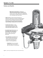
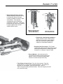
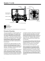
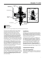
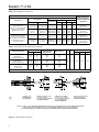
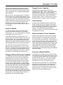
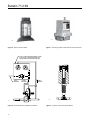
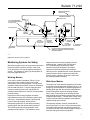
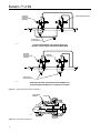
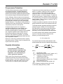
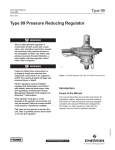
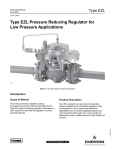
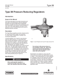
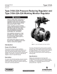
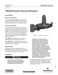
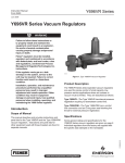
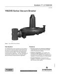
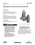
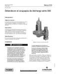
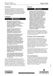
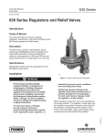
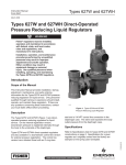
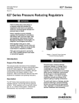
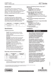
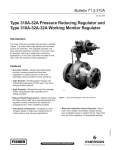
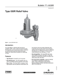
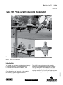
Bulletin 71.2:99
March 2012
Type 99 Pressure Reducing Regulator
W6527
W2676
Figure 1. Typical Type 99 Regulator
Introduction
A Type 99 regulator has Types 61L, 61LE, and 61LD
(low pressure); Type 61H (high pressure); or
Type 61HP (extra high pressure) pilot integrally
mounted to the actuator casing as shown in Figure 1.
The Type 99 regulator can handle up to 1000 psig
/ 69.0 bar inlet pressure (the 1000 psig / 69.0 bar
regulator requires a Type 1301F pilot supply regulator
and a Type H110 pop relief valve).
www.fisherregulators.com
D100138X012
The Type 99 gas regulators provide a broad capacity
for controlled pressure ranges and capacities
in a wide variety of distribution, industrial, and
commercial applications.
Bulletin 71.2:99
Features and Benefits
• Wide Variety of Applications—Natural gas
distribution systems, gas supply to industrial boilers, furnaces, ovens, mixers, plant air service, oxygen and ammonia service, and large commercial establishments such as shopping centers and schools.
• High Accuracy—Keeps constant inlet pressures to
downstream equipment by accurately controlling distribution
system pressures at widely varying flow rates and supply
pressures for maximum efficiency and best operation,
or by eliminating the need for pressure-compensating
meters by holding a steady pressure to the meter inlet.
• No Atmospheric Bleed—Loading
pressure bleeds downstream through
pilot via downstream control line. No
bleed occurs when regulator is shut off.
• Can Handle High Inlet Pressures—Up to 1000 psig / 69.0 bar inlet pressures (the 1000 psig / 69.0 bar regulator
requires a Type 1301F pilot supply regulator and a Type H110 pop
relief valve).
• Easily Modified for Special Service—
Types 61L and 61H pilot relay parts can be replaced with special orifices and springs for fast opening, fast
closing, or monitoring applications.
• Tight Shutoff—Heavy main spring working through a lever provides a
high seat loading force for tight shutoff.
W6529
Figure 2. Typical Type 99 Regulator with Type 61L (low-pressure pilot)
2
Bulletin 71.2:99
• High-Capacity Pressure Control—
Actuator diaphragm responds quickly to downstream pressure change, causing immediate correction in main
valve position. Pilot responds simultaneously and controls final positioning of main valve. This action permits full main valve travel, resulting in higher capacity than could be
obtained without a pilot.
W0044-1
W6531
DETAIL OF TYPE 61H PILOT
SPRING CASE (REST OF
PILOT IS LIKE TYPE 61L)
DETAIL OF TYPE 61HP
PILOT CONSTRUCTION
• Economical, Labor-Saving Installation—
Supply pressure to pilot is factory-piped directly from inlet side of main regulator body, thus requiring no upstream pilot
supply line on standard installations.
• Excellent Low Flow Control—The Type 99 regulator has a wide turn-down range from very low
flow to high outlet pressures. Settings range from
2-inches w.c. to 100 psig / 5 mbar to 6.9 bar.
• Easy to Maintain—Valve disk and orifice can be inspected without removing body from pipeline. Union nut connection permits quick removal of actuator and pilot from body.
• Three Pilots to Choose From—Type 61L (low pressure), Type 61H (high pressure), or Type 61HP (extra high pressure). Two versions of the Type 61L are available, Types 61LD and 61LE. Refer to
Table 2 for approximate proportional bands. Pilots are integrally mounted to the actuator casing.
3
Bulletin 71.2:99
Specifications
Available Construction
Type 99L: Type 99 with Type 61L pilot which
has 2-inches w.c. to 20 psig / 5 mbar to 1.4 bar
pressure range.
Type 99LD: Type 99 with Type 61LD pilot which
has a narrower proportional band than the
standard Type 61L pilot.
Type 99LE: Type 99 with Type 61LE pilot which
has a broader proportional band than the
standard Type 61L pilot.
Type 99H: Type 99 with Type 61H pilot which
has 10 to 65 psig / 0.69 to 4.5 pressure range.
Type 99HP: Type 99 with Type 61HP pilot which
has 35 to 100 psig / 2.4 to 6.9 pressure range.
Body Size and End Connection Styles
NPS 2 / DN 50 body with NPT, CL125 FF, CL150 RF,
CL250 RF, CL300 RF end connections
Maximum Allowable Inlet Pressure(1)
160 psig / 11.0 bar: Type 61LD pilot
400 psig / 27.6 bar: Types 61L, 61LE, and 61H pilots
1000 psig / 69.0 bar: Type 61HP pilot, along with
Type 1301F pilot supply regulator and Type H110
relief valve (1/2-inch / 13 mm orifice only) See Table 3
Maximum Pilot Spring Case Pressure for
Pressure Loading(1)(2)
Types 61L, 61LD and 61LE: 50 psi / 3.4 bar
with special steel closing cap
Types 61H and 61HP: 100 psi / 6.9 bar
Outlet Pressure Ranges
See Table 1
Approximate Proportional Bands
See Table 2
Maximum Allowable Pressure Drop(1)
See Table 3
Minimum Differential Pressure Required for
Full Stroke
See Table 3
Maximum Actuator Pressures(1)
Operating: 100 psig / 6.9 bar
Emergency: 110 psig / 7.6 bar
Flow and Sizing Coefficients and Orifice Sizes
See Table 5
Typical Regulating Capacities
See Table 6
Maximum Rated Travel
1/4-inch / 6.4 mm
Temperature Capabilities(1)
With Nitrile (NBR) / Neoprene (CR) / Nylon (PA):
-20 to 180°F / -29 to 82°C
With Fluorcarbon (FKM):
0 to 300°F / -18 to 149°C
Type 99 Control Line and Pilot Connections
See Figure 13
Approximate Weight
115 pounds / 52 kg
Construction Materials
Actuator Casing: Cast iron
Pilot Body and Spring Case: Cast iron
Actuator Diaphragm: Nitrile (NBR) or
Fluorocarbon (FKM)
Upper and Lower Pilot Diaphragm
Types 61L and 61H: Nitrile (NBR) or Fluorocarbon (FKM)
Type 61HP: Neoprene (CR) or Fluorocarbon (FKM)
Main Valve Body
400 psig / 27.6 bar: Cast iron or WCC Steel
1000 psig / 69.0 bar: WCC Steel
Metal Trim Parts for Main Valve Body
400 psig / 27.6 bar: Brass or Stainless steel
1000 psig / 69.0 bar: Stainless steel
Elastomer Seats for Main Valve Body
Neoprene (CR), Nitrile (NBR), Fluorocarbon (FKM)
Nylon (PA), or Polytetrafluoroethylene (PTFE)
Metal Trim Parts for Pilot: Steel, Stainless steel,
Cast iron, Aluminum, Brass, or Zinc
Elastomer Seats for Pilot: Nitrile (NBR)
or Fluorocarbon (FKM)
Pilot Gaskets
Type 61L: Neoprene (CR)
Types 61H and 61HP: Composition
O-Rings: Nitrile (NBR) or Fluorocarbon (FKM)
P590 Series Filter
Type P594-1: Brass
Type P593-1: Aluminum
Replaceable Filter: Cellulose
Tubing and Fittings
Copper or Stainless steel tubing and Brass, Steel,
or Stainless steel fittings
Type 1301F Pilot Supply Regulator
Body and Spring Case: Brass
Valve Disk: Nylon (PA) / PTFE
Gasket: Neoprene (CR)
Metal Trim Parts: Brass or Stainless steel
Type H110 Pop Relief Valve
Body: Brass
Disk: Nitrile (NBR)
Spring: Stainless steel
Additional Options
• 1000 psig / 69.0 bar Inlet Pressure Regulator
• O-Ring Stem Seal for Upstream Regulator • Travel Indicator • Electronic Remote Control Capability
• Handwheel for Type 61L Pilot
1. The pressure/temperature limits in this Bulletin and any applicable standard or code limitation should not be exceeded.
2. For stability or overpressure protection, a pilot supply regulator may be installed in the pilot supply tubing between the main valve and pilot.
4
Bulletin 71.2:99
Table 1. Outlet Pressure Ranges
Pilot
type
MAXIMUM PILOT
SUPPLY PRESSURE
psig
Pilot Control Spring
Outlet Pressure Ranges
bar
psig
bar
2 to 4-inches w.c.(1)
3 to 12-inches w.c.(1)
0.25 to 2
1 to 5
2 to 10
5 to 15
10 to 20
5 to 10 mbar(1)
7 to 30 mbar(1)
0.02 to 0.14
0.07 to 0.35
0.14 to 0.69
0.35 to 1.0
0.69 to 1.4
61L
400
27.6
61LD
160
11.0
61LE
400
27.6
Part Number
Color Code
1B558527052
1C680627222
1B886327022
1J857827022
1B886427022
1J857927142
1B886527022
Orange
Unpainted
Red
Yellow
Blue
Brown
Green
Wire Diameter
Free Length
Inches
mm
Inches
mm
0.072
0.080
0.109
0.142
0.172
0.187
0.207
1.83
2.03
2.77
3.61
4.37
4.75
5.26
3.78
3.00
2.75
2.75
2.88
3.03
3.13
96.0
76.2
69.9
69.9
73.2
77.0
79.5
61H
400
27.6
10 to 65
0.69 to 4.5
0Y066427022
Green stripe
0.363
9.22
6.00
152
61HP
600
41.4
35 to 100
2.4 to 6.9
1D387227022
Blue
0.200
5.08
1.69
42.9
1. Type 61LD pilot only.
Table 2. Approximate Proportional Bands
PILOT CONTROL SPRING
PILOT TYPEs
Part Number
Color Code
61LD
1B558527052
1C680627222
Orange
Unpainted
Wire Diameter
PROPORTIONAL BANDS
Free Length
Inches
mm
Inches
mm
Inches w.c.
mbar
0.075
0.080
1.91
2.03
4.13
3.25
105
82.6
0.1 to 0.5
0.25 to 1
61L
1B886327022
Red
0.109
2.77
2.75
69.9
1 to 2
2 to 5
61LD
1B886327022
Red
0.109
2.77
2.75
69.9
0.25 to 1
0.62 to 2
61LE
1B886327022
Red
0.109
2.77
2.75
69.9
5 to 8
12 to 20
61L, 61LD, and 61LE
1J857827022
1B886427022
1J857927142
1B886527022
Yellow
Blue
Brown
Green
0.142
0.172
0.187
0.207
3.61
4.37
4.75
5.26
2.75
2.88
2.88
3.13
69.9
73.2
73.2
79.5
0.1 to 0.3 psi
0.01 to 0.02 bar
61H
0Y066427022
Green stripe
0.363
9.22
6.00
152
0.1 to 0.3 psi
0.01 to 0.02 bar
61HP
1D387227022
Blue
0.200
5.08
1.69
42.9
1 to 2 psi
0.07 to 0.14 bar
disk MATERIALs
MAXIMUM
ORIFICE
SIZE(1)(5)
Table 3. Maximum Inlet Pressure, Allowable Pressure Drop, and Minimum Differential Pressures
MAXIMUM
ALLOWABLE
Inlet Pressure
/ Pressure
Drop
psig
MAIN VALVE SPRING
Part
Number
bar
Wire Diameter
Inches
mm
Free Length
Inches
mm
MINIMUM
DIFFERENTIAL
PRESSURE FOR FULL
STROKE
psig
bar
Inches
mm
1-1/8
29
25
1.7
1C277127022
0.148
3.76
6
152
0.75
0.05
Nitrile Disk Type Option (NBR) and
Fluorocarbon (FKM)
50
3.4
1N801927022
0.156
3.96
7.13
181
1.5
0.10
Neoprene (CR) and Fluorocarbon (FKM)
1-1/8
29
150
10.3
1B883327022
0.187
4.75
6.63
168
3
0.21
Nitrile O-ring Type Option (NBR),
Neoprene (CR), and Fluorocarbon (FKM)
1-1/8
29
175(2)
12.1(2)
1B883327022
0.187
4.75
6.63
168
3
0.21
Nitrile O-ring Type Option (NBR),
Neoprene (CR), and Fluorocarbon (FKM)
7/8
22
250
17.2
1B883327022
0.187
4.75
6.63
168
3
0.21
Neoprene (CR) and Fluorocarbon (FKM)
7/8
22
0.69
Nylon (PA)
1-1/8(3)
29(3)
300
20.7
400
27.6
0W019127022
0.281
7.22
6
152
10
0.69
Nylon (PA) and PTFE
7/8
22
1000
69.0
0W019127022
0.281
7.22
6
152
10
0.69
Nylon (PA)
1/2(4)
13(4)
1.
2.
3.
4.
5.
0W019127022
0.281
7.22
6
152
10
C
an use all orifice sizes up to maximum size listed. See Table 5.
CL125 FF flanged body only.
1-1/8-inch / 29 mm is the only orifice available for 300 psig / 20.7 bar maximum inlet pressure regulator.
1/2-inch / 13 mm is the only orifice available for 1000 psig / 69.0 bar maximum inlet pressure regulator.
O-ring seat construction is only available for 7/8 and 1-1/8-inch / 22 and 29 mm orifice sizes.
5
Bulletin 71.2:99
outlet pipe
bleed valve
bleed orifice
main valve spring
main diaphragm
pusher post assembly
pilot diaphragm assembly
inlet
pilot diaphragm
pilot orifice
pilot control spring
A6469
inlet pressure
outlet pressure
atmospheric pressure
loading pressure
Figure 3. Schematic of Type 99 Regulator with Type 61L (Low Pressure) Pilot
Principle of Operation
The key to the operation of a Type 99 regulator is the
yoked double-diaphragm pilot. Fast response and
accuracy are made possible by the amplifying effect
of the pressure-balanced pilot and by the two-path
control system. The function of the pilot is to sense
change in the controlled pressure and amplify it into a
larger change in the loading pressure. Any changes
in outlet pressure act quickly on both the actuator
diaphragm and the loading pilot, thus providing the
precise pressure control that is a characteristic of a
two-path system.
A typical pilot has an approximate gain of 20, which
means the outlet pressure needs to droop only 1/20
as much as a direct-operated regulator in order to
obtain the same pressure differences across the main
diaphragm. Advantages of a pilot-operated regulator
are high accuracy and high capacity.
Upstream or inlet pressure is utilized as the operating
medium, which is reduced through pilot operation to
load the main diaphragm chamber. Tubing connects
the inlet pressure to the pilot through a filter assembly.
Downstream or outlet pressure registers underneath the
main diaphragm through the downstream control line.
6
In operation, assume the outlet pressure is less than
the setting of the pilot control spring. The top side
of the pilot diaphragm assembly will have a lower
pressure than the setting of the spring. Spring forces
the diaphragm head assembly upward, opening the
relay or inlet orifice. Additional loading pressure is
supplied to the pilot body and to the top side of the
main diaphragm.
This creates a higher pressure on the top side of the
main diaphragm than on the bottom side, forcing the
diaphragm downward. This motion is transmitted
through a lever, which pulls the valve disk open,
allowing more gas to flow through the valve.
When the gas demand in the downstream system
has been satisfied, the outlet pressure increases.
The increased pressure is transmitted through the
downstream control line and acts on top of the pilot
diaphragm head assembly. This pressure exceeds
the pilot spring setting and forces the head assembly
down, closing orifice. The loading pressure acting on
main diaphragm bleeds to the downstream system
through a small slot between the pilot bleed valve and
bleed orifice.
Bulletin 71.2:99
downstream
control line
main valve
spring
bleed
orifice
main diaphragm
relief
valve
cap
bleed
valve
relief
valve
body
diaphragm
yoke
cap
pusher post
assembly
yoke
leg
yoke
cap
flange
adaptor
pilot diaphragm
54A2767-a
orifice
relay
valve
inlet pressure
tubing connection
pilot spring
inlet pressure
outlet pressure
atmospheric pressure
loading pressure
Figure 4. Schematic of Type 99 Regulator with Type 61HP (Extra High Pressure) Pilot
Normally, excess loading pressure slowly escapes
downstream around the bleed valve (Figure 3) or
through the relief valve body (Figure 4). Since
loading pressure needs to exceed outlet pressure
only moderately to stroke the main valve fully open,
a continued increase in loading pressure differential
extends the main diaphragm and the pusher post
assembly far enough to separate the bleed valve and
the bleed orifice. This action permits quick dumping of
excess loading pressure into the downstream system.
With a decrease in loading pressure on top of the
main diaphragm, the main spring exerts an upward
force on the diaphragm rod connected to the main
diaphragm, pulling it in an upwards direction. This
moves the main valve towards its seat, decreasing
the flow to the downstream system.
The pilot valve diaphragm acts as a sealing member
for the loading chamber and as a balancing member
to the upper pilot diaphragm. These two diaphragms
are connected by a yoke so any pressure change in
the pilot chamber has little effect on the position of the
pilot valve. Therefore, the active diaphragm in the pilot
is the upper pilot diaphragm and the pressure on the
top side of this diaphragm opposes the force of the
pilot control spring.
Installation
Although the union nut permits the actuator and pilot
to be mounted in any position relative to the body, the
typical installation is with the body in a horizontal run
of pipe and the pilot hanging vertically from the bottom
of the actuator as shown in Figure 1.
Control and vent lines necessary for installation are
not supplied with a Type 99 regulator. Control and
vent connection locations are shown in Figures 13 to
15. In most applications, good piping practices will
require that the outlet piping be swaged up a size
above the body size to prevent excessive pressure
drop along the outlet line. The piping should be
expanded as close to the regulator outlet as possible.
Dimensional information also is given in Figures 13 to 15.
Construction Features
Pilot Interchangeability
When higher or lower pressure control is required, the
existing pilot can be changed to one that provides the
desired range.
7
Bulletin 71.2:99
Table 4. Working Monitor Performance
MONITORING PILOT INFORMATION
Pilot Spring
Spring Range
Construction
Type 161AYW with
1/8-inch / 3.2 mm orifice size and
150 psig / 10.3 bar maximum
allowable inlet pressure
3/4 NPT Type 627-109 with
1/8-inch / 3.2 mm orifice size
and 1000 psig / 69.0 bar maximum
inlet pressure / body rating
for ductile iron body
psig
bar
3 to 12-inches w.c.
11 to 25-inches w.c.
7 to 30 mbar
27 to 62 mbar
0.9 to 2.5
2.5 to 4.5
4.5 to 7
Part Number
Wire Diameter
Free Length
MINIMUM PRESSURE
AT WHICH WORKING
MONITOR REGULATOR
CAN BE SET
Inches
mm
Inches
mm
1B653927022
1B537027052
0.105
0.114
2.67
2.90
3.750
4.312
95.2
109
3-inches w.c. / 7 mbar
over normal
distribution pressure
0.06 to 0.17
0.17 to 0.31
0.31 to 0.48
1B537127022
1B537227022
1B537327052
0.156
0.187
0.218
3.96
4.75
5.54
4.060
3.937
3.980
103
100
101
0.5 psi / 0.03 bar
over normal
distribution pressure
5 to 20
15 to 40
0.34 to 1.4
1.0 to 2.8
10B3076X012
10B3077X012
0.170
0.207
4.32
5.26
3.190
3.190
81.0
81.0
3.0 psi / 0.21 bar
over normal
distribution pressure
35 to 80
70 to 150
2.1 to 5.5
4.8 to 10.3
10B3078X012
10B3079X012
0.262
0.313
6.65
7.95
3.200
3.070
81.3
78.0
5.0 psi / 0.34 bar
over normal
distribution pressure
Table 5. Orifice Sizes and Flow and Sizing Coefficients
ORIFICE SIZE
INCHES
mm
FOR RELIEF SIZING
WIDE-OPEN Cg
REGULATING Cg
Restricted capacity trim,
Straight bore —
Elastomer disk seat only
1/2(1)
3/4
13(1)
19
200
425
155
330
Restricted capacity trim,
Stepped bore —
Elastomer disk seat only
7/8 x 3/8
7/8 x 1/2
7/8 x 5/8
22 x 9.5
22 x 13
22 x 16
115
200
300
110
190
280
Full capacity trim,
Elastomer disk,
or O-ring seats
7/8
1-1/8
22
29
550
850
408
680
TRIM CONSTRUCTION
C1
Km
35
0.79
IEC SIZING COEFFICIENTS
XT
FD
FL
0.78
0.50
0.89
1. 1/2-inch / 13 mm is the only orifice size available for 1000 psig / 69.0 bar maximum inlet pressure.
orifice
diameter
1C3947-D
1N8781-D
14A8369-A
W6799
typical of 1/2(1)
RESTRICTED DISK
SEAT DIAMETER
orifice
diameter
TYPICAL OF 7/8-INCH / 22 mm,
1-INCH / 25 mm, AND
1-1/8-INCH / 29 mm RESTRICTED
DISK SEAT DIAMETERS
outlet
orifice
diameter
inlet orifice
diameter
TYPICAL OF 7/8 x 3/8-INCH /
22 x 9.5 mm, 7/8 x 1/2-INCH /
22 x 13 mm, AND 7/8 x 5/8-INCH /
22 x 16 mm RESTRICTED
DISK SEAT DIAMETERS(2)
TYPICAL OF 7/8-INCH / 22 mm
AND 1-1/8-INCH / 29 mm
O-RING SEAT DIAMETERS
Notes: (1) 1/2-inch / 13 mm orifice size can be used with Type 61HP pilot along with Type 1301F pilot supply regulator and Type H110 relief valve to obtain 1000 psig / 69.0 bar maximum inlet pressure to the Type 99 Main Valve.
(2) For Stepped orifices, the size of the orifice outlet diameter affects the maximum inlet pressure.
Figure 5. Type 99 Orifice Construction
8
Bulletin 71.2:99
Type 99 lower castings accept either low or high
pressure pilots without requiring separate mounting
parts for each construction. When converting to an
extra high pressure unit, an additional flange adapter
will be required.
When a Type 61L (low pressure) pilot is ordered for
field conversion to a Type 61H (high pressure) pilot
or vice versa, the replacement pilot assembly comes
complete with a pilot cover that must be removed
before installing the replacement pilot on the existing
regulator. The cover can then be installed on the
removed pilot to form a complete Type 61L (low
pressure) pilot or Type 61H (high pressure) pilot for
use elsewhere.
Choice of Shutoff
The Type 99 regulator body comes with either an
elastomer disk that seats against a knife-edged
orifice (Figure 3, 4, or 5), or an elastomer O-ring that
seats against a flat orifice (Figure 5).
O-ring seats should be used when heavier main
springs, larger orifice sizes and higher inlet pressures
are encountered. The O-ring adapter will also seat
against the orifice face creating a mechanical stop,
where the knife-edged orifice can possibly cut through
a disk damaging the seat and losing a tight shutoff.
The 1000 psig / 69.0 bar maximum inlet pressure
regulator comes standard with a 1/2-inch / 13 mm
disk seat. The lower inlet Type 99 regulators have a
choice of three different restricted-diameter orifices
and five different straight-bore orifices for unusually
light loads or for minimizing relief requirements.
1000 psig / 69.0 bar Inlet Pressure Capability
The 1000 psig / 69.0 bar maximum inlet pressure
regulator must have its Type H110 pop relief valve
installed directly, or remotely by means of piping
and an internal threaded coupling, into the 1/4 NPT
side outlet of the supply regulator. The pilot supply
regulator reduces inlet pressure to a usable 200 psig /
13.8 bar for the integral Type 61HP (extra high pressure)
pilot. The relief valve is set to relieve if the reduced
pressure from the pilot supply regulator exceeds
225 psig / 15.5 bar. This Type 99 regulator comes
standard with O-ring seals on the guide bushing and
the valve carrier assembly to keep the main valve body
outlet pressure from interfering with outlet pressure
registration in the lower actuator casing.
Rugged Service Capability
High-temperature elastomers provide service
capabilities up to 300°F / 149°C. Optional brass body
and fluorocarbon (FKM) seat can be provided for
special service requirements. Optional stainless steel
trims and an aluminum filter can be ordered where
hydrogen sulfide or other contaminants are present in
the gas and where no brass or copper is permitted.
Travel Indicator
An optional travel indicator (Figure 6) consists of an
actuator spring case with an integrally cast indicator
housing, an indicator disk enclosed in a clear housing,
and an indicator plate graduated in percent of valve
opening. This indicator assembly provides the
capability to inspect for smooth travel without removing
the regulator from service.
Electronic Remote Control Capability
When remote adjustment of the pilot control spring
setting is desired, the Type 662 remote control pilot
drive units (Figure 7) are available. This Type 662
unit mounts to the pilot and accept a variety of electrical
inputs. The Type 662 remote control pilot drive unit
uses electronic signals to switch its motor on and off. This
motor, which turns the pilot adjusting screw, changes the
spring compression to increase or decrease the pilot’s
outlet pressure. The design provides a smooth, highly
accurate positioning with a positive locking force when the
unit is not in motion.
Pressure Loading Flexibility
Type 99 pilot spring cases can be pressure loaded
for applications involving differential pressure control
or remote pneumatic adjustment of the downstream
pressure setting (Figure 8). If the system loading
pressure fails, the pilot’s outlet pressure will be
maintained by the pilot control spring setting.
Type 99 pilots are provided with a 1/4 NPT tapped
connection in the spring case. Low pressure pilots
additionally can be furnished with a handwheel
(Figure 9) for precise manual trimming of the final
pressure setting. Outlet pressure is the sum of the
spring setting and the loading pressure.
9
Bulletin 71.2:99
W6532
W2681
Figure 6. Optional Travel Indicator
Figure 7. Optional Type 662 Jordan Remote Control Pilot Drive
670 OR 671 SERIES TWO-GAUGE MANUAL LOADER
(ALSO TYPICAL OF ONE-GAUGE LOADER THAT
DISPLAYS REMOTE LOADING PRESSURE ONLY)
IN
SUPPLY
PRESSURE
EA
SE
CR
LOADING
PRESSURE
SENSED
PRESSURE
A6533
A1899
Figure 8. Pneumatic Remote Adjustment Installation
10
Figure 9. Type 61L (Low Pressure) Handwheel
Bulletin 71.2:99
DISTRIBUTION PRESSURE
CONTROL LINE
INTERMEDIATE PRESSURE
CONTROL LINE
TYPE 161AYW MONITORING
PILOT (ALSO REPRESENTATIVE
OF TYPE 627-109)
WORKING
MONITOR PILOT
PILOT SUPPLY LINE
LOADING
PRESSURE
INTERMEDIATE
PRESSURE
OPTIONAL
PILOT SUPPLY
REGULATOR
UPSTREAM
PRESSURE
WORKING
MONITOR
REGULATOR
WORKING
REGULATOR
OPTIONAL
PILOT SUPPLY
REGULATOR
DISTRIBUTION
PRESSURE
PILOT SUPPLY PIPING FOR WORKING REGULATOR
WHEN PILOT IS REqUIRED TO BE SUPPLIED FROM
UPSTREAM PRESSURE
20A1389-A
Figure 10. Working Monitor Installation
Monitoring Systems for Safety
Monitoring regulators serve as overpressure protection
devices to limit the system’s pressure in the event
of an open failure of a working regulator feeding the
system. Two methods of using Type 99 regulators in
monitoring applications are:
Working Monitor
On a working monitor installation (Figure 10), the
control line of the monitoring pilot is connected
downstream of the working regulator. During normal
operation, distribution pressure causes the monitoring
pilot to stand wide open. Full pilot supply pressure
enters the working monitor pilot and permits the
working monitor regulator to control at its intermediate
pressure setting.
Open failure of the working regulator increases
intermediate pressure as the working regulator goes
wide open. Intermediate pressure is then ignored
by the monitoring regulator, which controls
downstream pressure at its own pressure setting
(slightly higher than the normal control pressure).
The monitoring pilot should be upstream of the
working monitor regulator. This enables a closer
setpoint between the working regulator and the
monitoring pilot. Special Types 161AYW and
627-109 monitoring pilots with quick-bleed
operation have been designed to give faster
response to abnormal downstream conditions.
Table 4 gives the spread between normal distribution
pressure and the minimum pressure at which the
working monitor regulator can be set to take over if
the working regulator fails open.
Wide-Open Monitor
The control line of the upstream regulator is connected
to the outlet of the downstream regulator (Figure 11), so
that during normal operation the monitoring regulator is
standing wide open with the reduction to downstream
pressure being taken across the working regulator.
Only in case of open failure of the working regulator
does the wide-open monitoring regulator take control at
its slightly higher setting. The wide-open monitor setup
may be used with either the upstream or downstream
regulator acting as the monitor.
The upstream regulator must be ordered with an
O-ring seal (Figure 12) on the valve carrier assembly.
This seals off the leak path that otherwise would let
line pressure ahead of the working regulator inlet try to
close the wide-open monitoring regulator.
11
Bulletin 71.2:99
upstream
regulator
(requires o-ring
stem seal)
downstream regulator
optional pilot
supply regulator
10A1386-A
Flexible arrangement that permits wide-open
monitor to be either upstream or downstream
upstream
regulator
(requires o-ring
stem seal)
Working
regulator
optional pilot
supply regulator
10A1388-A
Minimum Piping Wide-Open Monitor Arrangement that
requires Wide-Open Monitor to always be Upstream
Figure 11. Typical Wide-Open Monitor Installations
valve carrier
assembly
20A7148-C
Figure 12. O-Ring Seal Construction
12
o-rings
Bulletin 71.2:99
Overpressure Protection
The Type 99 has outlet pressure ratings lower than
the inlet pressure ratings. Complete downstream
overpressure protection is required if the actual inlet
pressure can exceed the regulator outlet pressure rating
or the pressure ratings of any downstream equipment.
On the 1000 psig / 69.0 bar maximum inlet pressure
regulator, the Type H110 relief valve provides sufficient
relief capacity to protect the Type 61HP (extra high
pressure) pilot in case the Type 1301F pilot supply
regulator fails open. This pressure relief protection is
insufficient if the main valve fails open. Downstream
overpressure protection is still required.
Overpressuring any portion of a regulator or
associated equipment may cause leakage, part
damage, or personal injury due to bursting of
pressure-containing parts or explosion of accumulated
gas. Regulator operation within ratings does not
preclude the possibility of damage from external
sources or from debris in the pipeline. A regulator
should be inspected for damage periodically and after
any overpressure condition.
Refer to the relief sizing coefficients and the capacity
information section in Tables 5 and 6 to determine the
required relief valve capacity.
Capacity Information
Note
Flow capacities are laboratory
verified; therefore, regulators may
be sized for 100% flow published
capacities. It is not necessary to
reduce published capacities.
Table 6 gives Type 99 natural gas regulating
capacities at selected inlet pressures and outlet
pressure settings. Flows are in thousands of scfh
(at 60°F and 14.7 psia) and of Nm3/h (at 0°C and
1.01325 bar) of 0.6 specific gravity natural gas.
To determine equivalent capacities for air, propane,
butane, or nitrogen, multiply the scfh capacity
values in Table 6 by the following appropriate
conversion factor: 0.775 for air, 0.628 for propane,
0.548 for butane, or 0.789 for nitrogen. For gases of
other specific gravities, multiply the given capacity by
0.775 and divide by the square root of the appropriate
specific gravity. Then, if capacity is desired in Nm3/h,
multiply SCFH by 0.0268.
To obtain the published capacities, the inlet and outlet
piping should be the same as the regulator body size.
To find approximate regulating capacities at pressure
settings not given in Table 6 or to find wide-open
flow capacities for relief sizing at any inlet pressure,
perform one of the following procedures. Then, if
necessary, convert using the factors provided above.
For critical pressure drops (absolute outlet pressure
equal to or less than one-half of absolute inlet
pressure), use the following formula:
Q = (P1abs)(Cg)(1.29)
For pressure drops lower than critical (absolute outlet
pressure greater than one-half of absolute inlet pressure).
Q =
520 3417
CgP1absSIN
GT
C1
P
P1abs
DEG
where,
Q
P1abs
Cg
G
T
C1
P
= gas flow rate, scfh
= absolute inlet pressure, psia (P1 gauge + 14.7)
= regulating or wide-open gas sizing
coefficient from Table 5
= specific gravity of the gas
= absolute temperature of gas at inlet, °Rankine
= flow coefficient (Cg/Cv)
= pressure drop across the regulator, psi
Then, if capacity is desired in Nm3/h at 0°C and
1.01325 bar, multiply SCFH by 0.0268.
13
Bulletin 71.2:99
Table 6. Capacities of Type 99 Regulators (Full Capacity)
ORIFICE
SIZE
INLET
PRESSURE
CAPACITIES(1) IN THOUSANDS OF SCFH / Nm3/h OF 0.6 SPECIFIC GRAVITY NATURAL GAS(2)
Outlet Pressure, psig / bar
INCHES mm psig
7/8
1-1/8
22
29
bar
0.25 / 0.02
SCFH
Nm3/h
0.5 / 0.03
SCFH
Nm3/h
1 / 0.07
SCFH
Nm3/h
2 / 0.14
SCFH
Nm3/h
3 / 0.21
4 / 0.28
SCFH
Nm3/h
5 / 0.34
SCFH
Nm3/h
SCFH
Nm3/h
6 / 0.41
SCFH
Nm3/h
SCFH
Nm3/h
8 / 0.55
9 / 0.62
SCFH
Nm3/h
SCFH
Nm3/h
10 / 0.69
SCFH Nm3/h
5
6
7
8
9
0.35
0.41
0.48
0.55
0.62
7.2
7.8
9.0
9.6
10
0.2
0.2
0.2
0.3
0.3
7.2
7.8
9.0
9.6
10
0.2
0.2
0.2
0.3
0.3
6.6
7.8
9.0
9.6
10
0.2
0.2
0.2
0.3
0.3
6.6
7.8
9.0
9.6
10
0.2
0.2
0.2
0.3
0.3
6.6
7.2
7.8
9
--0.2
0.2
0.2
0.2
6.6
7.2
8.4
----0.2
0.2
0.2
6.6
7.2
------0.2
0.2
6.6
--------0.2
10
15
20
25
30
0.69
1.0
1.4
1.7
2.1
11.4
14.4
18.6
21
23
0.3
0.4
0.5
0.6
0.6
11.4
14.4
18.6
21
23
0.3
0.4
0.5
0.6
0.6
10.8
14.4
18.6
21
23
0.3
0.4
0.5
0.6
0.6
10
14.4
18.6
21
23
0.3
0.4
0.5
0.6
0.6
9.6
14.4
18.6
21
23
0.3
0.4
0.5
0.6
0.6
9.0
13.8
18.6
21
23
0.2
0.4
0.5
0.6
0.6
8.4
13.2
18
21
23
0.2
0.4
0.5
0.6
0.6
7.8
13.2
16.8
21
23
0.2
0.4
0.5
0.6
0.6
7.2
12
16.2
21
23
0.2
0.3
0.4
0.6
0.6
12
15.6
19.8
23
--0.3
0.4
0.5
0.6
-11.4
15
19.8
23
-0.3
0.4
0.5
0.6
-7.8
14.4
19.2
23
-0.2
0.4
0.5
0.6
35
40
50
60
75
2.4
2.8
3.4
4.1
5.2
26
28
34
42
47
0.7
0.8
0.9
1.1
1.3
26
28
34
42
47
0.7
0.8
0.9
1.1
1.3
26
28
34
42
47
0.7
0.8
0.9
1.1
1.3
26
28
34
42
47
0.7
0.8
0.9
1.1
1.3
26
28
34
42
47
0.7
0.8
0.9
1.1
1.3
26
28
34
42
47
0.7
0.8
0.9
1.1
1.3
26
28
34
42
47
0.7
0.8
0.9
1.1
1.3
26
28
34
42
47
0.7
0.8
0.9
1.1
1.3
26
28
34
42
47
0.7
0.8
0.9
1.1
1.3
26
28
34
42
47
0.7
0.8
0.9
1.1
1.3
26
28
34
42
47
0.7
0.8
0.9
1.1
1.3
26
28
34
42
47
0.7
0.8
0.9
1.1
1.3
100
125
150
175
200
6.9
8.6
10.3
12.1
13.8
59
73
86
96
108
1.6
2.0
2.3
2.6
2.9
59
73
86
96
108
1.6
2.0
2.3
2.6
2.9
59
73
86
96
108
1.6
2.0
2.3
2.6
2.9
59
73
86
96
108
1.6
2.0
2.3
2.6
2.9
59
73
86
96
108
1.6
2.0
2.3
2.6
2.9
59
73
86
96
108
1.6
2.0
2.3
2.6
2.9
59
73
86
96
108
1.6
2.0
2.3
2.6
2.9
59
73
86
96
108
1.6
2.0
2.3
2.6
2.9
59
73
86
96
108
1.6
2.0
2.3
2.6
2.9
59
73
86
96
108
1.6
2.0
2.3
2.6
2.9
59
73
86
96
108
1.6
2.0
2.3
2.6
2.9
59
73
86
96
108
1.6
2.0
2.3
2.6
2.9
225
250
300
350
400
15.5
17.2
20.7
24.1
27.6
123
132
162
188
215
3.3
3.5
4.3
5.0
5.8
123
132
162
188
215
3.3
3.5
4.3
5.0
5.8
123
132
162
188
215
3.3
3.5
4.3
5.0
5.8
123
132
162
188
215
3.3
3.5
4.3
5.0
5.8
123
132
162
188
215
3.3
3.5
4.3
5.0
5.8
123
132
162
188
215
3.3
3.5
4.3
5.0
5.8
123
132
162
188
215
3.3
3.5
4.3
5.0
5.8
123
132
162
188
215
3.3
3.5
4.3
5.0
5.8
123
132
162
188
215
3.3
3.5
4.3
5.0
5.8
123
132
162
188
215
3.3
3.5
4.3
5.0
5.8
123
132
162
188
215
3.3
3.5
4.3
5.0
5.8
123
132
162
188
215
3.3
3.5
4.3
5.0
5.8
1
2
3
4
5
0.07
0.14
0.21
0.28
0.35
5
7.5
9
10
12
0.1(2)
0.2(2)
0.2
0.3
0.3
7.5
9
10
12
--0.2(2)
0.2
0.3
0.3
6
8.5
10
12
--0.2(2)
0.2(2)
0.3
0.3
8.5
10
------0.2(2)
0.3
9
--------0.2(2)
6
7
8
9
10
0.41
0.48
0.55
0.62
0.69
13
15
16
17
19
0.3
0.4
0.4
0.5
0.5
13
15
16
17
19
0.3
0.4
0.4
0.5
0.5
13
15
16
17
19
0.3
0.4
0.4
0.5
0.5
12
13
14
16
17
0.3
0.3
0.4
0.4
0.5
10
12
13
15
16
0.3
0.3
0.3
0.4
0.4
9
10
12
14
15
0.2(2)
0.3
0.3
0.4
0.4
9
11
12
14
--0.2(2)
0.3
0.3
0.4
9
11
13
----0.2(2)
0.3
0.3
10
12
------0.3(2)
0.3
10
--------0.3(2)
15
20
25
30
35
1.0
1.4
1.7
2.1
2.4
24
31
35
39
44
0.6
0.8
0.9
1.0
1.2
24
31
35
39
44
0.6
0.8
0.9
1.0
1.2
24
31
35
39
44
0.6
0.8
0.9
1.0
1.2
24
31
35
39
44
0.6
0.8
0.9
1.0
1.2
24
31
35
39
44
0.6
0.8
0.9
1.0
1.2
23
31
35
39
44
0.6
0.8
0.9
1.0
1.2
22
30
35
39
44
0.6
0.8
0.9
1.0
1.2
22
30
35
39
44
0.6
0.8
0.9
1.0
1.2
20
27
35
39
44
0.5
0.7
0.9
1.0
1.2
20
26
33
39
44
0.5
0.7
0.9
1.0
1.2
19
25
33
39
44
0.5
0.7
0.9
1.0
1.2
13
24
32
39
44
0.4
0.6
0.9
1.0
1.2
40
50
60
75
2.8
3.4
4.2
5.2
47
57
65
78
1.3
1.5
1.7
2.1
47
57
65
78
1.3
1.5
1.7
2.1
47
57
65
78
1.3
1.5
1.7
2.1
47
57
65
78
1.3
1.5
1.7
2.1
47
57
65
78
1.3
1.5
1.7
2.1
47
57
65
78
1.3
1.5
1.7
2.1
47
57
65
78
1.3
1.5
1.7
2.1
47
57
65
78
1.3
1.5
1.7
2.1
47
57
65
78
1.3
1.5
1.7
2.1
47
57
65
78
1.3
1.5
1.7
2.1
47
57
65
78
1.3
1.5
1.7
2.1
47
57
65
78
1.3
1.5
1.7
2.1
100
125
150
175
6.9
8.6
10.3
12.1
99
122
143
160
2.7
3.3
3.8
4.3
99
122
143
160
2.7
3.3
3.8
4.3
99
122
143
160
2.7
3.3
3.8
4.3
99
122
143
160
2.7
3.3
3.8
4.3
99
122
143
160
2.7
3.3
3.8
4.3
99
122
143
160
2.7
3.3
3.8
4.3
99
122
143
160
2.7
3.3
3.8
4.3
99
122
143
160
2.7
3.3
3.8
4.3
99
122
143
160
2.7
3.3
3.8
4.3
99
122
143
160
2.7
3.3
3.8
4.3
99
122
143
160
2.7
3.3
3.8
4.3
99
122
143
160
2.7
3.3
3.8
4.3
200
225
250
300
13.8
15.5
17.2
20.7
180
205
220
265
4.8
5.5
5.9
7.1
180
205
220
265
4.8
5.5
5.9
7.1
180
205
220
265
4.8
5.5
5.9
7.1
180
205
220
265
4.8
5.5
5.9
7.1
180
205
220
265
4.8
5.5
5.9
7.1
180
205
220
265
4.8
5.5
5.9
7.1
180
205
220
265
4.8
5.5
5.9
7.1
180
205
220
265
4.8
5.5
5.9
7.1
180
205
220
265
4.8
5.5
5.9
7.1
180
205
220
265
4.8
5.5
5.9
7.1
180
205
220
265
4.8
5.5
5.9
7.1
180
205
220
265
4.8
5.5
5.9
7.1
Type 61L
Pilot
1. When sizing a regulator, always use the lowest inlet pressure, the highest outlet pressure, and the maximum capacity desired.
2. Requires 0.75 psig / 0.05 bar minimum differential pressure construction.
Black areas show no capacity due to differential pressure requirement.
14
7 / 0.48
Bulletin 71.2:99
Table 6. Capacities of Type 99 Regulators (Full Capacity) (continued)
ORIFICE SIZE
INLET
PRESSURE
CAPACITIES(1) IN THOUSANDS OF SCFH / Nm3/h OF 0.6 SPECIFIC GRAVITY NATURAL GAS(2)
Outlet Pressure, psig / bar
INCHES mm psig
bar
15 / 1.0
20 / 1.4
25 / 1.7
30 / 2.1
35 / 2.4
40 / 2.8
45 / 3.1
50 / 3.5
60 / 4.1
75 / 5.2
100 / 6.9
SCFH Nm3/h SCFH Nm3/h SCFH Nm3/h SCFH Nm3/h SCFH Nm3/h SCFH Nm3/h SCFH Nm3/h SCFH Nm3/h SCFH Nm3/h SCFH Nm3/h SCFH Nm3/h
7/8
1-1/8
22
29
5
6
7
8
9
0.34
0.41
0.48
0.55
0.62
10
15
20
25
30
0.69
1.0
1.4
1.7
2.1
10.8
16.2
20
----0.3
0.4
0.5
12
17
------0.3
0.5
12.5
--------0.3
35
40
50
60
75
2.4
2.8
3.4
4.1
5.2
24
28
34
42
47
0.6
0.8
0.9
1.1
1.3
21
26
34
42
47
0.6
0.7
0.9
1.1
1.3
18
23
31
42
47
0.5
0.6
0.8
1.1
1.3
13
19
28
37
47
0.3
0.5
0.8
1.0
1.3
14.4
25
35
47
--0.4
0.7
0.9
1.3
21
30
45
----0.6
0.8
1.2
15.5
27
41
----0.4
0.7
1.1
23
37
------0.6
1.0
30
--------0.8
100
125
150
175
200
6.9
8.6
10.3
12.1
13.8
59
73
86
96
108
1.6
2.0
2.3
2.6
2.9
59
73
86
96
108
1.6
2.0
2.3
2.6
2.9
59
73
86
96
108
1.6
2.0
2.3
2.6
2.9
59
73
86
96
108
1.6
2.0
2.3
2.6
2.9
59
73
86
96
108
1.6
2.0
2.3
2.6
2.9
59
73
86
96
108
1.6
2.0
2.3
2.6
2.9
59
73
86
96
108
1.6
2.0
2.3
2.6
2.9
59
73
86
96
108
1.6
2.0
2.3
2.6
2.9
53
73
86
96
108
1.4
2.0
2.3
2.6
2.9
44
66
86
96
108
1.2
1.8
2.3
2.6
2.9
48
72
93
108
--1.3
1.9
2.5
2.9
225
250
300
350
400
15.5
17.2
20.7
24.1
27.6
123
132
162
188
215
3.3
3.5
4.3
5.0
5.8
123
132
162
188
215
3.3
3.5
4.3
5.0
5.8
123
132
162
188
215
3.3
3.5
4.3
5.0
5.8
123
132
162
188
215
3.3
3.5
4.3
5.0
5.8
123
132
162
188
215
3.3
3.5
4.3
5.0
5.8
123
132
162
188
215
3.3
3.5
4.3
5.0
5.8
123
132
162
188
215
3.3
3.5
4.3
5.0
5.8
123
132
162
188
215
3.3
3.5
4.3
5.0
5.8
123
132
162
188
215
3.3
3.5
4.3
5.0
5.8
123
132
162
188
215
3.3
3.5
4.3
5.0
5.8
123
132
162
188
215
3.3
3.5
4.3
5.0
5.8
1
2
3
4
5
0.07
0.14
0.21
0.28
0.35
6
7
8
9
10
0.41
0.48
0.55
0.62
0.69
15
20
25
30
35
1.0
1.4
1.7
2.1
2.4
18
27
34
40
--0.5
0.7
0.9
1.1
20
28
35
----0.5
0.8
0.9
21
30
------0.6
0.8
22
--------0.6
40
50
60
75
2.8
3.4
4.2
5.2
47
57
65
78
1.3
1.5
1.7
2.1
43
57
65
78
1.2
1.5
1.7
2.1
38
52
65
78
1.0
1.4
1.7
2.1
32
47
62
78
0.9
1.3
1.7
2.1
24
42
58
78
0.6
1.1
1.6
2.1
35
50
74
--0.9
1.3
2.0
26
45
68
--0.7
1.2
1.8
38
32
----1.0
0.9
50
------1.3
100
125
150
175
6.9
8.6
10.3
12.1
99
122
143
160
2.7
3.3
3.8
4.3
99
122
143
160
2.7
3.3
3.8
4.3
99
122
143
160
2.7
3.3
3.8
4.3
99
122
143
160
2.7
3.3
3.8
4.3
99
122
143
160
2.7
3.3
3.8
4.3
99
122
143
160
2.7
3.3
3.8
4.3
99
122
143
160
2.7
3.3
3.8
4.3
99
122
143
160
2.7
3.3
3.8
4.3
99
122
143
160
2.7
3.3
3.8
4.3
88
122
143
160
2.4
3.3
3.8
4.3
80
120
155
--2.1
3.2
4.2
200
225
250
300
13.8
15.5
17.2
20.7
180
205
220
265
4.8
5.5
5.9
7.1
180
205
220
265
4.8
5.5
5.9
7.1
180
205
220
265
4.8
5.5
5.9
7.1
180
205
220
265
4.8
5.5
5.9
7.1
180
205
220
265
4.8
5.5
5.9
7.1
180
205
220
265
4.8
5.5
5.9
7.1
180
205
220
265
4.8
5.5
5.9
7.1
180
205
220
265
4.8
5.5
5.9
7.1
180
205
220
265
4.8
5.5
5.9
7.1
180
205
220
265
4.8
5.5
5.9
7.1
180
205
220
265
4.8
5.5
5.9
7.1
Type 61L
Pilot
Type 61H
Pilot
Type 61HP
Pilot
1. When sizing a regulator, always use the lowest inlet pressure, the highest outlet pressure, and the maximum capacity desired.
2. Requires 0.75 psig / 0.05 bar minimum differential pressure construction.
Black areas show no capacity due to differential pressure requirement.
15
Bulletin 71.2:99
6.12 /
155
9.62 / 244
16.88 / 429
4.75 / 121
7.25 / 184
2.12 / 54
VENT HOLE
IN CAP
1/2 NPT ALTERNATE
PLUGGED CONTROL
CONNECTION
1/4 NPT PLUGGED VENt
LOCATED 90° FROM POSITION SHOWN
10.38 /
264
A: 10.00 / 254 FOR
cl125 FF OR cl150 RF
OR 10.50 / 267 FOR
cl250 OR cl300 RF
5.25 /
133
12.25 / 311
A/2
AR5733-A
1/2 - 14 NPT
CONTROL CONNECTION
INCHES / mm
Figure 13. Type 99 (Flanged) with Type 61L Pilot Dimensions
16
Bulletin 71.2:99
6.25 /
159
PARTS DETAIL OF
1000 psig / 69.0 bar
MAXIMUM INLET
REGULATOR
1/4 NPT (internal) TAPPED SIDE OUTLET IN
TYPE 1301F PILOT SUPPLY REGULATOR
1/4 NPT CONNECTION ON
TYPE H110 POP RELIEF VALVE
6.12 /
155
12.75 /
324
9.62 / 244
18.88 / 479
9.25 / 235
MAXIMUM
1/4 NPT TAPPED
1/2 NPT
CONTROL
CONNECTION
2 NPT
10.19 /
259
5.25 / 133
3.03 /
77
6.06 /
154
12.25 /
311
1/2 NPT ALTERNATE PLUGGED
CONTROL CONNECTION
A6800
INCHES / mm
Figure 14. Type 99 (NPT) with Type 61HP Pilot Dimensions
17
Bulletin 71.2:99
13.12 /
333
6.12 /
155
9.75 / 248
21.12 / 536
15.25 / 387
1.44 / 36
1/2 NPT
ALTERNATE
PLUGGED CONTROL
CONNECTION
RAINPROOF
VENT 1/4 NPT
19.25 /
489
2 NPT
10.38 /
264
3.03 /
77
6.06 /
154
12.25 / 311
5.25 / 133
99T61
1/2 NPT CONTROL CONNECTION
INCHES / mm
Figure 15. Type 99 (NPT) with Type 61H Pilot Dimensions
Ordering Information
Use the Specifications section and carefully review
the description to the right of each specification. Use
this information to complete the Ordering Guide on
18
the next page. Specify the desired selection wherever
there is a choice to be made. Then send the Ordering
Guide to your local Sales Office.
Bulletin 71.2:99
Ordering Guide
Body Material and End Connection Style
(Select One)
NPS 2 / DN 50 Cast Iron Body
NPT***
CL125 FF***
CL250 RF***
NPS 2 / DN 50 WCC Steel Body
NPT***
CL150 RF**
CL300 RF**
SWE*
NPS 2 Brass Body
NPT**
Orifice Size (Select One)
1/2-inch / 13 mm***
3/4-inch / 19 mm***
7/8-inch / 22 mm***
1-1/8-inch / 29 mm***
7/8 x 3/8-inch / 22 x 9.53 mm*
7/8 x 1/2-inch / 22 x 13 mm**
7/8 x 5/8-inch / 22 x 16 mm**
Trim Material Main Valve and Pilot (Select One)
Brass with disk seat (standard)***
Stainless steel with disk seat**
Brass with O-ring seat
(7/8 and 1-1/8-inch / 22 and 29 mm orifice)***
Stainless steel with O-ring seat
(7/8 and 1-1/8-inch / 22 and 29 mm orifice)**
Seat Material (Select One)
Nitrile (NBR)***
Neoprene (CR)**
Nylon (PA)**
Fluorocarbon (FKM)**
PTFE**
Main Valve Spring (Select One)
Maximum Allowable Drop and Spring Part Number
25 psig / 1.72 bar, 1C277127022***
50 psig / 3.4 bar, 1N801927022***
100 psig / 6.9 bar, 1B883327022***
150 psig / 10.3 bar, 1B883327022***
175 psig / 12.1 bar, 1B883327022***
Main Valve Spring (Select One)
Maximum Allowable Drop and Spring Part Number
(continued)
250 psig / 17.2 bar, 1B883327022***
300 psig / 20.7 bar, 0W019127022**
400 psig / 27.6 bar, 0W019127022**
1000 psig / 69.0 bar, 0W019127022**
Tubing and Fittings (Select One)
Copper tubing and brass fittings (standard)***
Stainless steel tubing and steel fittings**
Stainless steel tubing and stainless
steel fittings**
Outlet Pressure Ranges (Select One)
2 to 4-inches w.c. / 5 to 10 mbar, Orange*
3 to 12-inches w.c. / 7 to 30 mbar, Unpainted***
0.25 to 2 psig / 0.02 to 0.14 bar, Red***
1 to 5 psig / 0.07 to 0.34 bar, Yellow***
2 to 10 psig / 0.14 to 0.69 bar, Blue**
5 to 15 psig / 0.34 to 1.0 bar, Brown***
10 to 20 psig / 0.69 to 1.4 bar, Green**
10 to 65 psig / 0.69 to 4.5 bar, Green stripe***
35 to 100 psig / 2.4 to 6.9 bar, Blue***
Upstream Regulator O-Ring Stem Seal (Optional)
Yes
Travel Indicator (Optional)
Yes
Electronic Remote Control Capability (Optional)
Yes
Ordering Guide (continued)
Handwheel for Type 61L Pilot (Optional)
Yes
Main Valve Parts Kit (Optional)
Yes, please send me one parts kit to match
this order.
Pilot Parts Kit (Optional)
Yes, please send me one parts kit to match
this order.
19
Bulletin 71.2:99
Specification Worksheet
Application:
Specific Use
Line Size
Gas Type and Specific Gravity
Gas Temperature
Does the Application Require Overpressure Protection?
Yes No If yes, which is preferred:
Relief Valve Monitor Regulator Shutoff Device
Is overpressure protection equipment selection assistance
desired? Pressure:
Maximum Inlet Pressure (P1max)
Minimum Inlet Pressure (P1min)
Downstream Pressure Setting(s) (P2)
Maximum Flow (Qmax)
Regulators Quick Order Guide
***
**
*
Readily Available for Shipment
Allow Additional Time for Shipment
Special Order, Constructed from Non-Stocked Parts.
Consult your local Sales Office for Availability.
Performance Required:
Accuracy Requirements?
Need for Extremely Fast Response?
Other Requirements:
Availability of the product being ordered is determined by the component with the
longest shipping time for the requested construction.
Industrial Regulators
Natural Gas Technologies
TESCOM
Emerson Process Management
Regulator Technologies, Inc.
Emerson Process Management
Regulator Technologies, Inc.
Emerson Process Management
Tescom Corporation
USA - Headquarters
McKinney, Texas 75069-1872, USA
Tel: +1 800 558 5853
Outside U.S. +1 972 548 3574
USA - Headquarters
McKinney, Texas 75069-1872, USA
Tel: +1 800 558 5853
Outside U.S. +1 972 548 3574
USA - Headquarters
Elk River, Minnesota 55330-2445, USA
Tels: +1 763 241 3238
+1 800 447 1250
Asia-Pacific
Shanghai 201206, China
Tel: +86 21 2892 9000
Asia-Pacific
Singapore 128461, Singapore
Tel: +65 6770 8337
Europe
Selmsdorf 23923, Germany
Tel: +49 38823 31 287
Europe
Bologna 40013, Italy
Tel: +39 051 419 0611
Europe
Bologna 40013, Italy
Tel: +39 051 419 0611
Gallardon 28320, France
Tel: +33 2 37 33 47 00
Asia-Pacific
Shanghai 201206, China
Tel: +86 21 2892 9499
Middle East and Africa
Dubai, United Arab Emirates
Tel: +971 4811 8100
For further information visit www.fisherregulators.com
The Emerson logo is a trademark and service mark of Emerson Electric Co. All other marks are the property of their prospective owners. Fisher is a mark owned by Fisher Controls International LLC,
a business of Emerson Process Management.
The contents of this publication are presented for informational purposes only, and while every effort has been made to ensure their accuracy, they are not to be construed as warranties or
guarantees, express or implied, regarding the products or services described herein or their use or applicability. We reserve the right to modify or improve the designs or specifications of such
products at any time without notice.
Emerson Process Management does not assume responsibility for the selection, use or maintenance of any product. Responsibility for proper selection, use and maintenance of any Emerson
Process Management product remains solely with the purchaser.
©Emerson Process Management Regulator Technologies, Inc., 1979, 2012; All Rights Reserved