1
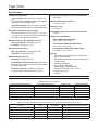
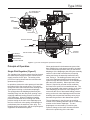
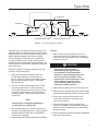
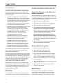
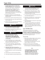
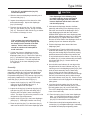
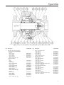
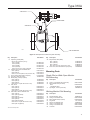
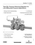
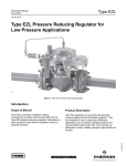
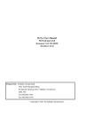
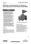
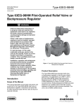
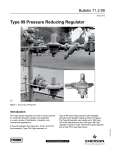
Type 310A
Instruction Manual
Form 5351
March 2010
Type 310A-32A Pressure Reducing Regulator and
Type 310A-32A-32A Working Monitor Regulator
!
Warning
Failure to follow these instructions or
to properly install and maintain this
equipment could result in an explosion
and/or fire causing property damage
and personal injury or death.
Fisher® regulators must be installed,
operated, and maintained in accordance
with federal, state, and local codes,
rules and regulations, and Emerson
Process Management Regulator
Technologies, Inc. instructions.
If the regulator vents gas or a leak
develops in the system, service to
the unit may be required. Failure
to correct trouble could result in a
hazardous condition.
Call a gas service person to service
the unit. Only a qualified person must
install or service the regulator.
W6278
Figure 1. Type 310A Regulator with Type 32A Pilot
Introduction
Scope of the Manual
This Instruction Manual provides installation,
maintenance, and parts ordering information for the
Type 310A-32A pilot-operated, pressure reducing
regulator and the Type 310A-32A-32A working monitor
regulator. Information on equipment used with this
regulator is found in separate manuals.
The Type 310A-32A-32A working monitor regulator
includes Type 310A regulator which functions as the
first-stage regulator in the working monitor situations
by taking the initial pressure reduction and two
Type 32A pilots which serve as the monitoring and
working pilots.
Specifications
Description
Ratings and specifications for the Type 310A
configurations are listed in the Specifications section
on page 2. Some specifications for a specific regulator
are stamped on a nameplate attached to the pilot
spring case (key 1, Figure 9).
D102068X012
The Type 310A-32A pilot-operated, pressure reducing
regulator includes a single Type 32A pilot mounted
on the Type 310A main valve for pressure reducing or
wide-open monitoring applications.
www.fisherregulators.com
Type 310A
Specifications
Available Configurations
Type 310A-32A: Type 310A main valve with one Type 32A pilot for standard pressure reducing and wide-open monitoring applications
Type 310A-32A-32A: Type 310A main valve with two Type 32A pilots for working monitor applications
Body Sizes and End Connection Styles
NPS 1 body with NPT ends; and NPS 1, 2, 3, 4, or 4 x 6 (DN 25, 50, 80, 100, and 100 x 150) body with
CL300 RF or CL600 RF flanged ends
Maximum Inlet and Pilot Supply Pressures(1)
NPT and CL600 RF: 1500 psig (103 bar)
CL300 RF: 750 psig (51,7 bar)
Outlet Pressure Ranges and Proportional Bands
See Table 1
Minimum Differential Pressure(1)
15 psig (1,0 bar)
Maximum Travel
See Table 3
External Pilot Supply and Pilot Vent Connections
1/4 NPT
Temperature Capabilities(1)
Nitrile (NBR) with Wiper Ring:
-20° to 150°F (-29° to 66°C)
Fluorocarbon (FKM) with Wiper Ring:
0° to 150°F (-18° to 66°C)
Fluorocarbon (FKM) without Wiper Ring:
0° to 300°F (-18° to 149°C)
Maximum Pressure Drop(1)
NPT and CL600 RF: 1425 psig (98,3 bar)
CL300 RF: 720 psig (49,6 bar)
Maximum Outlet Pressure(1)
Operating: 700 psig (48,3 bar)
To Avoid Internal Part Damage: 800 psig (55,2 bar)
Exceeding this pressure may result in gas venting from pilot spring case.
Emergency (Casing): 1500 psig (103 bar) or maximum inlet pressure whichever is lower.
Options
• Main valve body without pilot for on-off service
• Remote-mounted pilot
• Electrically controlled pilot using Type 662 Kixcel™
• Travel indicator
• Pressure loaded pilot
• Type 252 pilot supply filter
• Backpressure protection system
• Restricted Trim (30%, 50%, or 70%)
• NACE construction
• Inlet tap
1. The pressure/temperature limits in this Instruction Manual or any applicable standard limitation should not be exceeded.
Table 1. Outlet Pressure Ranges
outlet pressure range, psig (bar)
spring Color
spring part number
10 to 20
(0,69 to 1,4)
Proportional Band, psig (bar)
0.5
(0,03)
Silver
1D809627022
10 to 100
(0,69 to 6,9)
2
(0,14)
Yellow
1E392527022
100 to 250
(6,9 to 17,2)
5
(0,34)
Blue
1D387227022
250 to 600
(17,2 to 41,4)
12
(0,83)
Red
1D465127142
400 to 700
(27,6 to 48,3)(1)
20
(1,4)
Green
13A5543X012
1. Available with Nitrile (NBR) pilot diaphragm only.
Table 2. Recommended Minimum Differential Between Monitoring Pilot Setting and Distribution Pressure
outlet pressure range,
psig (bar)
2
spring
Color
spring
part number
Minimum Pressure at which
monitoring pilot can be set, psig (bar)
10 to 20
(0,69 to 1,4)
Silver
1D809627022
3.0 (0,21) over normal distribution pressure
10 to 100
(0,69 to 6,9)
Yellow
1E392527022
5.0 (0,34) over normal distribution pressure
100 to 250
(6,9 to 17,2)
Blue
1D387227022
10 (0,69) over normal distribution pressure
250 to 600
(17,2 to 41,4)
Red
1D465127142
15 (1,0) over normal distribution pressure
400 to 700
(27,6 to 48,3)
Green
13A5543X012
20 (1,4) over normal distribution pressure
Type 310A
PILOT DIAPHRAGM PLATE
AND YOKE ASSEMBLY
PILOT Control
spring
BLEED VALVE
FIXED
RESTRICTION
BOTTOM
DIAPHRAGM
RELAY SEAT
TOP DIAPHRAGM
MAIN VALVE DIAPHRAGM
THROTTLING SLEEVE
A6571
STATIONARY
VALVE PLUG
MAIN VALVE SPRING
INLET PRESSURE
OUTLET PRESSURE
atmospheric pressure
LOADING PRESSURE
PILOT SUPPLY PRESSURE
Figure 2. Type 310A-32A Regulator Operational Schematic
Principle of Operation
Single-Pilot Regulator (Figure 2)
The regulator inlet pressure enters the pilot through
the external pilot supply line and is utilized as the
supply pressure for the pilot. The setting of the
pilot control spring determines the reduced outlet
(downstream) pressure.
In operation, assume the outlet pressure is less than
the setting of the pilot control spring. Pilot control
spring force then overcomes the force resulting from
outlet pressure acting on the bottom diaphragm.
The spring pushes the diaphragm plate and yoke
assembly away from the relay seat, opening it and
supplying additional loading pressure to the main
valve diaphragm. When this additional loading
pressure exceeds the force resulting from outlet
pressure acting on the main valve diaphragm plus
the force of the main valve spring, the diaphragm is
pushed away from the stationary valve plug. The
throttling sleeve opens wider, and the required gas is
supplied to the downstream system.
When gas demand in the downstream system has
been satisfied, the outlet pressure tends to increase.
The increased outlet pressure acting on the bottom
diaphragm of the diaphragm plate and yoke assembly
results in a force that overcomes the pilot spring
setting and forces the assembly toward the relay
seat, closing it. The loading pressure acting on the
main valve diaphragm bleeds to the downstream
system through the fixed restriction in the diaphragm
plate and yoke assembly. When rapid main valve
closure is required by unusual control conditions,
the bleed valve opens for increased bleed rate. The
force of increased outlet pressure acting on the main
valve diaphragm plus the main valve spring force
overcomes the force of decreased loading pressure
acting on the main valve diaphragm and moves the
throttling sleeve toward the stationary valve plug to
decrease the gas flow to the downstream system.
The top diaphragm in the pilot acts as a sealing
member for the loading chamber and as a balancing
member to the bottom diaphragm. The two
diaphragms are connected by a machine yoke.
Pressure change to the center chamber has little
effect on the positioning of the valve disk.
3
Type 310A
WORKING PILOT
PLUG
RESTRICTION
SPACER
E0385
PLUG
INLET PRESSURE
MONITORING PILOT
OUTLET PRESSURE
ATMOSPHERIC PRESSURE
LOADING PRESSURE
INTERMEDIATE PRESSURE
PILOT SUPPLY PRESSURE
Figure 3. Type 310A-32A-32A Working Monitor Regulator Operational Schematic
Monitor Systems
Wide-Open Monitors (Figure 4)
Monitoring regulators serve as overpressure protection
devices to limit system pressure in the event of failure
of working regulators feeding the system. The control
line of a wide-open monitoring regulator may be
connected downstream of the working regulator, so
that during normal operation the wide-open monitoring
regulator is standing wide-open with the pressure
reduction being taken across the working regulator.
Only in case of working regulator failure does the
wide-open monitoring regulator function.
4
Working Monitors (Figure 5)
The Type 310A-32A-32A differs from wide-open
monitors in that it has working monitor capability. This
means that it normally reduces pressure and throttles
while the second-stage regulator is in operation.
Should the second-stage working regulator fail open,
the Type 310A-32A-32A will take over the entire
pressure reduction function.
The working monitor pilots are adaptations of two
Type 32A pilots with special internal parts, due to the
pressure conditions in this piloting system. A spacer
blocks open the differential regulator portion of the
Type 32A monitoring pilot. A plug in both the working
and monitoring pilots makes the internal bleed non-
Type 310A
E0695
E0694
Figure 4. Wide-Open Monitor System
Figure 5. Working Monitor System
Table 3. Maximum Travel
BODY SIZE, NPS
MAXIMUM TRAVEL, INCH (mm)
1 (25)
0.5
(13)
2 (50)
0.875
(22)
3 (80)
1
(25)
4 (100)
1.125
(29)
1.5
(38)
4 x 6 (100 x 150)
functional. A restriction placed in the external tubing
between the diaphragm loading pressure and the
intermediate pressure acts as a downstream bleed.
If the second-stage working regulator fails open,
the distribution pressure increases to the setting of
the Type 32A monitoring pilot (slightly higher than
the original distribution pressure) and is controlled
at that level by the Type 310A-32A-32A. Thus,
downstream equipment is protected against a major
overpressure condition without disrupting service or
venting gas to atmosphere.
In the working pilot, the inlet pressure is reduced
to a pre-determined pilot supply pressure, which is
further reduced to loading pressure for the Type 310A
diaphragm. The loading pressure is piped through
the portion of the monitoring pilot blocked open by the
spacer and, as long as distribution pressure is below
the setting of the monitoring pilot, passes through the
relay orifice of the monitoring pilot to the diaphragm
case of the Type 310A body.
Distribution pressure is piped back to the monitoring
pilot. As long as the distribution pressure is less
than the monitoring pilot setting, the working pilot
controls the Type 310A to maintain intermediate
pressure. If the distribution pressure increases to
the monitoring pilot setting, the monitoring pilot relay
orifice starts to throttle the loading pressure to the
Type 310A diaphragm. This allows the Type 310A
main spring to move the throttling sleeve closer
to the seat and control distribution pressure at the
monitoring pilot setpoint. Therefore, failure of the
second-stage working regulator is controlled with
only a slight increase in distribution pressure, with
the Type 310A-32A-32A accomplishing the entire
pressure reduction function.
Installation and Startup
!
Warning
Personal injury or equipment damage,
due to bursting of pressure-containing
parts may result if this regulator is
overpressured or is installed where
service conditions could exceed the
limits given in the Specifications section
and on the appropriate nameplate,
or where conditions exceed any
rating of the adjacent piping or piping
connections. To avoid such injury or
damage, provide pressure-relieving or
pressure-limiting devices to prevent
service conditions from exceeding those
limits. Also, check that the installation is
in compliance with all applicable codes
and regulations.
Additionally, physical damage to the
regulator could break the pilot off the
main valve, causing personal injury
and property damage due to bursting
of pressure-containing parts. To avoid
such injury and damage, install the
regulator in a safe location.
Note
For the installation of the regulator in the
line, please consider that SLIP-ON flange
gaskets need to be used on the inlet of
all Type 310A regulators, from NPS 1 to 6
(DN 25 to 150). The gaskets for the outlet
of the Type 310A are standard CL600 RF
welding-neck flange gaskets.
5
Type 310A
LOADING TUBING
HAND VALVE a
1/4 NPT PILOT
SUPPLY CONNECTION
VENT VALVE c
LOCATE 6 TO 10 PIPE
DIAMETERS FROM
VALVE OUTLET
VENT VALVE e
HAND VALVE b
BLOCK VALVE
BLOCK VALVE
ALTERNATE
DOWNSTREAM
CONTROL LINE TAP
1/2-INCH (13 mm)
DOWNSTREAM CONTROL LINE
BYPASS VALVE
VENT VALVE d
BYPASS LINE
24B4134
B2444
Figure 6. Typical Pressure Reducing Installation
Single-Pilot Regulator
Installation
A Type 310A-32A regulator bleeds no gas to
atmosphere during normal operation, thus making
the regulator suitable for installation in pits and
other enclosed locations without elaborate venting
systems. This regulator also can be installed in pits
subject to flooding by venting the pilot spring case
above the expected flood level so that the pilot setting
can be referenced to atmospheric pressure.
1. Use qualified personnel when installing, maintaining, or operating this regulator. Inspect the regulator and the pipeline to be certain both are free of foreign materials.
2. Install the regulator so that the flow arrow cast on the main valve matches the flow direction of process fluid through the regulator.
3. Apply pipe compound to the male pipeline threads before installing a regulator with NPT end connections. Use gaskets between pipeline and regulator flanges when installing a regulator with flanged end connections.
!
Warning
A regulator may vent some gas to
the atmosphere. In hazardous or
6
flammable gas service, vented gas
may accumulate, causing personal
injury, death, or property damage
due to bursting of pressure-retaining
parts. Vent a regulator in hazardous
gas service to a remote, safe location
away from air intakes or any hazardous
location. The vent line or stack opening
must be protected against condensation
or clogging.
4. A Type 32A pilot has a 1/4 NPT vent connection in the spring case. To remotely vent gas from the spring case, remove the screened vent, and connect 1/4-inch (6,4 mm) piping or tubing to the spring case connection.
The piping or tubing should vent to a safe location, have as few elbows as possible,
and have a screened vent on its exhaust. Install the regulator and any remote vent piping or tubing so that the vent is protected from condensation, freezing, or any substance that could clog it.
5. Connect a pilot supply line from the upstream piping to the 1/4 NPT pilot inlet.
6. Connect a downstream control line to a straight run of pipe 6 to 10 pipe diameters from the regulator outlet as shown in Figure 6. If such a distance is not practical, connect the control line away from elbows, swages, nipples, or any area where abnormal flow velocities occur.
Type 310A
7. Install a hand valve in the control line.
8. Install the other end of the downstream control line to the 1/2 NPT connection in either side of the case body (key 1, Figure 10 or 11).
9. Consult the appropriate Instruction Manual for installation of an optional pneumatic or electric remote control-drive unit. For optional remote pneumatic loading of a Type 32A pilot, make the spring case piping connections just as they would be made for remote venting.
Prestartup Considerations
Each regulator is factory-set for the outlet pressure
specified on the order. If no setting was specified,
outlet pressure was factory-set at the mid-range of
the pilot control spring. Before beginning the startup
procedure in this section, make sure the following
conditions are in effect:
• Block valves isolate the regulator
• Vent valves are closed
• A bypass, if any, is in operation
In all cases, check the control spring setting to make
sure it is correct for the application.
caution
Pilot supply pressure must be
introduced into the regulator before
introduction of any downstream
pressure, or internal damage may occur
due to reverse pressurization of the pilot
and main valve components.
Pressure gauges should always be used
to monitor downstream pressure during
startup. Procedures used in putting this
regulator into operation must be planned
accordingly if the downstream system is
pressurized by another regulator or by a
manual bypass.
Note
Pilot supply pressure must be at least
15 psig (1,0 bar) greater than control
pressure to operate the regulator at
rated travel.
Although remote loading or control constructions
may require separate adjustments on associated
equipment, the only adjustment normally necessary
on a Type 310A-32A regulator is the pressure setting
of the pilot control spring. Turning the adjusting
screw clockwise into the spring case increases the
spring compression and pressure setting. Turning
the adjusting screw counterclockwise decreases the
spring compression and pressure setting.
Pilot Adjustment
To adjust a standard Type 32A pilot, loosen the locknut
(key 4, Figure 9), and turn the adjusting screw (key 3,
Figure 9). Then tighten the locknut to maintain the
adjustment position.
Startup
1. Open the upstream block (isolating) valve. Open hand valve A in the external pilot supply line
before opening the downstream isolating valve
(See Figure 6).
2. Open the downstream block (isolating) valve for minimum flow.
3. Slowly open hand valve B in the downstream control line, while at the same time adjusting the pilot setting, if necessary.
4. Completely open the downstream block valve.
5. Slowly close the bypass valve, if any.
Wide-Open Monitor Regulator
Installation
1. For both the wide-open monitoring regulator and the working regulator, perform the Single-Pilot Regulator Installation procedures through step 9.
2. Connect the control line of a wide-open monitoring
regulator (Figure 7) to downstream piping near
the working regulator control line connection.
During normal operation the wide-open monitoring
regulator stands wide-open with the pressure
reduction being taken across the working
regulator. Only in case of working regulator failure
does the wide-open monitoring regulator take
control at its slightly higher setting.
Prestartup Considerations
Each regulator is factory-set for the outlet pressure
specified on the order. If no setting was specified,
7
Type 310A
24B4134
B2445_2
flexible wide-open monitor arrangement that permits
wide-open monitor to be either upstream or
downstream of the working regulator
minimum piping wide-open monitor arrangement that
requires wide-open monitor always to be
Upstream of working regulator
Figure 7. Typical Wide-Open Monitor Installation
outlet pressure was factory-set at the mid-range of the
pilot control spring. Before beginning the startup
procedures in this section, make sure the following
conditions are in effect:
• Block valves isolate the regulator
of the pilot control spring. Turning the adjusting
screw clockwise into the spring case increases the
spring compression and pressure setting. Turning
the adjusting screw counterclockwise decreases the
spring compression and pressure setting.
• Vent valves are closed
Pilot Adjustment
• Hand valves are closed
To adjust a standard Type 32A pilot, loosen the locknut
(key 4, Figure 9), and turn the adjusting screw (key 3,
Figure 9). Then tighten the locknut to maintain the
adjustment position.
• A bypass, if any, is in operation
In all cases, check the control spring setting to make
sure it is correct for the application.
caution
Introduce pilot supply pressure into
the regulator before introducing any
downstream pressure, or internal
damage may occur due to reverse
pressurization of the pilot and main
valve components.
Always use pressure gauges to monitor
downstream pressure during startup.
If the downstream is pressurized
by another regulator, plan startup
procedures accordingly.
Note
Pilot supply pressure must exceed
control pressure by at least
15 psig (1,0 bar) in order to operate
the regulator at rated travel.
Although remote loading or control constructions
may require separate adjustments on associated
equipment, the only adjustment normally necessary
on a Type 310A-32A regulator is the pressure setting
8
Startup
This procedure is to be repeated in turn for each
regulator in the installation.
1. Slowly open the hand valve in the pilot supply line.
2. Slowly open the upstream block (isolating) valve and partially open the downstream block valve for minimum flow.
3. Slowly open the hand valve in the control line while, at the same time, adjusting the pilot setting if necessary.
4. Completely open the downstream block valve.
5. Slowly close the bypass valve, if any.
Working Monitor Regulator
Installation
All Type 310A-32A-32A working monitor regulators
are bench set at the factory according to the service
conditions specified on the customer’s order. Examine
the unit on arrival to make sure no damage has occurred
in shipment. Clean and blow out pipelines to be sure no
welding slag or other foreign material is present.
Type 310A
Hand valve B
Working Pilot
Hand valve A
monitoring
pilot
intermediate pressure
A0714_2
distribution pressure
Figure 8. Typical Working Monitor Installation
Install the Type 310A-32A-32A into the pipeline using
adequate gaskets for flanged regulator units and good
piping technique. Be sure to provide suitable pressure
gauges where appropriate, block valves, bypass
valves and piping, and bleed valves to permit safe
and easy maintenance of both the working monitor
regulator and the second-stage working regulator. Be
sure flow will be in the direction indicated by the arrow
cast on the body.
Refer to the Figure 8 schematic and Figure 14, and
proceed in the following steps.
1. Attach the intermediate pressure control line (1/2 NPT pipe) between the 1/2 NPT pipe tee
(key 72, Figure 14) and the intermediate pressure portion of the downstream piping. Install hand valve B in this line.
2. Connect 1/2 NPT distribution pressure control line piping between the 1/2 NPT connection in the mounting bracket (key 45, Figure 14) and the pipeline downstream of the second-stage working regulator. Include hand valve A in this control line.
Note
Each pilot has a nameplate identifying it
as the working or monitor pilot.
3. Pipe the pilot supply line to 1/4 NPT connection in the back of the working pilot body. Supply pressure should be filtered if excess dirt or condensate is present in the supply gas.
Startup
1. Before introducing any pressure to the unit, close hand valve A in the distribution pressure control line and hand valve B in the intermediate pressure control line.
caution
Pilot supply pressure must be
introduced into the regulator prior
to introduction of any downstream
pressure or internal damage may occur
due to reverse pressurization of the
pilot and main valve components. Pilot
supply pressure must be at least
15 psi (1,0 bar) greater than control
pressure for proper operation.
2. Slowly open the hand valve in the pilot supply line.
3. Slowly open the upstream block valve and partially open the downstream block valve for minimum flow.
4. Slowly open hand valve B and allow the intermediate pressure to increase to the
working pilot setting.
5. Put the second-stage working regulator into operation according to recommended procedures and instructions furnished with the second-stage working regulator.
6. After the distribution pressure has been established
slowly open hand valve A.
4. Install downstream working regulator per guidelines.
9
Type 310A
Pilot Adjustment
The second-stage working regulator must be set to
operate at a lower pressure than the monitoring pilot
or the monitoring pilot will try to take control of the
distribution pressure. Follow the steps listed to obtain
the desired results.
1. Increase the setting of the monitoring pilot by loosening the locknut (key 4, Figure 9) and turning the adjusting screw (key 3, Figure 9) clockwise (into the spring case cap, key 2, Figure 9) until the working pilot is in control of the intermediate pressure and the second-stage working regulator is in control of the distribution pressure.
2. Adjust the setting of the working pilot by loosening the jam nut and turning the adjusting screw clockwise (into the spring case cap) to increase
the intermediate pressure, or counterclockwise (out of the spring case cap) to reduce the intermediate pressure. Adjust until desired intermediate pressure is reached.
3. Adjust the second-stage working regulator to the desired distribution pressure by following instructions for that particular regulator.
4. Adjust the setting of the monitoring pilot to establish the desired emergency distribution
pressure, which is to be maintained in the event of failure of the second-stage working regulator. The steps followed may vary with each piping situation. The basic method remains the same.
The following procedure serves as an example which
can be used or modified to make monitoring pilot
adjustments in any installation.
Increase the outlet pressure setting of the second-stage
working regulator until the monitoring pilot takes control
of the distribution pressure. Adjust the monitoring pilot
setting until the desired emergency distribution pressure
is achieved. Refer to Table 2 for the recommended
minimum differential between the monitoring pilot
setting and the desired distribution pressure.
With settings as desired on both the monitoring and
the working pilots, tighten the locknuts (key 4, Figure 9)
to maintain proper adjustment screw positions. Then
re-adjust the second-stage working regulator to the
desired distribution pressure.
Shutdown
In any installation it is important to slowly open and
close the valves and to vent the outlet pressure before
10
venting the inlet pressure to prevent damage caused
by reverse pressurization of the pilot or main valve.
Single-Pilot Regulators and Wide-Open
Monitor Regulators
As well as applying to a single-pilot regulator (Figure 6),
the steps in this procedure also are valid for a wide-open
monitoring installation (Figure 7) and should be repeated
for each regulator in such an installation.
1. Close the upstream isolating valve.
2. Close block valve A (Figure 6) in the supply line.
3. Close the downstream isolating valve.
4. If the downstream control line taps into the pipeline above the downstream isolating valve, open vent valve C between the regulator and the downstream isolating valve. Permit all pressure to bleed out of the regulator.
If the downstream control line taps into the pipeline below the downstream isolating valve, close hand valve B. Then open vent valve C and vent valve D, permitting all pressure to bleed out of the regulator.
5. Open vent valve E to release any inlet pressure that may be trapped in the regulator.
Working Monitor Regulators
1. Close the upstream isolating valve.
2. Close hand valve in pilot supply line.
3. Close the downstream isolating valve.
4. Open a bleed valve between the second-stage working regulator and the downstream isolating valve. Permit all pressure to bleed out of the working monitor regulator and the second-stage working regulator.
5. Open vent valve to vent any intermediate pressure trapped in the system.
6. Open vent valve to release any inlet pressure trapped in the regulator.
Maintenance
The regulator parts are subject to normal wear
and must be inspected periodically and replaced
as necessary. The frequency of inspection and
replacement depends on the severity of service
Type 310A
conditions and on applicable federal, state and local
codes and regulations.
!
Warning
To avoid personal injury or property
damage from sudden release of pressure,
isolate the regulator from the pressure
system, and release all pressure from the
pilot and main valve before performing
maintenance operations.
Type 32A Pilots
This procedure describes how the pilot can be
completely disassembled and assembled. When
inspection or repairs are required, disassemble only
those parts necessary to accomplish the job. Refer to
Figures 9 and 14 for key numbers.
Disassembly
The pilot may remain on the main valve for steps 1
through 7; however, it must be removed for steps 8
through 15.
10. To inspect or replace the control spring (key 37), unscrew spring case cap (key 2) and remove the control spring and spring seats (key 5).
11. Unscrew the cap screws (key 6), and remove the spring case (key 1).
12. As one unit, remove the diaphragm spacer (key 11), yoke (key 16), orifice assembly (key 12), adaptor (key 17), and valve disk assembly (key 18).
13. Slide out the relay seat assembly (key 12), and inspect the O-rings (key 14). Discard the O-rings if worn or damaged. Also, inspect the seating surface for nicks and scratches, and replace
if necessary.
14. Push the yoke (key 16) and attached parts (keys 9, 8, 15, 10, 18, 17, 19, 20, 35, and 21) through the diaphragm spacer (key 11).
15. Unscrew the adaptor (key 17) from the yoke (key 16). Unscrew the bleed valve (key 20).
1. Remove the piston seat assembly (key 28) from the piston guide (key 23).
On Single-Pilot Regulators and Wide-Open Monitor
Regulators, remove the bleed valve seat (key 19), the
spring (key 35), and the valve disk (key 18). Check
that the holes drilled in the side of the bleed valve seat
and the adaptor are both clean and unplugged.
2. Remove the piston guide (key 23) from the pilot body (key 22).
On Working Monitor Regulators, make sure the plug
(key 52, Figure 14) is firmly in place.
3. Check the O-rings (keys 25 and 26), and replace if worn or damaged.
16. Unscrew the cap nut and nut (keys 10 and 21),
remove the diaphragm plates (key 8) and washers
(key 15), and inspect the diaphragms (key 9).
4. Check the Nylon (PA) disk in the piston seat
assembly, and replace this assembly if worn
or damaged.
5. Remove the retaining ring (key 27), and lift out the piston and spring (keys 29 and 36). On working monitor regulators, remove the working pilot spring (key 36) or the monitoring pilot spacer (key 53, Figure 14).
Note
The edges of the diaphragms can be
expected to curl up. They will flatten out
within a few minutes depending on the
temperature. Warming them will help,
but do not exceed 150°F (66°C).
6. Inspect the valve seating surface on the small end of the piston for nicks and scratches.
Assembly
7. Use a wire with a hooked end to remove the piston
guide bushing O-ring (key 34). Check the O-rings
(keys 30 and 34), and replace if worn or damaged.
It is recommended that new diaphragms and O-rings
be installed during assembly. If these parts are to be
reused, be sure that they are carefully inspected and
that no damage has occurred. Lubricate all O-rings.
8. Disconnect the loading tubing and the external supply line from the pilot (Figure 2); and remove the pilot from the main valve.
9. Release control spring compression by loosening the locknut (key 4) and backing out the adjusting screw (key 3).
1. Place the O-ring (key 34) in the piston guide (key 23).
2. Install the O-rings (keys 25 and 26) on the piston guide.
3. Install the O-ring (key 30) on the piston (key 29).
11
Type 310A
4. On single-pilot regulators and wide-open monitor regulators, place the spring (key 36) in the piston guide (key 23). Install the piston, and secure with the retaining ring (key 27).
On working monitor regulators, place the spring (key 36 - working pilot) or spacer
(key 53 - monitoring pilot) in the piston guide. Install the piston and secure it in the piston guide with the retaining ring (key 27).
5. Install the O-ring (key 13) on the piston seat assembly (key 28), and screw the assembly into the piston guide.
6. Install the piston guide in the pilot body (key 22).
7. Insert the bleed valve (key 20) through the bleed valve seat (key 19).
8. Install the spring (key 35) and valve disk assembly (key 18) onto the bleed valve (key 20).
caution
Be sure the bleed valve seat is centered
in the yoke while installing the adaptor.
9. Place the above assembly in the yoke (key 16), and screw on the adaptor (key 17).
caution
Each diaphragm (key 9) has one
side coated with rubber. Install the
diaphragms so that the rubber sides
face each other. If the diaphragms are
installed any other way, the pilot will not
work properly.
10. Place the diaphragm (key 9), diaphragm plate (key 8), and sealing washer (key 15) on the yoke, and secure with the cap screw (key 10).
11. Place the other diaphragm, diaphragm plate, and sealing washer on the adaptor, and secure with the nut (key 21).
12. Insert this entire assembly through the diaphragm spacer (key 11) until the outer edges of both diaphragms are in place on the spacer.
13. Fit the O-rings (key 14) on the orifice assembly
(key 12).
14. Rotate the yoke to receive the orifice assembly.
15. Place entire assembly on the pilot body (key 22).
12
caution
To avoid crushing the diaphragm, do not
exceed the torque specified in step 16.
16. Apply lubricant to cap screws (key 6). Insert the cap screws in the spring case (key 1) and pilot body, and tighten the cap screws to 25 to 30 foot-pounds (34 to 41 N•m).
17. If removed, install the spring seats (key 5) and the control spring (key 37).
18. Install the cover gasket (key 7), spring case cap (key 2), adjusting screw (key 3), and locknut (key 4).
19. Install the pilot into the main valve using the pipe nipple (not shown).
20. Connect the loading tubing from the male elbow
on the base body (key 2, Figures 10 and 11) to
the connector on the side of the pilot. Refer to
Figure 1 for the assembled location of the tubing,
elbow, and connector.
Type 310A Main Valve
This procedure describes how to completely
disassemble and assemble a main valve. When
inspection or repairs are required, disassemble only
those parts necessary to accomplish the job; then start
the assembly at the appropriate step. Key numbers
are referenced in Figures 10 and 11.
Disassembly
1. Disconnect the loading tubing from the connection in the base body (key 2). Disconnect the downstream pressure control line from
the connection in the case body (key 1) and the external supply line from the pilot.
2. Remove the main valve from the pipeline.
3. Remove the cap screws (key 14), and separate the case body (key 1) from the base body (key 2).
Note
If a body gasket (key 29) is not present,
one must be installed when a new
diaphragm is installed. Also, if the
soft seat inside the sleeve (key 3) is
damaged, the sleeve (key 3), washer or
O-ring (key 11), disk retainer (key 12),
Type 310A
disk (key 27), and disk holder (key 28)
need to be replaced.
4. Slide the sleeve and diaphragm assembly out of the case body (key 1).
5. Inspect the seating area of the sleeve for nicks and erosion damage. Inspect the diaphragm
(key 6) for damage.
6. Remove the cap screw (key 10), disk retainer (key 12), disk holder (key 28), O-ring or washer
(key 11). Examine the disk and O-ring or washer for evidence of damage or wear.
Note
If the regulator has restricted capacity
trim, the percentage of full capacity will
be stamped on the outside of the disk
retainer. If this is done, the change
should be noted on the nameplate to
avoid confusion.
7. If either the sleeve or diaphragm must be replaced, remove the screws (key 13) and
diaphragm plate (key 4). Remove the split ring (key 7), and slide the lower diaphragm plate
(key 5) off the sleeve. This also exposes the O-ring (key 9) in the lower diaphragm plate
for inspection.
Assembly
Before assembly, be sure all parts are clean. During
assembly, lubricate all O-rings and both diaphragm
beads with a high quality lubricant. Be certain the
Polytetrafluoroethylene (PTFE) backup rings (key 26)
are properly installed in the O-ring grooves in the
base body (key 2) and the case body (key 1).
1. Inspect the O-rings (key 9), and PTFE backup
rings (key 26) in the base body (key 2). If
damaged, replace with new parts.
2. Inspect the O-ring (key 9), backup rings (key 26), and wiper ring (key 19) in the case body (key 1). Replace with new parts if wear or damage is noted. The wiper ring will not be present in units designed for high temperatures.
3. Inspect the O-ring (key 9) in the lower diaphragm plate (key 5). If damaged, install a new O-ring.
4. Place the split ring (key 7) on the sleeve (key 3), and insert the sleeve in the lower diaphragm plate.
caution
If the diaphragm in the following step
is installed with the wrong side against
the lower diaphragm plate, the beads
become distorted and the main valve will
not shut off properly.
5. Lubricate both diaphragm beads to facilitate assembly and sealing of the diaphragm (key 6). Place the inner bead of the diaphragm on the lower diaphragm plate with the side marked SPRING SIDE against the lower diaphragm plate. Add the upper diaphragm plate (key 4), and install the screws (key 13), tighten them down evenly. Be sure the inner bead of the diaphragm does not partially slip out from between the plates.
6. Fold the diaphragm down around the lower diaphragm plate.
7. Fit the disk (key 27) into the disk holder (key 28). Install the disk retainer (key 12) on top of the disk, being sure the leading edge of the disk is properly positioned around the outside of the retainer and is not pinched under the retainer. Place the O-ring or washer (key 11) on the sub-assembly and install in the base body (key 2). Secure with the cap screw (key 10).
8. On units with travel indicator, fit one edge of the flanged head of the travel indicator rod (key 15) into the groove in the diaphragm plate (key 4) and slide the entire assembly into the base body (key 2), being sure the travel indicator rod is properly oriented so it enters and extends through the hole in the base body and is visible through the travel indicator cover (key 20). Check to make sure indicator rod is still engaged in the diaphragm
plate groove.
9. Lubricate the body gasket (key 29) and the gasket surface of the base body (key 2), place the body gasket (key 29) on the base body. Then fit the diaphragm bead over the machined nose of the base body.
10. Place the spring (key 8) in the lower diaphragm plate. On units with travel indicator, orient the case body so that the pilot mounting bracket
(key 45) is in line with the travel indicator.
11. Fasten the two body halves together with the cap screws (key 14), and tighten hand tight. Lubricating the threads will make proper tightening easier.
13
Type 310A
Table 4. Maximum Cap Screw (key 14) Torque Values
BODY SIZE,
NPS (DN)
MAXIMUM TORQUE VALUE,
FOOT-POUNDS (N•m)
1 (25)
2 (50)
3 (80)
4 and 4 x 6 (100 and 100 x 150)
55
105
125
500
(75)
(142)
(170)
(678)
caution
Overtightening the cap screws in
step 12 can damage the diaphragm. Do
not exceed the torque value listed in
Table 4 when tightening the cap screws.
12. Alternately tighten the cap screws on opposite sides of the unit to evenly compress the gasket. Follow this sequence several times until the cap screws will not turn at the maximum torque given in Table 4. If this procedure is properly followed, the gap between the two body halves will be uniform all the way around.
13. Connect the external supply line to the pilot.
Parts Ordering
Each Type 310A regulator is assigned a serial number,
which can be found on the nameplate. Refer to the
number when contacting your local Sales Office for
technical information or when ordering parts.
When ordering replacement parts, reference the key
number of each needed part as found in the following
parts list. Separate kit containing all recommended
spare parts is available.
Parts List
Type 32A Pilot (Figure 9)
Key Description Repair Kits (Include keys 7, 9, 13, 14, 15, 18, 25,
26, 28, 30, and 34)
With Fluorocarbon (FKM) disk, Nitrile (NBR)
diaphragm, disk and O-rings
With Fluorocarbon (FKM) disk, diaphragm,
and O-rings
1
Spring Case, Steel
2
Spring Case Cap, Zinc-plated steel
3 Adjusting Screw,
Standard mounting, Zinc-plated steel
Type 662 Kixcel mounting, Steel
4 Locknut, Zinc-plated steel 5 Spring Seat, Steel (2 required) 6 Cap Screw, Zinc-plated steel (4 required) 7* Gasket, Composition 8 Diaphragm Plate, Zinc-plated steel (2 required) *Recommended Spare Part
14
Part Number
R32AX000012
R32AX000022
2R742222012
11A8122X012
1D995448702
18B3500X062
1H483324122
1R742524092
1B139324052
1R742604022
1R742724152
Key Description 9* Diaphragm (2 required)
Nitrile (NBR) Fluorocarbon (FKM)
10 Cap Nut, Stainless steel 11 Diaphragm Spacer
Steel (standard)
Steel (NACE)
12 Orifice Assembly
416 Stainless steel (standard)
316 Stainless steel (NACE)
13* O-ring
Nitrile (NBR) (standard) Fluorocarbon (FKM)
14* O-ring (2 required)
Nitrile (NBR) (standard) Fluorocarbon (FKM)
15* Washer, Plated steel with
bonded synthetic rubber (2 required) 16 Yoke
410/416 Stainless steel (standard)
316 Stainless steel (NACE)
17 Adaptor
410/416 Stainless steel (standard)
316 Stainless steel (NACE)
18* Valve Disk Assembly
416 Stainless steel/Fluorocarbon (FKM)
Stainless steel with PTFE disk 316 Stainless steel/Fluorocarbon (FKM) (NACE)
19 Bleed Orifice, 316 Stainless steel 20 Bleed Valve
416 Stainless steel (standard)
316 Stainless steel (NACE)
21 Nut, Zinc-plated steel 22 Pilot Body, Steel 23 Piston Guide
410/416 Stainless steel (standard)
316 Stainless steel (NACE)
25* O-Ring
Nitrile (NBR) (standard) Fluorocarbon (FKM)
26* O-Ring
Nitrile (NBR) (standard) Fluorocarbon (FKM)
27 Retaining Ring, Carbon-plated steel 28* Piston Seat Assembly
416 Stainless steel/Nylon (PA) (standard)
316 Stainless steel/Nylon (PA) (NACE)
29 Piston
416 Stainless steel (standard) 316 Stainless steel (NACE)
30* O-Ring
Nitrile (NBR) (standard) Fluorocarbon (FKM)/PTFE
33 Bushing
303 Stainless steel (standard) 316 Stainless steel (NACE)
34* O-Ring
Nitrile (NBR) (standard) Fluorocarbon (FKM)/PTFE
35 Spring
302 Stainless steel (standard)
Nickel-Based alloy (NACE)
36 Spring
302 Stainless steel Nickel-Based alloy (NACE)
37 Control Spring, Zinc-plated steel
10 to 20 psig (0,69 to 1,4 bar), Silver
10 to 100 psig (0,69 to 6,9 bar), Yellow 100 to 250 psig (6,9 to 17,2 bar), Blue 250 to 600 psig (17,2 to 41,4 bar), Red 400 to 700 psig (27,6 to 48,3 bar), Green
Part Number
1R742806992
1U448302462
1D651538992
2R742924092
2R7429X0052
1R7430000A2
1R7430X0022
1D687506992
1N430406382
1E216306992
1L949306382
1J186999012
1R743335132
1R7433X0012
1R743435132
1R7434X0012
10A4912X012
12A3962X012
10A4912X082
1R743835162
1D986735132
1D9867X0012
1A309324122
34B3863X012
34B3880X012
34B3880X022
1U379006992
1V101506382
1F463606992
1N571406382
1R744228982
14B3881X012
14B3881X022
1R744535232
1R7445X0012
1E218106992
1N530106382
1F262035032
1F2620X0012
1D191706992
1N423906382
1R744637022
12B7884X012
1U550637022
12B7883X012
1D809627022
1E392527022
1D387227022
1D465127142
13A5543X012
Type 310A
3
4
2
5
7
37
39
1
5
12
15
27
10
8
6
26
9
11
16
22
14
33
35
25
9
28
20
70
18
17
19
15
14
30
36
34
29
13
23
21
8
34B4129-B
Figure 9. Type 32A Pilot Assembly
Key Description
38 Connector, Carbon-plated steel (not shown) 39 Type Y602-1 Vent Assembly, for pilot mounted on
main valve (not required when pressure loaded) 41 Drive Screw, 18-8 Stainless steel (4 required)
52 Plug, Brass
53 Spacer, 304 Stainless steel
66 Sealing Washer, (For use with pressure
loaded pilot only) 70 Pipe Bushing, Carbon-plated steel
71 Pipe Nipple, Zinc Part Number
15A6002X462
17A6570X012
1A368228982
1V211714012
17B8959X012
1V205699012
1B6149X0012
1B828626012
Type 310A Main Valve
Key Description
Repair Kits (Include keys 6, 9, 11, 19,
26, 27, and 29)
With Nitrile (NBR) O-rings
NPS 1 (DN 25)
NPS 2 (DN 50)
NPS 3 (DN 80)
NPS 4 and 4 x 6 (DN 100 and 100 x 150)(1)
Part Number
R310X000012
R310X000032
R310X000052
R310X000072
1. In case the kit R310X000072 is for a size NPS 4 x 6 (DN 100 x 150) Type 310A, it is necessary to purchase an extra Wiper Ring (PN 1R752604152).
15
Type 310A
34B4130-A
Figure 10. NPS 1 (DN 25) Body Size Type 310A Main Valve Assembly
Key Description
Repair Kits (Include keys 6, 9, 11, 19,
26, 27, and 29) (continued)
With Fluorocarbon (FKM) O-rings
NPS 1 (DN 25)
NPS 2 (DN 50)
NPS 3 (DN 80)
NPS 4 and 4 x 6 (DN 100 and 100 x 150)
Part Number
R310X000022
R310X000042
R310X000062
R310X000082
1 Case Body, WCC steel
Without inlet tapping (standard) or with travel indicator
NPT
NPS 1 44B3869X012
CL300 RF
NPS 1 (DN 25)
44B3870X012
NPS 1 (DN 25) (NACE)
44B3870X022
NPS 2 (DN 50)
44B3872X012
NPS 2 (DN 50) (NACE)
44B3872X022
NPS 3 (DN 80)
44B3874X012
NPS 3 (DN 80) (NACE)
44B3874X022
NPS 4 and 4 x 6 (DN 100 and 100 x 150) 44B3876X012
NPS 4 (DN 100) (NACE) 44B3876X022
CL600 RF
NPS 1 (DN 25)
44B3871X012
NPS 2 (DN 50)
44B3873X012
NPS 3 (DN 80)
44B3875X012
NPS 4 (DN 100)
44B3877X012
16
Key Description 1
Case Body, WCC steel (continued)
With inlet tapping
CL300 RF
NPS 1 (DN 25)
NPS 2 (DN 50)
CL600RF
NPS 1 (DN 25)
NPS 2 (DN 50)
2 Base Body, WCC steel
Without travel indicator (standard)
NPT
NPS 1 CL300 RF
NPS 1 (DN 25)
NPS 1 (DN 25) (NACE)
NPS 2 (DN 50)
NPS 2 (DN 50) (NACE)
NPS 3 (DN 80)
NPS 3 (DN 80) (NACE)
NPS 4 (DN 100)
NPS 4 (DN 100) (NACE)
NPS 4 x 6 (DN 100 x 150)
Part Number
24B5843X012
24B6356X012
24B6355X012
24B6357X012
34B4103X012
34B3980X012
34B3980X022
44B3981X012
44B3981X022
44B3982X012
44B3982X022
44B3983X012
44B3983X022
44B4110X012
Type 310A
34B4131-A
Figure 11. NPS 2, 3, and 4 (DN 50, 80, and 100) Body Size Type 310A Main Valve Assembly
Key Description
Part Number
2 Base Body, WCC steel (continued)
Without travel indicator (standard) CL600 RF
NPS 1 (DN 25)
34B4104X012
NPS 2 (DN 50)
44B4105X012
NPS 3 (DN 80)
44B4106X012
NPS 4 (DN 100)
44B4107X012
NPS 4 x 6 (DN 100 x 150)
44B4111X012
With travel indicator
NPT
NPS 1 3R746822012
CL300 RF
NPS 1 (DN 25)
3U357022012
NPS 1 (DN 25) (NACE)
3U3570X0072
NPS 2 (DN 50)
4U356822012
NPS 2 (DN 50) (NACE)
4U3568X0072
NPS 3 (DN 80)
4U357222012
NPS 3 (DN 80) (NACE)
4U3572X0062
NPS 4 (DN 100)
4U357622012
NPS 4 (DN 100) (NACE)
4U3576X0022
NPS 4 x 6 (DN 100 x 150)
41A8162X012
CL600 RF
NPS 1 (DN 25)
3R746622012
NPS 2 (DN 50)
4R740422012
NPS 3 (DN 80)
4R749422012
NPS 4 (DN 100)
4R751222012
NPS 4 x 6 (DN 100 x 150)
40A9616X012
Key Description 3 Sleeve, 304 Stainless steel
NPS 1 (DN 25)
NPS 2 (DN 50)
NPS 3 (DN 80)
NPS 4 (DN 100)
NPS 4 x 6 (DN 100 x 150)
4 Diaphragm Plate, Steel
NPS 1 (DN 25)
NPS 1 (DN 25) (NACE)
NPS 2 (DN 50)
NPS 2 (DN 50) (NACE)
NPS 3 (DN 80)
NPS 3 (DN 80) (NACE)
NPS 4 and 4 x 6 (DN 100 and 100 x 150)
NPS 4 (DN 100) (NACE)
5 Lower Diaphragm Plate, Steel
NPS 1 (DN 25)
NPS 1 (DN 25) (NACE)
NPS 2 (DN 50)
NPS 2 (DN 50) (NACE)
NPS 3 (DN 80)
NPS 3 (DN 80) (NACE)
NPS 4 and 4 x 6 (DN 100 and 100 x 150)
NPS 4 (DN 100) (NACE)
Part Number
10A8220X012
20A8221X012
20A8222X012
20A8223X012
20A9619X012
1R747024092
1R7470X0012
1R740724392
1R7407X0012
1R749624392
1R7496X0012
1R751425012
1R7514X0012
1R747124092
1R7471X0012
1R740922012
1R7409X0012
2R749822012
2R7498X0012
2R751622012
2R7516X0012
17
Type 310A
Key Description 14B6653_A
Figure 12. Travel Indicator Assembly
Key Description 6* Diaphragm
Nitrile (NBR)
NPS 1 (DN 25)
NPS 2 (DN 50)
NPS 3 (DN 80)
NPS 4 and 4 x 6 (DN 100 and 100 x 150)
Fluorocarbon (FKM)
NPS 1 (DN 25)
NPS 2 (DN 50)
NPS 3 (DN 80)
NPS 4 and 4 x 6 (DN 100 and 100 x 150)
7 Split Ring, 410/416 Stainless steel
NPS 1 (DN 25)
NPS 1 (DN 25) (NACE)
NPS 2 (DN 50)
NPS 2 (DN 50) (NACE)
NPS 3 (DN 80)
NPS 3 (DN 80) (NACE)
NPS 4 and 4 x 6 (DN 100 and 100 x 150)
NPS 4 (DN 100) (NACE)
8 Spring, Steel
NPS 1 (DN 25)
NPS 1 (DN 25) (NACE)
NPS 2 (DN 50)
NPS 2 (DN 50) (NACE)
NPS 3 (DN 80)
NPS 3 (DN 80) (NACE)
NPS 4 (DN 100)
NPS 4 (DN 100) (NACE)
NPS 4 x 6 (DN 100 x 150)
9* O-Ring (3 required)
Nitrile (NBR)/PTFE
NPS 1 (DN 25)
NPS 2 (DN 50)
NPS 3 (DN 80)
NPS 4 and 4 x 6 (DN 100 and 100 x 150)
Fluorocarbon (FKM)/PTFE
NPS 1 (DN 25)
NPS 2 (DN 50)
NPS 3 (DN 80)
NPS 4 and 4 x 6 (DN 100 and 100 x 150)
10 Cap Screw, Stainless steel
NPS 1 (DN 25)
NPS 1 (DN 25) (NACE)
NPS 2 (DN 50)
NPS 2 (DN 50) (NACE)
*Recommended Spare Part
18
Part Number
1R747299982
1R741099982
1R749999982
2R751799982
21A1929X022
21A1930X022
21A1931X022
21A1932X022
1R747335132
1R7473X0012
1R741135132
1R7411X0012
1R750035132
1R7500X0012
1R751835132
1R7518X0012
1U888627112
13B7203X012
1U888527132
12B7885X012
1U888727082
13B9520X012
1U888827082
14B3560X012
10A9620X012
1E736906992
1H2921X0012
1K8776X0022
1H862106992
1N163306382
1R752306382
1L111206382
1U448406382
1R747538982
1R7475X0012
1R741438982
1R7414X0012
10 Cap Screw, Stainless steel (continued)
NPS 3 (DN 80)
NPS 3 (DN 80) (NACE)
NPS 4 and 4 x 6 (DN 100 and 100 x 150)
NPS 4 (DN 100) (NACE)
11* Washer, Plated steel/composition
(for NPS 1 (DN 25) body) (not shown) O-Ring
Nitrile (NBR)
NPS 2 (DN 50)
NPS 3 (DN 80)
NPS 4 and 4 x 6 (DN 100 and 100 x 150)
Fluorocarbon (FKM)
NPS 2 (DN 50)
NPS 3 (DN 80)
NPS 4 and 4 x 6 (DN 100 and 100 x 150)
12 Disk Retainer, Stainless steel
NPS 1 (DN 25)
30% Capacity 50% Capacity 70% Capacity
100% Capacity 100% Capacity (NACE)
NPS 2 (DN 50)
30% Capacity 50% Capacity 70% Capacity 100% Capacity 100% Capacity (NACE)
NPS 3 (DN 80)
30% Capacity 50% Capacity
70% Capacity 100% Capacity 100% Capacity (NACE)
NPS 4 and 4 x 6 (DN 100 and 100 x 150)
30% Capacity 50% Capacity 70% Capacity 100% Capacity 100% Capacity (NACE)
13 Screw, Zinc-plated steel (8 required)
NPS 1 and 2 (DN 25 and 50)
NPS 1 and 2 (DN 25 and 50) (NACE)
NPS 3 (DN 80)
NPS 3 (DN 80) (NACE)
NPS 4 and 4 x 6 (DN 100 and 100 x 150)
NPS 4 (DN 100) (NACE) 14 Cap Screw (8 required)
NPS 1 (DN 25)
NPS 2 (DN 50)
NPS 3 (DN 80)
NPS 4 and 4 x 6 (DN 100 and 100 x 150)
15 Travel Indicator Rod, 316 Stainless steel
NPS 1 (DN 25)
NPS 2 (DN 50)
NPS 3 (DN 80)
NPS 4 (DN 100)
NPS 4 x 6 (DN 100 x 150)
16 Bushing, 316 Stainless steel
17 O-ring, Fluorocarbon (FKM)/PTFE
18 Travel Indicator Scale, 18-8 Stainless steel
NPS 1 (DN 25)
NPS 2 (DN 50)
NPS 3 (DN 80)
NPS 4 (DN 100)
NPS 4 x 6 (DN 100 x 150)
Part Number
1R740638982
1R7406X0012
1R741338982
1R7413X0012
1U984499012
1F463606992
10A8217X022
10A8218X032
1N571406382
10A8217X012
10A8218X012
10A8202X012
10A8203X012
19A0690X012
10A8204X012
10A8204X022
20A8205X012
20A8206X012
20A8207X012
20A8208X012
20A8208X022
20A8209X012
20A8210X012
20A8211X012
10A8212X012
10A8212X022
20A8213X012
20A8214X012
20A8215X012
20A8216X012
20A8216X022
1A3321X0032
1A3321X0042
1U154838982
1U1548X0032
1E304428982
1E3044X0012
1N2579X0022
1A771132982
1L469632982
1R752132982
1R7477X0012
1R7416X0012
1R7503X0012
1R7527X0012
10A9621X022
1F2620X0012
1N423906382
1R747838982
1R741738982
1R750838982
1R752238982
10A9622X012
Type 310A
Type 32A Pilot
Loading Tubing
Check Valve
14B6654
Type 310A main valve
Figure 13. Backpressure Protection System Assembly
Key Description 19 Wiper Ring, Nitrile (NBR)
(Not for use over 200°F (93°C))
NPS 1 (DN 25)
NPS 2 (DN 50)
NPS 3 (DN 80)
NPS 4 (DN 100)
NPS 4 x 6 (DN 100 x 150) (2 required)
20 Indicator Cap, 410/416 Stainless steel
NPS 1 (DN 25)
NPS 2 (DN 50)
NPS 3, 4, and 4 x 6 (DN 80, 100, and 100 x 150)
21 Screw, Carbon-plated steel (2 required) 24 Pipe Plug, Steel (not shown) 26* Backup Ring, PTFE (4 required)
NPS 1 (DN 25)
NPS 2 (DN 50)
NPS 3 (DN 80)
NPS 4 and 4 x 6 (DN 100 and 100 x 150)
27* Disk, PTFE NPS 1 (DN 25)
NPS 2 (DN 50)
NPS 3 (DN 80)
NPS 4 and 4 x 6 (DN 100 and 100 x 150)
28 Disk Holder, 303/316 Stainless steel
NPS 1 (DN 25)
NPS 1 (DN 25) (NACE)
NPS 2 (DN 50)
NPS 2 (DN 50) (NACE)
NPS 3 (DN 80)
NPS 3 (DN 80) (NACE)
NPS 4 and 4 x 6 (DN 100 and 100 x 150)
NPS 4 (DN 100) (NACE)
Part Number
1R748204152
1R745203362
1R750704152
1R752604152
1R752604152
Key Description Part Number
29* Body Gasket, Nitrile (NBR)
NPS 1 (DN 25)
NPS 2 (DN 50)
NPS 3 (DN 80)
NPS 4 and 4 x 6 (DN 100 and 100 x 150)
38 Drive Screw, 18-8 Stainless steel (4 required)
11A6853X012
11A6854X012
11A6855X012
11A6856X012
1A368228982
12A6413X012
12A6414X012
12A6415X012
1C941928982
1A369224492
Mounting Parts
1V435606242
1V435706242
1V435806242
1V435906242
Key Description 10A8224X012
10A8225X012
10A8226X012
10A8227X012
10A8228X012
10A8228X022
10A8229X012
10A8229X022
10A8234X012
10A8234X022
10A8235X012
10A8235X022
Single-Pilot or Wide-Open Monitor
Pilot Mounting
22 Tubing, 316 Stainless steel (not shown)
23 Elbow, Plated steel (not shown)
Steel
316 Stainless steel
71 Pipe Nipple, 1/2 NPT (not shown) Part Number
0500213809W
15A6002XW32
15A6002X612
1B828626012
Working Monitor Pilot Mounting
Key Description 45
46
50
52
53
54
55
56
Mounting Bracket, Steel
Tubing, 316 Stainless steel
Elbow, Plated steel (5 required)
Plug, Brass Spacer, 304 Stainless steel
Tubing, 316 Stainless steel
Tubing, 316 Stainless steel
Connector
Part Number
14B8803X012
0500213809W 15A6002XW32
1V211714012
17B8959X012
0500213809W 0500213809W
15A6002XW22
*Recommended Spare Part
19
Type 310A
working pilot
pilot supply
connection
54B4132
Figure 14. Type 310A-32A-32A Assembly
Key Description Part Number
Key Description 60
61
62
1K201428992
1B352626012
1B860628992
64
69
72
Pipe Tee, Carbon steel
Pipe Nipple, Galvanized steel
Pipe Tee, Carbon steel
Part Number
Restriction, 316 Stainless steel
Mounting Bar, 303 Stainless steel
Pipe Tee, Carbon steel
1D7469X00A2
14B5625X012
1H359428992
Industrial Regulators
Natural Gas Technologies
TESCOM
Emerson Process Management
Regulator Technologies, Inc.
Emerson Process Management
Regulator Technologies, Inc.
Emerson Process Management
Tescom Corporation
USA - Headquarters
McKinney, Texas 75069-1872 USA
Tel: 1-800-558-5853
Outside U.S. 1-972-548-3574
USA - Headquarters
McKinney, Texas 75069-1872 USA
Tel: 1-800-558-5853
Outside U.S. 1-972-548-3574
USA - Headquarters
Elk River, Minnesota 55330-2445 USA
Tel: 1-763-241-3238
Asia-Pacific
Shanghai, China 201206
Tel: +86 21 2892 9000
Asia-Pacific
Singapore, Singapore 128461
Tel: +65 6777 8211
Europe
Bologna, Italy 40013
Tel: +39 051 4190611
Europe
Bologna, Italy 40013
Tel: +39 051 4190611
Gallardon, France 28320
Tel: +33 (0)2 37 33 47 00
Middle East and Africa
Dubai, United Arab Emirates
Tel: +971 4811 8100
Europe
Selmsdorf, Germany 23923
Tel: +49 (0) 38823 31 0
For further information visit www.fisherregulators.com
The Emerson logo is a trademark and service mark of Emerson Electric Co. All other marks are the property of their prospective owners. Fisher is a mark owned by Fisher Controls, Inc., a
business of Emerson Process Management.
The contents of this publication are presented for informational purposes only, and while every effort has been made to ensure their accuracy, they are not to be construed as warranties or
guarantees, express or implied, regarding the products or services described herein or their use or applicability. We reserve the right to modify or improve the designs or specifications of such
products at any time without notice.
Emerson Process Management does not assume responsibility for the selection, use or maintenance of any product. Responsibility for proper selection, use and maintenance of any Emerson
Process Management product remains solely with the purchaser.
©Emerson Process Management Regulator Technologies, Inc., 1994, 2010; All Rights Reserved