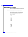
1
EMC Enterprise Storage
Departmental Switch
Model DS-16B2
Fabric OS
Version 3.0
PROCEDURES MANUAL
P/N 069001111-A01
EMC Corporation
Corporate Headquarters: (508) 435-1000, (800) 424-EMC2
171 South Street, Hopkinton, MA 01748-9103
Fax: (508) 435-5374 Service: (800) SVC-4EMC
Copyright © 2001 EMC Corporation. All rights reserved.
Printed September, 2001
EMC believes the information in this publication is accurate as of its publication date. The information is
subject to change without notice.
THE INFORMATION IN THIS PUBLICATION IS PROVIDED “AS IS.” EMC CORPORATION MAKES NO
REPRESENTATIONS OR WARRANTIES OF ANY KIND WITH RESPECT TO THE INFORMATION IN THIS
PUBLICATION, AND SPECIFICALLY DISCLAIMS IMPLIED WARRANTIES OF MERCHANTABILITY OR
FITNESS FOR A PARTICULAR PURPOSE.
Use, copying, and distribution of any EMC software described in this publication requires an applicable
software license.
Regulatory Agency Information
Departmental Switch Model DS-16B2 has been extensively tested and certified to meet UL1950, CSA 22.2
No 950, IEC 60950/EN60950; Safety of Information Technology Equipment including Electrical Business
Equipment, FCC Rules Part 15 Subpart B; CISPR22 Class A; European EMC Directive 89/336/EEC on,
electromagnetic compatibility.
This class A digital apparatus complies with Canadian ICES-003.
Cet appareil numérique de la classe A est conforme à la norme NMB-003 du Canada.
Warning!
This is a Class A product. In a domestic environment this product may cause radio interference in which
case the user may be required to take adequate measures.
Achtung!
Dieses ist ein Gerät der Funkstörgrenzwertklasse A. In Wohnbereichen können bei Betrieb dieses Gerätes
Rundfunkstörungen auftreten, in welchen Fällen der Benutzer für entsprechende Gegenmaßnahmen
verantwortlich ist.
Attention!
Ceci est un produit de Classe A. Days un environment domestic, be produit risque de career des
interferences radioélectriques, il appertained alors à l'utilisateur de prendre les mesures spécifiques
appropriées.
This equipment generates, uses, and may emit radio frequency energy. The equipment has been type tested
and found to comply with the limits for a Class A digital device pursuant to Part 15 of FCC rules, which are
designed to provide reasonable protection against such radio frequency interference.
ii
Departmental Switch DS-16B2 Fabric OS Procedures Manual
Operation of this equipment in a residential area may cause interference in which case the user
at his own expense will be required to take whatever measures may be required to correct the
interference.
Any modifications to this device - unless expressly approved by the manufacturer - can void the User
authority to operate this equipment under part 15 of the FCC rules.
Trademark Information
EMC, EMC2, Symmetrix, and CLARiiON are registered trademarks and where information lives is a trademark of EMC Corporation.
All other trademarks used herein are the property of their respective owners.
Departmental Switch DS-16B2 Fabric OS Procedures Manual
iii
iv
Departmental Switch DS-16B2 Fabric OS Procedures Manual
Contents
Preface .......................................................................................................................... vii
Chapter 1
Setting the Initial Switch Configuration
Logging In to a Switch .................................................................... 1-2
Enabling Licensed Features............................................................ 1-3
Displaying the Installed Feature Licenses.................................... 1-4
Changing the Admin Password and User ID .............................. 1-4
Configuring the IP Address ........................................................... 1-5
Displaying the Fabric-Wide Device Count................................... 1-6
Chapter 2
Basic Switch Configuration Procedures
Setting the Telnet Timeout Value ................................................... 2-2
Displaying the Firmware Version.................................................. 2-2
Setting the Switch Date and Time.................................................. 2-3
Displaying the System Configuration Settings ........................... 2-4
Backing Up the System Configuration Settings .......................... 2-4
Restoring the System Configuration Settings.............................. 2-5
Upgrading or Restoring the Switch Firmware ............................ 2-6
Disabling a Switch ........................................................................... 2-6
Enabling a Switch ............................................................................ 2-7
Disabling a Port................................................................................ 2-7
Enabling a Port ................................................................................. 2-7
Changing a Switch Name ............................................................... 2-8
Setting the Switch Status Policy..................................................... 2-9
Viewing the Policy Threshold Values .................................... 2-9
Enabling the Track Changes Feature........................................... 2-10
Displaying Whether Track Changes is Enabled ................. 2-10
Configuring a Static Route Between Two Ports ........................ 2-11
Departmental Switch DS-16B2 Fabric OS Procedures Manual
v
Contents
Displaying Help Information for a Telnet Command .............. 2-11
Reading Hexadecimal Port Diagrams ........................................ 2-12
Chapter 3
Displaying Error Logs and Status
Displaying the Status of a Port ......................................................
Displaying Software Statistics for a Port...............................
Displaying Hardware Statistics for a Port ............................
Displaying a Summary of Port Errors ..........................................
Displaying the Error Log of a Switch ...........................................
Displaying the Switch Status .........................................................
Displaying Information About a Switch ......................................
Displaying the Uptime of the Switch............................................
Displaying the Fan Status...............................................................
Displaying Power Supply Status...................................................
Displaying the Temperature Status...............................................
Running Diagnostic Tests on the Switch Hardware ...................
supportShow ....................................................................................
Appendix A
3-2
3-2
3-2
3-3
3-4
3-4
3-5
3-6
3-6
3-7
3-8
3-8
3-8
Customer Support
Overview of Detecting and Resolving Problems ...................... A-2
Troubleshooting the Problem ....................................................... A-3
Before Calling the Customer Support Center ............................ A-4
Documenting the Problem ........................................................... A-5
Reporting a New Problem ............................................................ A-6
Sending Problem Documentation ............................................... A-7
Glossary ........................................................................................................................ g-1
vi
Departmental Switch Model DS-16B2 Fabric OS Procedures Manual
Preface
The Departmental Switch Model DS-16B2 Fabric OS Procedures Manual
provides procedures for many of the basic tasks of administrating
and configuring a DS-16B2 switch through the Telnet interface. For
tasks related to specific features such as Zoning or QuickLoop, refer
to the individual product guides.
If a Departmental Switch Model DS-16B2 feature does not function
properly or does not function as described in this manual, please
contact the EMC Customer Support Center for assistance.
Audience
This manual is part of the Departmental Switch Model DS-16B2
documentation set, and is intended for use by administrators of the
DS-16B2 switch.
Readers of this manual are expected to be familiar with the following:
Organization
◆
Departmental Switch Model DS-16B2 operating environment
◆
CLARiiON system operation
Here is an overview of where information is located in this manual.
◆
Chapter 1, Setting the Initial Switch Configuration, provides
information on initial configuration procedures including
logging in and changing passwords.
◆
Chapter 2, Basic Switch Configuration Procedures, provides
information on basic configuration procedures.
◆
Chapter 3, Working With the Management Server, provides
information on working with the Management Server platform
database.
Departmental Switch DS-16B2 Fabric OS Procedures Manual
vii
Preface
Related
Documentation
Conventions Used in
this Manual
◆
Chapter 3, Displaying Error Logs and Status, provides instructions
for displaying port and switch status information.
◆
Appendix A, Customer Support, describes the procedure for
contacting EMC Corporation when you need help with the
Departmental Switch Model DS-16B2.
◆
The Glossary provides explanations for terminology used in this
manual.
◆
Departmental Switch Model DS-16B2 Hardware Reference Manual
◆
Departmental Switch DS-16B2 Fabric OS Reference Manual
◆
Departmental Switch DS-16B2 Management Information Base (MIB)
Reference Manual
◆
Departmental Switch DS-16B2 Web Tools User Guide
◆
Departmental Switch DS-16B2 Zoning Reference Manual
◆
Departmental Switch DS-16B2 QuickLoop Reference Manual
◆
Departmental Switch DS-16B2 Fabric Watch Reference Manual
◆
Departmental Switch DS-16B2 Extended Fabric User Guide
◆
Departmental Switch DS-16B2 SCSI Enclosure Services (SES)
Reference Manual
◆
Departmental Switch DS-16B2 Interswitch Link (ISL) Trunking User
Guide
◆
Departmental Switch DS-16B2 Advanced Performance Monitoring
User Guide
◆
Departmental Switch DS-16B2 Quick Start
EMC uses the following conventions for notes, cautions, warnings,
and danger notices.
A note presents information that is important, but not hazard-related.
!
CAUTION
A caution contains information essential to avoid data loss or
damage to the system or equipment. The caution may apply to
hardware or software.
viii
Departmental Switch DS-16B2 Fabric OS Procedures Manual
Preface
WARNING
A warning contains information essential to avoid a hazard that can
cause severe personal injury, death, or substantial property damage
if you ignore the warning.
DANGER
A danger notice contains information essential to avoid a hazard
that will cause severe personal injury, death, or substantial property
damage if you ignore the message.
Typographical Conventions
EMC uses the following type style conventions in this manual:
AVANT GARDE
Keystrokes
Palatino,
bold
◆
Palatino,
italic
◆
◆
◆
◆
Dialog box, button, icon, and menu items in text
Selections you can make from the user interface,
including buttons, icons, options, and field
names
New terms or unique word usage in text
Command line arguments when used in text
Book titles
Courier,
italic
Arguments used in examples of command line
syntax.
Courier
System prompts and displays and specific
filenames or complete paths. For example:
working root directory [/user/emc]:
c:\Program Files\EMC\Symapi\db
Courier,
bold
User entry. For example:
symmpoll -p
Departmental Switch DS-16B2 Fabric OS Procedures Manual
ix
Preface
Where to Get Help
Obtain technical support by calling your local sales office.
For service, call:
United States: (800) 782-4362 (SVC-4EMC)
Canada:
(800) 543-4782 (543-4SVC)
Worldwide:
(508) 497-7901
and ask for Customer Support.
If you are located outside the USA, call the nearest EMC office for
technical assistance.
Sales and Customer
Service Contacts
For the list of EMC sales locations, please access the EMC home page
at:
http://www.emc.com/contact/
For additional information on the EMC products and services
available to customers and partners, refer to the EMC Powerlink Web
site at:
http://powerlink.emc.com
Your Comments
x
Your suggestions will help us continue to improve the accuracy,
organization, and overall quality of the user publications. Please send
a message to [email protected] with your opinions of
this manual.
Departmental Switch DS-16B2 Fabric OS Procedures Manual
1
Invisible Body Tag
Setting the Initial
Switch Configuration
The Departmental Switch Model DS-16B2 requires a connection to
your IP network. This chapter provides information on how to set up
initial configuration tasks for a switch.
◆
◆
◆
◆
◆
◆
Logging In to a Switch.......................................................................1-2
Enabling Licensed Features ..............................................................1-3
Displaying the Installed Feature Licenses ......................................1-4
Changing the Admin Password and User ID ................................1-4
Configuring the IP Address..............................................................1-5
Displaying the Fabric-Wide Device Count.....................................1-6
Setting the Initial Switch Configuration
1-1
Setting the Initial Switch Configuration
1
Logging In to a Switch
The switch must be connected to an IP network through the RJ-45 port to
enable a connection through Telnet. Refer to the Departmental Switch DS-16B2
Hardware Reference Manual for more information about connecting the switch
to your IP network.
To log into a Departmental Switch DS-16B2 switch:
1. Open a Telnet connection to the switch. The login prompt
displays if the Telnet connection successfully found the switch in
the network.
The default IP address is 10.77.77.77
2. At the login prompt, enter the user ID that you use to login, for
example:
login: admin
The password prompt displays if the user exists.
3. Enter the password for the user:
password: xxxxxx
The default password is password.
If the login was successful, a prompt displays showing the name of
the switch and user ID you are logged in as, for example:
switch55:admin>
1-2
Departmental Switch Model DS-16B2 Fabric OS Procedures Manual
Setting the Initial Switch Configuration
Enabling Licensed Features
Licensed features such as Departmental Switch DS-16B2 Fabric
Watch, Departmental Switch DS-16B2 Extended Fabrics, and
Departmental Switch DS-16B2 ISL Trunking are already loaded onto
the switch firmware, but you must enable them with a license key.
Once you purchase these features, you receive a key to unlock the
feature.
To enable a licensed feature:
1. Log in to the switch as the admin user.
2. At the command line, enter the following command:
licenseAdd “aaaBbbCcc”
where aaaBbbCcc is the license key for a particular feature.
You must enter a license key to activate each feature. License keys are
case sensitive.
Enabling Licensed Features
1-3
1
Setting the Initial Switch Configuration
1
Displaying the Installed Feature Licenses
To display what features have been enabled on a switch:
1. Log in to the switch as the admin user.
2. At the command line, enter the following command:
licenseShow
This command displays the license keys that have been entered
for the switch and the features enabled by those licenses.
Changing the Admin Password and User ID
EMC® recommends that you change the admin user ID and system
password the first time you log into the DS-16B2 Fabric operating
system.
To change the Admin user ID and password:
1. Login to the switch as the admin user.
2. At the command line, enter the following command:
Password admin
3. An interactive session opens and prompts you for configuration
values.
a. At the New username prompt, enter a new name for the admin
user. You can change the name of the admin user without
changing the password. Press ENTER to leave the name as the
default.
b. At the Old Password prompt, enter the old password.
c. At the New password prompt, enter the new password. The
new password must be from 8 to 40 characters in length.
d. At the Reenter new password prompt, enter the new
password exactly as entered at the previous prompt.
e. Press ENTER to commit the configuration to the firmware.
1-4
Departmental Switch Model DS-16B2 Fabric OS Procedures Manual
Setting the Initial Switch Configuration
Configuring the IP Address
The Departmental Switch DS-16B2 switch is shipped with a default
IP address of 10.77.77.77.
To change the default IP Address and configure the Fibre Channel IP
address of the switch:
1. Login to the switch as the admin user.
2. At the command line, enter the following command:
ipAddrSet
3. An interactive session opens and prompts you for configuration
values.
a. Press ENTER without entering a value to skip over a prompt and
leave the parameter value as the default.
b. At the Ethernet IP Address prompt, enter the new IP address
for the Ethernet port on the switch. Press ENTER to continue.
c. At the Ethernet Subnetmask prompt, enter the address of the
subnetmask, if applicable. Press ENTER to continue.
d. At the Gateway Address prompt, enter the IP address of the
gateway system if applicable. Press ENTER to continue.
e. The configuration is then committed to the switch firmware.
f. You are then prompted whether to make the IP address
changes active now or at the next reboot. Enter y at the
prompt to have the IP address changes take effect
immediately.
Configuring the IP Address
1-5
1
Setting the Initial Switch Configuration
1
Displaying the Fabric-Wide Device Count
To verify that you have fabric-wide connectivity when you install a
new switch, display the fabric-wide device count from the newly
installed switch.
To display the fabric-wide device count from a switch:
1. Login to the switch as the admin user.
2. At the command line, enter the following command:
nsAllShow
This command displays all the connected devices in the fabric.
1-6
Departmental Switch Model DS-16B2 Fabric OS Procedures Manual
2
Invisible Body Tag
Basic Switch
Configuration
Procedures
This chapter provides the following information on basic
configuration tasks for Departmental Switch Model DS-16B2 switch.
◆
◆
◆
◆
◆
◆
◆
◆
◆
◆
◆
◆
◆
◆
◆
◆
◆
Setting the Telnet Timeout Value .....................................................2-2
Displaying the Firmware Version ....................................................2-2
Setting the Switch Date and Time....................................................2-3
Displaying the System Configuration Settings..............................2-4
Backing Up the System Configuration Settings ............................2-4
Restoring the System Configuration Settings ................................2-5
Upgrading or Restoring the Switch Firmware ..............................2-6
Disabling a Switch .............................................................................2-6
Enabling a Switch...............................................................................2-7
Disabling a Port ..................................................................................2-7
Enabling a Port ...................................................................................2-7
Changing a Switch Name .................................................................2-8
Setting the Switch Status Policy.......................................................2-9
Enabling the Track Changes Feature.............................................2-10
Configuring a Static Route Between Two Ports........................... 2-11
Displaying Help Information for a Telnet Command ................ 2-11
Reading Hexadecimal Port Diagrams...........................................2-12
Basic Switch Configuration Procedures
2-1
Basic Switch Configuration Procedures
2
Setting the Telnet Timeout Value
To set a new Telnet timeout value:
1. Log in to the switch as the admin user.
2. At the command line, enter the following command:
timeout x
where x is the number of minutes before the Telnet connection
times out. If you specify 0, then the connection never times out.
Timeout is disabled by default.
Displaying the Firmware Version
To display the firmware version:
1. Log in to the switch as the admin user.
2. At the command line, enter the following command:
version
This command displays the Kernel version, DS-16B2 Fabric OS
release number, and other information about the firmware.
2-2
Departmental Switch DS-16B2 Fabric OS Procedures Manual
Basic Switch Configuration Procedures
Setting the Switch Date and Time
All switches maintain current date and time in nonvolatile memory.
Date and time are used for logging events. Switch operation does not
depend on the date and time; a switch with an incorrect date and
time value still functions properly.
To set the date and time of a switch:
1. Log in to the switch as the admin user.
2. At the command line, enter the following command:
date "MMDDhhmmYY"
where:
MM is the month, valid values are 01-12.
DD is the day, valid values are 01-31.
hh is the hour, valid values are 00-23.
mm is minutes, valid values are 00-59.
YY is the year, valid values are 00-99.
Year values greater than 69 are interpreted as 1970-1999; year values less than
70 are interpreted as 2000-2069. The date function does not support daylight
savings time or time zones.
Setting the Switch Date and Time
2-3
2
Basic Switch Configuration Procedures
2
Displaying the System Configuration Settings
To display the system configuration settings:
1. Login to the switch as the admin user.
2. At the command line, enter the following command:
configShow
The system configuration settings displays.
For more information on the system configuration settings, refer to the
Departmental Switch Model DS-16B2 Fabric OS Reference Manual.
Backing Up the System Configuration Settings
Currently, only the RSHD.EXE and CAT.EXE utilities provide support
for performing uploads for Windows hosts. Therefore, you must use
FTP on Windows workstations to backup the system configuration,
and the FTP service must be running before an upload can occur.
To upload a backup copy of the configuration settings to a host
computer:
1. Verify that the RSHD service (on UNIX hosts only) or the FTP
service (on UNIX or Windows host) is running on the host
workstation.
2. Log in to the switch as the admin user.
3. At the command line, enter the following command:
configUpload hostIPaddr, user, path_filename, password
4. Press ENTER.
The dialog box prompts you to enter the Host IP address, User
Name, Filename, and password.
All filenames/pathnames must be in UNIX syntax even if being executed
from a Windows-based system (i.e., /temp/switch_2.txt).
2-4
Departmental Switch DS-16B2 Fabric OS Procedures Manual
Basic Switch Configuration Procedures
Restoring the System Configuration Settings
To restore the system configuration settings from a backup:
1. Verify that the RSHD service (on UNIX hosts only) or the FTP
service (on a UNIX or Windows host) is running on the host
workstation.
2. Log in to the switch as the admin user.
3. Shut down the switch by entering the following command:
switchDisable
4. At the command line, enter the following command:
configDownload hostIPaddr, user, path_filename, password
5. Press ENTER.
The dialog box prompts you to enter the Host IP address, User
Name, Filename, and password.
The password operand is only required if you are using FTP.
6. Reboot the switch by entering the following command:
fastBoot
Restoring the System Configuration Settings
2-5
2
Basic Switch Configuration Procedures
2
Upgrading or Restoring the Switch Firmware
To upgrade or restore the switch firmware:
1. Verify that the RSHD service/utilities or the FTP service is
running on the host workstation.
2. Log in to the switch as the admin user.
3. At the command line, enter the following command:
firmwareDownload
4. Press ENTER.
The system prompts you to enter the Host IP address, User
Name, Filename, and password.
The password operand is only required if you are using FTP.
5. Reboot the switch by entering the following command:
fastBoot
Disabling a Switch
To disable a switch:
1. Log in to the switch as the admin user.
2. At the command line, enter the following command:
switchDisable
All Fibre Channel ports on the switch are taken offline. If the switch was part
of a fabric, the remaining switches reconfigure.
2-6
Departmental Switch DS-16B2 Fabric OS Procedures Manual
Basic Switch Configuration Procedures
Enabling a Switch
To enable a switch:
1. Log in to the switch as the admin user.
2. At the command line, enter the following command:
switchEnable
All Fibre Channel ports that passed the POST test are enabled. If the switch
was part of a fabric, the switch rejoins the fabric.
Disabling a Port
To disable a port:
1. Log in to the switch as the admin user.
2. At the command line, enter the following command:
portDisable portnumber
where portnumber is the number of the port you want to disable.
If the port is connected to another switch, the fabric may
reconfigure. If the port is connected to one or more devices, these
devices are no longer available to the fabric.
Enabling a Port
To enable a port:
1. Login to the switch as the admin user.
2. At the command line, enter the following command:
portEnable portnumber
where portnumber is the number of the port you want to enable.
If the port is connected to another switch, the fabric may
reconfigure. If the port is connected to one or more devices, these
devices will become available on the fabric.
Enabling a Switch
2-7
2
Basic Switch Configuration Procedures
2
Changing a Switch Name
To change the name of a switch:
1. Log in to the switch as the admin user.
2. At the command line, enter the following command:
switchName "new_name"
where new_name is the new name for the switch. Switch names
can be up to 19 characters long, must begin with a letter, and can
contain letters, numbers, or the underscore character.
2-8
Departmental Switch DS-16B2 Fabric OS Procedures Manual
Basic Switch Configuration Procedures
Setting the Switch Status Policy
There are seven parameters that determine the status of a switch:
◆
Number of faulty ports
◆
Missing GBICs (i.e., Small Form Factor Pluggable transceivers)
◆
Power supply status
◆
Temperature in enclosure
◆
Fan speed
◆
Port status
◆
sgroup ISL status
Only one parameter needs to pass the MARGINAL or DOWN
threshold to change the overall status of the switch.
Do not modify these parameters unless so notified by EMC Customer
Service.
Viewing the Policy
Threshold Values
To view the switchStatusPolicy threshold values:
1. Log in to the switch as the admin user.
2. At the command line, enter the following command:
switch:admin> switchStatusPolicyShow
The current overall switch status policy parameters:
Down
Marginal
---------------------------------FaultyPorts 1
0
MissingGBICs 0
1
PowerSupplies 2
1
Temperatures 3
1
Fans 3
1
PortStatus 0
0
sgroup ISLStatus 2
1
Setting the Switch Status Policy
2-9
2
Basic Switch Configuration Procedures
2
Enabling the Track Changes Feature
To enable the track changes feature:
1. Log in to the switch as the admin user.
2. At the command line, enter the following command:
trackChangesSet 1
A prompt is displayed verifying that the track changes feature is
on. The output from the track changes feature is dumped to the
error log for the switch. Use the errdump command or errshow
command to view the error log.
Trackable changes are:
• Successful login
• Unsuccessful login
• Logout
• Config file change from task
• Track changes on
• Track changes off
Items in the error log created from the Track changes feature are
labeled Error TRACK. For example:
Error 08
-------0x102cf710 (tShell): May 2 16:12:10
Error TRACK-LOGIN, 4, Successful login
Displaying Whether
Track Changes is
Enabled
To display the status of the track changes feature:
1. Log in to the switch as the admin user.
2. At the command line, enter the following command:
trackChangesShow
The status of the track changes feature is displayed as either on or
off. This also displays whether the track changes feature is
configured to send SNMP traps. For example:
switch:admin> trackchangesshow
Track changes status: ON
Track changes generate SNMP-TRAP: NO
2-10
Departmental Switch DS-16B2 Fabric OS Procedures Manual
Basic Switch Configuration Procedures
Configuring a Static Route Between Two Ports
To configure a static route between two ports:
1. Log in to the switch as the admin user.
2. At the command line, enter the following command:
uRouteConfig port, domain, outputport
where port is the port to be statically routed; can be either an
F_Port or an E_Port. domain is the domain ID of the specified
target switch, and outputport is the output port where traffic is
to be forwarded.
After you issue this command, and if outputport is a usable
port, all frames coming in from a specified port addressed to the
specified domain are routed through the specified outputport.
If the outputport is not usable, the routing assignment is not
affected. When outputport becomes usable the static route
assignment for the port is enforced.
Using static routes can affect load sharing. If a large number of routes are
statically configured to the same output port, the ability of the switch to
achieve optimum load sharing may be impaired.
Displaying Help Information for a Telnet Command
To display help information about a Telnet command:
1. Log in to the switch as the admin user.
2. At the command line, enter the following command:
help command
where command is the command name you would like help with.
Configuring a Static Route Between Two Ports
2-11
2
Basic Switch Configuration Procedures
2
Reading Hexadecimal Port Diagrams
Many of the commands return port diagrams in hexadecimal format.
Example
switch:admin> bcastShow
Group
Member Ports
Member ISL Ports
Static ISL Ports
-----------------------------------------------------------256
0x00012083
0x00002080
0x00000000
To read the hexadecimal port diagrams, they must be converted into
binary notation. Each hexadecimal value represents four binary
values. Each hexadecimal value is converted into a group of four
binary values that represent four ports as follows:
Hex value = Binary value
0 = 0000
1 = 0001
2 = 0010
3 = 0011
4 = 0100
5 = 0101
6 = 0110
7 = 0111
8 = 1000
9 = 1001
A = 1010
B = 1011
C = 1100
D = 1101
E = 1110
F = 1111
2-12
Departmental Switch DS-16B2 Fabric OS Procedures Manual
Basic Switch Configuration Procedures
Once the hexadecimal is converted into a binary bit map, each bit
represents a port, where a value of 1 means yes and a value of 0
means no. The bit map is read from right to left, that is, the least
significant bit represents port 0.
For example, if the member port value is displayed in hex as:
0
0000
0
0
0000
1
0000
2
0001
0
0010
8
3
0000
1000
0011
This corresponds to a binary bit map of the member ports as follows:
This bit map displays the member ports as port 0, 1, 7, 13, and 16.
Each switch has a hidden internal port (in the example above port 16)
that is always a member of a broadcast group.
Reading Hexadecimal Port Diagrams
2-13
2
Basic Switch Configuration Procedures
2
2-14
Departmental Switch DS-16B2 Fabric OS Procedures Manual
3
Invisible Body Tag
Displaying Error Logs
and Status
This chapter provides the following information on displaying port
and switch status information:
◆
◆
◆
◆
◆
◆
◆
◆
◆
◆
Displaying the Status of a Port.........................................................3-2
Displaying a Summary of Port Errors.............................................3-3
Displaying the Error Log of a Switch..............................................3-4
Displaying the Switch Status............................................................3-4
Displaying Information About a Switch.........................................3-5
Displaying the Uptime of the Switch ..............................................3-6
Displaying the Fan Status .................................................................3-6
Displaying Power Supply Status .....................................................3-7
Displaying the Temperature Status .................................................3-8
Running Diagnostic Tests on the Switch Hardware .....................3-8
Displaying Error Logs and Status
3-1
Displaying Error Logs and Status
3
Displaying the Status of a Port
There are two types of statistics you can view for a port:
Displaying Software
Statistics for a Port
◆
software statistics
◆
hardware statistics
Software statistics for a port include information such as port state,
number of interrupts, number of link failures, number of loss of
synchronization warnings, and number of loss of signal warnings.
To display the software statistics for a port:
1. Log in to the switch as the admin user.
2. At the command line, enter the following command:
portShow portnumber
where portnumber is the number of the port you want to view. A
table of software statistics for the port displays.
For more information on the portShow command, refer to the Departmental
Switch Model DS-16B2 Fabric OS Reference Manual.
Displaying
Hardware Statistics
for a Port
Hardware statistics for a port include information such as number of
frames received, number of frames sent, number of encoding errors
received, and number of class 2 and 3 frames received.
To display the hardware statistics for a port:
1. Log in to the switch as the admin user.
2. At the command line, enter the following command:
portStatsShow portnumber
where portnumber is the number of the port you want to view. A
table of hardware statistics for the port displays.
For more information on the portStatsShow command, refer to the
Departmental Switch Model DS-16B2 Fabric OS Reference Manual.
3-2
Departmental Switch Model DS-16B2 Fabric OS Procedures Manual
Displaying Error Logs and Status
Displaying a Summary of Port Errors
This command displays a summary of port errors for all the ports in a
single switch.
To display a summary of port errors for a switch:
1. Log in to the switch as the admin user.
2. At the command line enter the following command:
portErrshow
The display contains one output line per port. Table 4-1 explains
the types of errors counted:
Table 3-1
Error Summary Descriptions
Error Type
Description
frames tx
Frames transmitted.
frames rx
Frames received.
enc in
Encoding errors inside frames.
crc err
Frames with CRC errors.
too shrt
Frames shorter than minimum.
too long
Frames longer than maximum.
bad eof
Frames with bad end-of-frame delimiters.
enc out
Encoding error outside of frames.
disc c3
Class 3 frames discarded.
link fail
Link failures (LF1 or LF2 states).
loss sync
Loss of synchronization.
loss sig
Loss of signal.
frjt
Frames rejected with F_RJT.
fbsy
Frames busied with F_BSY.
Displaying a Summary of Port Errors
3-3
3
Displaying Error Logs and Status
3
For more information on the portErrShow command, refer to the
Departmental Switch Model DS-16B2 Fabric OS Reference Manual.
Displaying the Error Log of a Switch
There are two ways to display the error log of a switch:
◆
Display the error log one page at a time
◆
Display the error log all at once
To display the switch error log one page at a time:
1. Log in to the switch as the admin user.
2. At the command line, enter the following command:
ErrShow
To display the switch error log all at once:
1. Log in to the switch as the admin user.
2. At the command line, enter the following command:
ErrDump
Displaying the Switch Status
The switch status can be Healthy/OK, Marginal/Warning, or Down.
The overall status of a switch is determined by the status of several
individual components within the switch. For more information on
how the overall switch status is determined, refer to the
switchStatusPolicySet command in the Departmental Switch Model
DS-16B2 Fabric OS Reference Manual.
To display the overall status of a switch:
1. Log in to the switch as the admin user.
2. At the command line enter the following command:
switchStatusShow
The status of the switch should be Healthy/OK. If the status is
Marginal/Warning or Down, the components contributing to this
status are displayed.
3-4
Departmental Switch Model DS-16B2 Fabric OS Procedures Manual
Displaying Error Logs and Status
Displaying Information About a Switch
To display switch information:
1. Login to the switch as the admin user.
2. At the command line, enter the following command:
switchShow
This command displays the following information for a switch:
• switchName — The name of the switch
• switchType — The model and firmware version numbers of
the switch
• switchState — The Online, Offline, Testing, or Faulty state of
the switch.
• switchRole — The Principal, Subordinate, or Disabled role of
the switch
• switchDomain — The Domain ID of the switch.
• switchId — The embedded port D_ID of the switch.
• switchWwn — The World Wide Name of the switch.
• switchBeacon — The beaconing state: either ON or OFF of
the switch.
This command also displays the following information for ports
on the specified switch:
• Module type — The SFP type if an SFP is present.
• Port speed — The speed of the Port (1G, 2G, N1, N2, or AN).
The speed can be fixed, negotiated, or auto negotiated.
• Port state — The port status.
• Comment — Displays information about the port. This can be
blank or can include WWN for F_Port or E_Port, Trunking
state, upstream, or downstream status.
For more information, refer to the switchShow command in the
Departmental Switch Model DS-16B2 Fabric OS Reference Manual.
Displaying Information About a Switch
3-5
3
Displaying Error Logs and Status
3
Displaying the Uptime of the Switch
To display the uptime for a switch:
1. Log in to the switch as the admin user.
2. At the command line, enter the following command:
uptime
This command displays:
• The length of time the system has been in operation.
• The total cumulative amount of up time since the system was
first powered on.
• The date and time of the last reboot.
• The reason for the last reboot.
• The reason for the last switch reboot is also recorded in the
error log.
Displaying the Fan Status
To display the fan status of a switch:
1. Log in to the switch as the admin user.
2. At the command line, enter the following command:
fanShow
The possible values for fan status are:
• OK — Fan is functioning correctly.
• absent — Fan is not present.
• below minimum — Fan is present but rotating too slowly or
stopped.
3-6
Departmental Switch Model DS-16B2 Fabric OS Procedures Manual
Displaying Error Logs and Status
Displaying Power Supply Status
To display the power supply status of a switch:
1. Login to the switch as the admin user.
2. At the command line enter the following command:
psShow
The possible values for power supply status are:
• OK —Power supply present and functioning correctly.
• absent — Power supply not present.
• faulty — Power supply present but faulty (no power cable,
power switch turned off, fuse blown, or other internal error).
After the status line, a power supply identification line may be
shown. If present, this line contains manufacture date, part
numbers, serial numbers, and other identification information.
Displaying Power Supply Status
3-7
3
Displaying Error Logs and Status
3
Displaying the Temperature Status
To display the temperature status of a switch:
1. Login to the switch as the admin user.
2. At the command line enter the following command:
tempShow
This command displays current temperature readings from each
of the five temperature sensors located on the main printed circuit
board of the switch. The sensors are located, approximately, one
in each corner and one at the center of the PCB.
Running Diagnostic Tests on the Switch Hardware
There are several diagnostic tests you can run on a switch. These tests
are generally run during the POST, each time a switch is booted up.
◆
camtest
◆
centralMemoryTest
◆
cmemRetentionTest
◆
cmiTest
◆
crossPortTest
◆
portLoopbackTest
◆
sramRetentionTest
◆
turboRamTest
◆
statsTest
◆
spinSilk
supportShow
The supportShow command is used to gather switch information for
debugging purposes. Your EMC Customer Service representative
may ask you to run this command and capture the output. This
information will aid Customer Service in diagnosing problems that
could occur on the switch.
3-8
Departmental Switch Model DS-16B2 Fabric OS Procedures Manual
Displaying Error Logs and Status
Syntax
Description
supportShow [firstPort, lastPort, nLog]
This command is available to all users. It has the effect of running
each of the following commands one after the other in the following
order:
1. version
2. tempShow
3. psShow
4. licenseShow
5. diagShow
6. errDump
7. switchShow
8. portFlagsShow
9. portErrShow
10. mqShow
11. portSemShow
12. portShow
13. portRegShow
14. portRouteShow
15. fabricShow
16. topologyShow
17. qlShow
18. nsShow
19. nsAllShow
20. cfgShow
21. onfigShow
22. faultShow
23. traceShow
24. portLogDump
supportShow
3-9
3
Displaying Error Logs and Status
3
Operands
This command has the following operands:
firstPort Specify the first port, of a range of ports, to dump
information. The default (if no operand specified) is to print state of
port 0. If only firstPort is specified, only information for
firstPort is printed.
lastPort Specify the last port, of range of ports, to dump
information.
nLog Specify the number of lines of portLogDump to print:
0 = dump all lines (default)
N = dump the last N lines
<0 = skip portLogDump
Example
If firstPort is specified but lastPort is not specified, only
firstPort information is printed for the port-based commands
(portShow, portRegShow, portRouteShow). If no operand is
supplied, firstPort is set to 0 and lastPort is set to maximum port
of switch.
sw7:admin> supportShow
Kernel: 5.3.1
Fabric OS: v2.1
Made on: Tue Apr 6 16:57:22 PDT 1999
Flash: Thu Apr 1 10:23:43 PST 1999
BootProm: Thu Oct 1 13:34:29 PDT 1998
37 34 37 45 49 Centigrade
3-10
Departmental Switch Model DS-16B2 Fabric OS Procedures Manual
A
nvisible Body Tag
Customer Support
This appendix reviews the EMC process for detecting and resolving
software problems, and provides essential questions that you should
answer before contacting the EMC Customer Support Center.
This appendix covers the following topics:
◆
◆
◆
◆
◆
◆
Overview of Detecting and Resolving Problems .........................A-2
Troubleshooting the Problem ..........................................................A-3
Before Calling the Customer Support Center ...............................A-4
Documenting the Problem...............................................................A-5
Reporting a New Problem ...............................................................A-6
Sending Problem Documentation...................................................A-7
Customer Support
A-1
Customer Support
A
Overview of Detecting and Resolving Problems
EMC software products are supported directly by the EMC Customer
Support Center in the United States.
EMC uses the following process to resolve customer problems with
its software products (Figure A-1).
Problem
Detection
Refer to
Technical Support
Appendix in this Manual
Collect Problem
Information as
Directed
Contact the EMC Customer
Support Center:
(800) SVC-4EMC
U.S.:
Canada: (800) 543-4SVC
Worldwide: (508) 497-7901
Confirm that the
Problem is Software
Related
Call will be Directed
to an EMC Software
Support Engineer
Problem is
Tracked and
Managed to
Resolution
Figure A-1
A-2
Problem Detection and Resolution Process
Departmental Switch Model DS-16B2 Fabric OS Procedures Manual
Customer Support
Troubleshooting the Problem
Please perform the relevant diagnostic steps before you contact the
EMC Customer Support Center:
1. Read the documentation carefully.
2. Reconstruct the events leading up to the problem and describe
them in writing.
3. Run some test cases to reproduce the problem.
If you encounter a problem that requires technical programming or
analysis, call the nearest EMC office or contact the EMC Customer
Support Center at one of the following numbers:
United States:
(800) 782-4362 (SVC-4EMC)
Canada:
(800) 543-4782 (543-4SVC)
Worldwide:
(508) 497-7901
Please do not request a specific support representative unless one has already
been assigned to your particular system problem.
For additional information on the EMC products and services
available to customers and partners, refer to the EMC Powerlink Web
site at:
http:/powerlink.emc.com
Troubleshooting the Problem
A-3
A
Customer Support
A
Before Calling the Customer Support Center
Have the following information available before calling the Customer
Support Center or your support representative (if one has been
assigned to you):
❑ Your company name
❑ Your name
❑ Your phone number
❑ For an existing problem, the problem tracking system ID, if one
was previously assigned to the problem by a support
representative
A-4
Departmental Switch Model DS-16B2 Fabric OS Procedures Manual
Customer Support
Documenting the Problem
If the EMC Customer Support Center requests information regarding
the problem, please document it completely, making sure to include
the following information:
❑ Your company name and address
❑ Your name
❑ Your telephone number
❑ The importance of the problem, so that it can be assigned a
priority level
To expedite the processing of your support request, you can
photocopy this list and include it with the package.
Documenting the Problem
A-5
A
Customer Support
A
Reporting a New Problem
For a new problem, please provide the following information:
❑ Release level of the software that you are running
❑ Software installation parameters
❑ Host type on which you are running
❑ Operating system you are running and its release number
❑ Functions of the software that you are running
❑ Whether you can reproduce the problem
❑ Previous occurrences of the problem
❑ Whether the software has ever worked correctly
❑ Time period that the software did work properly
❑ Conditions under which the software worked properly
❑ Changes to your system between the time the software worked
properly and the problem began
❑ Exact sequence of events that led to the system error
❑ Message numbers and complete text of any messages that the
system produced
❑ Log file dated near the time the error occurred
❑ Results from tests that you have run
❑ Other related system output
❑ Other information that may help solve the problem
A-6
Departmental Switch Model DS-16B2 Fabric OS Procedures Manual
Customer Support
Sending Problem Documentation
Use one of the following methods to send documentation of the
problem to the EMC Customer Support Center:
◆
E-mail
◆
FTP
◆
U.S. mail to the following address:
EMC Customer Support Center
45 South Street
Hopkinton, MA 01748-9103
If the problem was assigned a number or a specific support
representative, please include that information in the address as
well.
Sending Problem Documentation
A-7
A
Customer Support
A
A-8
Departmental Switch Model DS-16B2 Fabric OS Procedures Manual
Glossary
The terms in the glossary relate to the switch and Fibre Channel
connections. Many of these terms are used in this manual.
A
8b/10b Encoding
An encoding scheme that converts each 8 bit byte into 10 bits. Used to
balance ones and zeros in high speed transports.
Address Identifier
A 24-bit value or 8-bit value used to identify the source or destination
of a frame.
Advanced
Performance
Monitoring
A Brocade product that provides error and performance information
to the administrator and end user for use in storage management.
AL_PA
Alias Address
Identifier
Arbitrated Loop Physical Address; a unique 8-bit value assigned
during loop initialization to a port in an arbitrated loop.
An address identifier recognized by a port in addition to its standard
identifier. An alias address identifier may be shared by multiple
ports.
Alias AL_PA
An AL_PA value recognized by an L_Port in addition to the AL_PA
assigned to the port. See also AL_PA.
Alias Server
A fabric software facility that supports multicast group management.
ANSI
American National Standards Institute; the governing body for Fibre
Channel standards in the U.S.A.
Departmental Switch Model DS-16B2 Fabric OS Procedures Manual
g-1
Glossary
API
Arbitrated
Loop
ASIC
ATM
AW_TOV
Application Programming Interface; a defined protocol that allows
applications to interface with a set of services.
A shared 100 MBps Fibre Channel transport structured as a loop. Can
support up to 126 devices and one fabric attachment. See also
Topology.
Application Specific Integrated Circuit.
Asynchronous Transfer Mode; a transport used for transmitting data
over LANs or WANs that transmit fixed length units of data.
Provides any to any connectivity, and allows nodes to transmit
simultaneously.
Arbitration Wait Time Out Value; the minimum time an arbitrating
L_Port waits for a response before beginning loop initialization.
B
Bandwidth
The total transmission capacity of a cable, link, or system. Usually
measured in bps (bits per second). May also refer to the range of
transmission frequencies available to a network. See also Throughput.
BB_Credit
Buffer to buffer credit; the number of frames that can be transmitted
to a directly connected recipient or within an arbitrated loop.
Determined by the number of receive buffers available. See also
Buffer-to -Buffer Flow Control and EE_Credit.
Beginning Running
Disparity
The disparity at the transmitter or receiver when the special character
associated with an ordered set is encoded or decoded. See also
Disparity.
BER
Bit Error Rate; the rate at which bits are expected to be received in
error. Expressed as the ratio of error bits to total bits transmitted. See
also Error.
Block
Broadcast
g-2
As applies to Fibre Channel, upper level application data that is
transferred in a single sequence.
The transmission of data from a single source to all devices in the
fabric, regardless of zoning. See also Multicast and Unicast.
Departmental Switch Model DS-16B2 Fabric OS Procedures Manual
Glossary
Buffer- to- Buffer Flow
Control
Management of the frame transmission rate in either a point to point
topology or in an arbitrated loop. See also BB_Credit.
C
Cascade
Chassis
Two or more interconnected Fibre Channel switches. 2000-Series
switches can be cascaded up to 239 switches, with a recommended
maximum of seven interswitch links (no path longer than eight
switches). See also Fabric and ISL.
The metal frame in which the switch and switch components are
mounted.
Circuit
An established communication path between two ports. Consists of
two virtual circuits capable of transmitting in opposite directions. See
also Link.
Class 1
Service that provides a dedicated connection between two ports (also
called connection oriented service), with notification of delivery or
nondelivery.
Class 2
Service that provides multiplex and connectionless frame switching
service between two ports, with notification of delivery or
nondelivery.
Class 3
Service that provides a connectionless frame switching service
between two ports, without notification of delivery or nondelivery of
data. Can also be used to provide a multicast connection between the
originator and recipients, with notification of delivery or nondelivery.
Class F
Connectionless service for control traffic between switches, with
notification of delivery or nondelivery of data between the E_Ports.
Class of Service
Comma
Community (SNMP)
A specified set of delivery characteristics and attributes for frame
delivery.
A unique pattern (either 1100000 or 0011111) used in 8B/10B encoding
to specify character alignment within a data stream. See also K28.5.
A relationship between a group of SNMP managers and an SNMP
agent, in which authentication, access control, and proxy
characteristics are defined. See also SNMP.
Departmental Switch Model DS-16B2 Fabric OS Procedures Manual
g-3
Glossary
CRC
Cyclic Redundancy Check; a check for transmission errors included
in every data frame.
Credit
As applies to Fibre Channel, the number of receive buffers available
for transmission of frames between ports. See also BB_Credit and
EE_Credit.
Cut through
A switching technique that allows the route for a frame to be selected
as soon as the destination address is received. See also Route.
D
Data Word
Type of transmission word that occurs within frames. The frame
header, data field, and CRC all consist of data words. See also Frame,
Ordered set, and Transmission Word.
Defined Zone
Configuration
The set of all zone objects defined in the fabric. May include multiple
zone configurations. See also Enabled Configuration and Zone
Configuration.
Disparity
The relationship of ones and zeros in an encoded character. Neutral
disparity means an equal number of each, positive disparity means a
majority of ones, and negative disparity means a majority of zeros.
DLS
Dynamic Load Sharing; dynamic distribution of traffic over available
paths. Allows for recomputing of routes when an Fx_Port or E_Port
changes status.
Domain ID
As applies to Departmental Switches, a unique number between 1
and 239 that identifies the switch to the fabric and is used in routing
frames. Usually automatically assigned by the switch, but can be
manually assigned.
E
E_D_TOV
E_Port
g-4
Error Detect Time out Value; the minimum amount of time a target
waits for a sequence to complete before initiating recovery. Can also
be defined as the maximum time allowed for a round trip
transmission before an error condition is declared. See also R_A_TOV
and RR_TOV.
Expansion Port; a type of switch port that can be connected to an
E_Port on another switch to create an ISL. See also ISL.
Departmental Switch Model DS-16B2 Fabric OS Procedures Manual
Glossary
EE_Credit
End to end Credit; the number of receive buffers allocated by a
recipient port to an originating port. Used by Class 1 and 2 services to
manage the exchange of frames across the fabric between source and
destination. See also End- to-end Flow Control and BB_Credit.
EIA Rack
A storage rack that meets the standards set by the Electronics
Industry Association.
Enabled Zone
Configuration
End-to-End Flow
Control
The currently enabled configuration of zones. Only one configuration
can be enabled at a time. See also Defined Configuration and Zone
Configuration.
Governs flow of class 1 and 2 frames between N_Ports. See also
EE_Credit.
Error
As applies to Fibre Channel, a missing or corrupted frame, time out,
loss of synchronization, or loss of signal (link errors). See also Loop
Failure.
Exchange
The highest level Fibre Channel mechanism used for communication
between N_Ports. Composed of one or more related sequences, and
can work in either one or both directions.
Extended Fabrics
A product that runs on Fabric OS and allows creation of a Fibre
Channel fabric interconnected over distances of up to 100 kilometers.
F
F_Port
Fabric Port; a port that is able to transmit under fabric protocol and
interface over links. Can be used to connect an N_Port to a switch. See
also FL_Port and Fx_Port.
Fabric
A Fibre Channel network containing two or more switches in
addition to hosts and devices. May also be referred to as a switched
fabric. See also Topology, SAN and Cascade.
Fabric Name
Fabric OS
FC-AL-3
The unique identifier assigned to a fabric and communicated during
login and port discovery.
The proprietary operating system on switches.
The Fibre Channel Arbitrated Loop standard defined by ANSI.
Defined on top of the FC-PH standards.
Departmental Switch Model DS-16B2 Fabric OS Procedures Manual
g-5
Glossary
FC-FLA
FCP
FC-PH-1, 2, 3
FC-PI
Fibre Channel Protocol; mapping of protocols onto the Fibre Channel
standard protocols. For example, SCSI FCP maps SCSI-3 onto Fibre
Channel.
The Fibre Channel Physical and Signalling Interface standards
defined by ANSI.
The Fibre Channel Physical Interface standard defined by ANSI.
FC-PLDA
The Fibre Channel Private Loop Direct Attach standard defined by
ANSI. Applies to the operation of peripheral devices on a private
loop.
FC-SW-2
The second generation of the Fibre Channel Switch Fabric standard
defined by ANSI. Specifies tools and algorithms for the
interconnection and initialization of Fibre Channel switches in order
to create a multi switch Fibre Channel fabric.
Fibre Channel
Transport
Fill Word
Firmware
A protocol service that supports communication between Fibre
Channel service providers. See also FSP.
An IDLE or ARB ordered set that is transmitted during breaks
between data frames to keep the Fibre Channel link active.
The basic operating system provided with the hardware.
FL_Port
Fabric Loop Port; a port that is able to transmit under fabric protocol
and also has arbitrated loop capabilities. Can be used to connect an
NL_Port to a switch. See also F_Port and Fx_Port.
FLOGI
Fabric Login; the process by which an N_Port determines whether a
fabric is present, and if so, exchanges service parameters with it. See
also PLOGI.
Frame
The Fibre Channel structure used to transmit data between ports.
Consists of a start of frame delimiter, header, any optional headers,
the data payload, a cyclic redundancy check (CRC), and an end of
frame delimiter. There are two types of frames: Link control frames
(transmission acknowledgements, etc.) and data frames.
FRU
g-6
The Fibre Channel Fabric Loop Attach standard defined by ANSI.
Field replaceable Unit; a component that can be replaced on site.
Departmental Switch Model DS-16B2 Fabric OS Procedures Manual
Glossary
FS
FSP
FSPF
Full Duplex
Fx_Port
Fibre Channel Service; a service that is defined by Fibre Channel
standards and exists at a well known address. For example, the
Simple Name Server is a Fibre Channel service. See also FSP.
Fibre Channel Service Protocol; the common protocol for all fabric
services, transparent to the fabric type or topology. See also FS.
Fabric Shortest Path First; Brocade’s routing protocol for Fibre
Channel switches.
A mode of communication that allows the same port to
simultaneously transmit and receive frames. See also Half Duplex.
A fabric port that can operate as either an F_Port or FL_Port. See also
F_Port and FL_Port.
G
G_Port
Generic Port; a port that can operate as either an E_Port or F_Port. A
port is defined as a G_Port when it is not yet connected or has not yet
assumed a specific function in the fabric.
GBIC
Gigabit Interface Converter; a removable serial transceiver module
that allows gigabaud physical level transport for Fibre Channel and
gigabit ethernet.
Gbps
Gigabits per second (1,062,500,000 bits/second).
GBps
GigaBytes per second (1,062,500,000 bytes/second).
H
Half Duplex
Hard Address
HBA
A mode of communication that allows a port to either transmit or
receive frames at any time, but not simultaneously (with the
exception of link control frames, which can be transmitted at any
time). See also Full Duplex.
The AL_PA that an NL_Port attempts to acquire during loop
initialization.
Host Bus Adapter; the interface card between a server or workstation
bus and the Fibre Channel network.
Departmental Switch Model DS-16B2 Fabric OS Procedures Manual
g-7
Glossary
Hub
A Fibre Channel wiring concentrator that collapses a loop topology
into a physical star topology. Nodes are automatically added to the
loop when active and removed when inactive.
I
Idle
Initiator
Continuous transmission of an ordered set over a Fibre Channel link
when no data is being transmitted, to keep the link active and
maintain bit, byte, and word synchronization.
A server or workstation on a Fibre Channel network that initiates
communications with storage devices. See also Target.
IOD
In order Delivery; a parameter that, when set, guarantees that frames
are either delivered in order or dropped.
ISL
Interswitch Link; a Fibre Channel link from the E_Port of one switch
to the E_Port of another. See also E_Port and Cascade.
ISL Trunking
A Brocade feature that enables distribution of traffic over the
combined bandwidth of up to four ISLs (between adjacent switches),
while preserving in order delivery. A set of trunked ISLs is called a
trunking group; each port employed in a trunking group is called a
trunking port. See also Master Port.
Isolated
E_Port
An E_Port that is online but not operational due to overlapping
domain IDs or nonidentical parameters (such as E_D_TOVs). See also
E_Port.
IU
Information Unit; a set of information as defined by either upper
level process protocol definition or upper level protocol mapping.
J
JBOD
Just a Bunch Of Disks; indicates a number of disks connected in a
single chassis to one or more controllers. See also RAID.
K
K28.5
g-8
A special 10 bit character used to indicate the beginning of a
transmission word that performs Fibre Channel control and signaling
functions. The first seven bits of the character are the comma pattern.
See also Comma.
Departmental Switch Model DS-16B2 Fabric OS Procedures Manual
Glossary
L
L_Port
Loop Port; a node port (NL_Port) or fabric port (FL_Port) that has
arbitrated loop capabilities. An L_Port can be in one of two modes:
•
Fabric mode-Connected to a port that is not loop capable, and
using fabric protocol.
•
Loop mode- In an arbitrated loop and using loop protocol. An
L_Port in loop mode can also be in participating mode or non
participating mode.
See also Nonparticipating Mode and Participating Mode.
Latency
Link
Link Services
The period of time required to transmit a frame, from the time it is
sent until it arrives.
As applies to Fibre Channel, a physical connection between two
ports, consisting of both transmit and receive fibres. See also Circuit.
A protocol for link related actions.
LIP
Loop Initialization Primitive; the signal used to begin initialization in
a loop. Indicates either loop failure or resetting of a node.
LM_TOV
Loop Master Tim Out Value; the minimum time that the loop master
waits for a loop initialization sequence to return.
Loop Failure
Loss of signal within a loop for any period of time, or loss of
synchronization for longer than the time out value.
Loop Initialization
The logical procedure used by an L_Port to discover its environment.
Can be used to assign AL_PA addresses, detect loop failure, or reset a
node.
Loop_ID
A hex value representing one of the 127 possible AL_PA values in an
arbitrated loop.
Looplet
LPSM
A set of devices connected in a loop to a port that is a member of
another loop.
Loop Port State Machine; the logical entity that performs arbitrated
loop protocols and defines the behavior of L_Ports when they require
access to an arbitrated loop.
Departmental Switch Model DS-16B2 Fabric OS Procedures Manual
g-9
Glossary
LWL
Long Wavelength; a type of fiber optic cabling that is based on
1300mm lasers and supports link speeds of 1.0625 Gbps. May also
refer to the type of GBIC or SFP. See also SWL.
M
Master Port
MIB
MIB Reference
Manual
Multicast
Multimode
As relates to trunking, the port that determines the routing paths for
all traffic flowing through the trunking group. One of the ports in the
first ISL in the trunking group is designated as the master port for
that group. See also ISL Trunking.
Management Information Base; an SNMP structure to help with
device management, providing configuration and device
information.
A reference manual that provides descriptions and information about
the different MIB types.
The transmission of data from a single source to multiple specified
N_Ports (as opposed to all the ports on the network). See also
Broadcast and Unicast.
A fiber optic cabling specification that allows up to 500 meters
between devices.
N
N_Port
Name Server
NL_Port
Node
Node Name
g-10
Node Port; a port on a node that can connect to a Fibre Channel port
or to another N_Port in a point to point connection. See also NL_Port
and Nx_Port.
Frequently used to indicate Simple Name Server. See also SNS.
Node Loop Port; a node port that has arbitrated loop capabilities.
Used to connect an equipment port to the fabric in a loop
configuration through an FL_Port. See also N_Port and Nx_Port.
A Fibre Channel device that contains an N_Port or NL_Port.
The unique identifier for a node, communicated during login and
port discovery.
Departmental Switch Model DS-16B2 Fabric OS Procedures Manual
Glossary
Nonparticipating
Mode
Nx_Port
A mode in which an L_Port in a loop is inactive and cannot arbitrate
or send frames, but can retransmit any received transmissions. This
mode is entered if there are more than 127 devices in a loop and an
AL_PA cannot be acquired. See also L_Port and Participating Mode.
A node port that can operate as either an N_Port or NL_Port.
O
Ordered Set
A transmission word that uses 8B/10B mapping and begins with the
K28.5 character. Ordered sets occur outside of frames, and include the
following items:
•
Frame delimiters mark frame boundaries and describe frame
contents.
•
Primitive signals indicate events.
•
Primitive sequences indicate or initiate port states.
Ordered sets are used to differentiate Fibre Channel control
information from data frames and to manage the transport of frames.
P
Packet
A set of information transmitted across a network. See also Frame.
Participating Mode
A mode in which an L_Port in a loop has a valid AL_PA and can
arbitrate, send frames, and retransmit received transmissions. See
also L_Port and Nonparticipating Mode.
Path Selection
The selection of a transmission path through the fabric. EMC switches
use the FSPF protocol.
Phantom Address
An AL_PA value that is assigned to an device that is not physically in
the loop. Also known as phantom AL_PA.
Phantom Device
PLOGI
Point to point
A device that is not physically in an arbitrated loop but is logically
included through the use of a phantom address.
Port Login; the port to port login process by which initiators establish
sessions with targets. See also FLOGI.
A Fibre Channel topology that employs direct links between each
pair of communicating entities. See also Topology.
Departmental Switch Model DS-16B2 Fabric OS Procedures Manual
g-11
Glossary
Port_Name
POST
The unique identifier assigned to a Fibre Channel port.
Communicated during login and port discovery.
Power On Self Test; a series of tests run by a switch after it is turned
on.
Private
NL_Port
An NL_Port that communicates only with other private NL_Ports in
the same loop and does not log into the fabric.
Private Device
A device that supports arbitrated loop protocol and can interpret 8 bit
addresses, but cannot log into the fabric.
Private Loop
Protocol
Public NL_Port
An arbitrated loop that does not include a participating FL_Port.
A defined method and a set of standards for communication.
An NL_Port that logs into the fabric, can function within either a
public or a private loop, and can communicate with either private or
public NL_Ports.
Public Device
A device that supports arbitrated loop protocol, can interpret 8 bit
addresses, and can log into the fabric.
Public Loop
An arbitrated loop that includes a participating FL_Port, and may
contain both public and private NL_Ports.
Q
QuickLoop
A Brocade product that makes it possible to allow private devices
within loops to communicate with public and private devices across
the fabric through the creation of a larger loop.
May also refer to the arbitrated loop created using this software. A
QuickLoop can contain a number of devices or looplets; all devices in
the same QuickLoop share a single AL_PA space.
R
R_A_TOV
g-12
Resource Allocation Time out Value; the maximum time a frame can
be delayed in the fabric and still be delivered. See also E_D_TOV and
RR_TOV.
Departmental Switch Model DS-16B2 Fabric OS Procedures Manual
Glossary
RAID
Redundant Array of Independent Disks; a collection of disk drives
that appear as a single volume to the server and are fault tolerant
through mirroring or parity checking. See also JBOD.
Request Rate
The rate at which requests arrive at a servicing entity. See also Service
Rate.
Route
As applies to a fabric, the communication path between two switches.
May also apply to the specific path taken by an individual frame,
from source to destination. See also FSPF.
Routing
The assignment of frames to specific switch ports, according to frame
destination.
RR_TOV
Resource Recovery Time out Value; the minimum time a target device
in a loop waits after a LIP before logging out a SCSI initiator. See also
E_D_TOV, R_A_TOV.
RSCN
Registered State Change Notification; a switch function that allows
notification of fabric changes to be sent from the switch to specified
nodes.
S
SAN
Storage Area Network; a network of systems and storage devices that
communicate using Fibre Channel protocols. See also Fabric.
Sequence
A group of related frames transmitted in the same direction between
two N_Ports.
Service Rate
The rate at which an entity can service requests. See also Request Rate.
SES
A Brocade product that runs on Fabric OS and allows monitoring,
configuring, and maintenance of the Departmental Switch family
using SCSI 3 Enclosure Services.
SFP
Small Form Factor Pluggable; optical transceiver used to convert
signals between optical fiber cables and switches.
SI
Single Mode
Sequence Initiative.
The fiber optic cabling standard that corresponds to distances of up to
10 km between devices.
Departmental Switch Model DS-16B2 Fabric OS Procedures Manual
g-13
Glossary
SNMP
Simple Network Management Protocol. An internet management
protocol that uses either IP for network level functions and UDP for
transport level functions, or TCP/IP for both. Can be made available
over other protocols, such as UDP/IP, because it does not rely on the
underlying communication protocols. See also Community (SNMP).
SNS
Simple Name Server; a switch service that stores names, addresses,
and attributes for up to 15 minutes, and provides them as required to
other devices in the fabric. SNS is defined by Fibre Channel standards
and exists at a well known address. May also be referred to as
directory service. See also FS.
Switch
Hardware that routes frames according to Fibre Channel protocol and
is controlled by software.
Switch Name
Switch Port
SWL
The arbitrary name assigned to a switch.
A port on a switch. Switch ports can be E_Ports, F_Ports, or FL_Ports.
Short Wavelength; a type of fiber optic cabling that is based on
850mm lasers and supports 1.0625 Gbps link speeds. May also refer
to the type of GBIC or SFP. See also LWL.
T
Target
Tenancy
The time from when a port wins arbitration in a loop until the same
port returns to the monitoring state. Also referred to as loop tenancy.
Throughput
The rate of data flow achieved within a cable, link, or system. Usually
measured in bps (bits per second). See also Bandwidth.
Topology
g-14
A storage device on a Fibre Channel network. See also Initiator.
As applies to Fibre Channel, the configuration of the Fibre Channel
network and the resulting communication paths allowed. There are
three possible topologies:
•
Point-to-point — A direct link between two communication
ports.
•
Switched fabric — Multiple N_Ports linked to a switch by
F_Ports.
•
Arbitrated loop — Multiple NL_Ports connected in a loop.
Departmental Switch Model DS-16B2 Fabric OS Procedures Manual
Glossary
Translative Mode
A mode in which private devices can communicate with public
devices across the fabric.
Transmission
Character
A 10 bit character encoded according to the rules of the 8B/10B
algorithm.
Transmission Word
Trap (SNMP)
Trunking
Tunneling
A group of four transmission characters.
The message sent by an SNMP agent to inform the SNMP
management station of a critical error. See also SNMP.
See ISL Trunking.
A technique for enabling two networks to communicate when the
source and destination hosts are both on the same type of network,
but are connected by a different type of network.
U
U_Port
Universal Port; a switch port that can operate as a G_Port, E_Port,
F_Port, or FL_Port. A port is defined as a U_Port when it is not
connected or has not yet assumed a specific function in the fabric.
UDP
User Datagram Protocol; a protocol that runs on top of IP and
provides port multiplexing for upper level protocols.
ULP
Upper-level Protocol; the protocol that runs on top of Fibre Channel.
Typical upper-level protocols are SCSI, IP, HIPPI, and IPI.
ULP_TOV
Unicast
Upper level Tim Out Value; the minimum time that a SCSI ULP
process waits for SCSI status before initiating ULP recovery.
The transmission of data from a single source to a single destination.
See also Broadcast and Multicast.
W
Web Tools
Well Known Address
A Brocade product that runs on Fabric OS and provides a graphical
interface to allow monitoring and management of individual
switches or entire fabrics from a standard workstation.
As pertaining to Fibre Channel, a logical address defined by the Fibre
Channel standards as assigned to a specific function, and stored on
the switch.
Departmental Switch Model DS-16B2 Fabric OS Procedures Manual
g-15
Glossary
Workstation
WWN
A computer used to access and manage the fabric. May also be
referred to as a management station or host.
World Wide Name; an identifier that is unique worldwide. Each
entity in a fabric has a separate WWN.
Z
g-16
Zone
A set of devices and hosts attached to the same fabric and configured
as being in the same zone. Devices and hosts within the same zone
have access permission to others in the zone, but are not visible to
any outside the zone. See also Zoning.
Zone Configuration
A specified set of zones. Enabling a configuration enables all zones in
that configuration. See also Defined Configuration and Enabled
Configuration.
Zoning
A Brocade product that runs on Fabric OS and allows partitioning of
the fabric into logical groupings of devices. Devices in a zone can
only access and be accessed by devices in the same zone. See also
Zone.
Departmental Switch Model DS-16B2 Fabric OS Procedures Manual