1
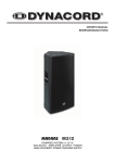
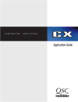
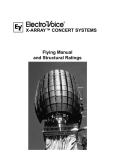
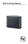
Sx600 User Manual Electro-Voice® Sx600 User Manual Table of Contents Product Description ................................................................................. 1 Important Features .................................................................................. 1 Product Feature Identification .................................................................. 2 System Acoustic Design Considerations ................................................. 3 Installation Precautions ............................................................................ 4 Installation Notes ..................................................................................... 4 Installation Procedure .............................................................................. 7 Step 1: Selection and Preparation of the Mounting Surface ..................... 7 Step 2: Mounting the SuperSAMTM Bracket .............................................. 7 Step 3: Completing the Electrical Connections ........................................ 7 Step 4: Mounting the Speaker and Aligning ............................................. 8 Step 5: System Adjustment and Acoustic Tuning ................................... 10 Appendix A: Troubleshooting ................................................................. 10 Appendix B: Warranty Statement ........................................................... 12 Appendix C: Technical Specifiations ...................................................... 13 TOC Electro-Voice® Sx600 User Manual Product Description The Sx600 Series is a remarkably flexible indoor/outdoor speaker system designed to produce high-fidelity high-level audio in distributed applications such as stadiums, racetracks, amusement parks, fairgrounds, etc. Utilizing a 65° x 65° high frequency horn and a unique 2-element vertical midbass array, Sx600 gives you the clarity of a direct radiator with the high SPL and directivity of a properly designed horn system, especially in the important vertical plane. While intended primarily for vocal applications, the Sx600 accurately reproduces music if heavy bass is not required. Important Features The Sx600 is available as either a conventional 4 ohm low impedance system, the Sx600PI, or as a constant voltage system, the Sx600PIX. The PIX version features a 100% duty cycle rated 600 watt full isolation line transformer for operation with 70volt, 100volt, 140volt, or 200volt distributed systems. The Sx600 comes with an all-new Super Strong Arm Mount, called the SuperSAMTM. This exclusive 2-part EV mounting system allows the installer to pre-set the exact down angle on the ground, fasten the separate mounting bracket by itself, and then mount the speaker to the bracket quickly and easily with a single bolt, setting the pan angle anywhere within a 180° arc in the process. The three-layer stainless steel grill design is an acoustically transparent yet effective barrier to both condensation and heavy rain. The lightweight polypropylene enclosure has strategically placed internal passages to conduct moisture that may accumulate internally out to the side channels where it drains away. Electro-Voice® Sx600 User Manual 1 Product Feature Identification Enclosure (Front View) Enclosure (Rear View) 65° x 65° VaripathTM Constant DirectivityTM HF Horn with DH2T Compression Driver Nd12A-8 Neodymium Midbass Driver White + DL12BFL Midbass/LF Driver Black - Weather-Resistant Lightweight Polypropylene Enclosure SJO Input Cable All Aluminum Rigging All Aluminum Rigging Full Face Stainless Steel Grille with Hydrophobic Backing (Not Shown) All Stainless Steel Hardware (Not Shown) SuperSAMTM Down Angle Adjustment (0°- 60° in 5° Increments) Stainless Steel SuperSAMTM Mounting Bracket Figure 1: Sx600 Product Features 2 Electro-Voice® Sx600 User Manual System Acoustic Design Considerations Direct radiator acoustic systems can offer great vocal band clarity but dont usually offer the efficiency and directivity of horn loaded systems. Horn loaded systems, if the overall dimensions are large enough, can offer great directivity control, but typical multi-way horn designs, particularly high Q co-axial designs, are also naturally resonant. Resonant systems suffer from poor time domain response and, as a consequence, can have poor intelligibility. The EV solution is to combine a two element critically spaced midbass line array with ultra-efficient neodymium magnetics. This produces the high SPL levels and vertical directivity of a properly horn loaded low/mid section while maintaining the clear vocal reproduction of a well damped direct radiator system. The Electro-Voice ND12A neodymium midbass driver developed for X-Array has been optimized for ultra high level, high intelligibility 300Hz to 2kHz response. The ND12A incorporates EVs Ring Mode Decoupling (RMD) technology to dampen mechanical domain resonances that color vocal fundamentals in normal direct radiator systems. RMD, found in most EV drivers, ensures level independent tonal response and produces a level of intelligibility unique to EV systems. The second 12 inch driver, a specially modified DL series, works with its own crossover section and critical spacing to the ND12A to greatly improve midband vertical directivity and system output below 300Hz. The result is clear, clean vocals, with the SPL capabilities required for large spaces. The SX600 also features EVs DH2T medium format compression driver coupled to our unique Varipath constant directivity high frequency horn. The HF horn pattern is optimized to a 65° horizontal by 65° vertical included angle to produce both long throw and wide front to back audience coverage. The high power handling and low distortion performance of the DH2T assures excellent vocal articulation with extended high frequency coverage to beyond 16kHz. Electro-Voice® Sx600 User Manual 3 Installation Precautions This document details general mounting practices appropriate to the entertainment industry, as they would apply to the mounting of ElectroVoice Sx600 loudspeaker systems. It is intended to familiarize the reader with mounting hardware and techniques for suspending Sx600 loudspeaker systems overhead. Only persons with the knowledge of proper hardware and safe mounting techniques should attempt to suspend any sound systems overhead. Prior to suspending any Electro-Voice Sx600 loudspeaker systems overhead, it is essential that the user be familiar with the strength ratings, mounting techniques and special safety considerations outlined in this manual. The mounting techniques and practices recommended in this manual are, of necessity, in general terms to accommodate the many variations in mounting configurations. As such, the user is expressly responsible for the safety of all specific Sx600 loudspeaker mounting configurations as implemented in practice. The Sx600 SuperSAMTM Mounting System is intented to support the Sx600 Speaker System only. Do not use it for any other purpose. Never set anything on, or hang anything from, the Sx600 SuperSAMTM when using it for the Sx600 Speaker System. Installation Notes The Sx600PI weighs in at 80 lb (36.3 kg.) and the Sx600PIX at 98 lb (44.5 kg). It is the installers responsibility to insure that the mounting surface is stable and sufficiently strong to support the weight of the unit(s) being mounted. The SuperSAMTM is made of tough 6061T6 aluminum, and the actual mounting bracket is stainless steel. DO NOT WELD. Consult and follow all applicable codes and procedures. Use only ½ inch diameter mounting bolts, 4 per bracket minimum. (all 6 is recommended) When mounting outdoors, remember to allow for wind, snow and ice load. Do not locate the Sx600 where it may be subjected to water or snow run-off from roofs, gutters, etc. NEVER MOUNT AN Sx600 ON ITS SIDE. 4 Electro-Voice® Sx600 User Manual Pole Mounting Follow the pole manufacturers recommendations when mounting to a pole. On wooden poles, make sure there is no rot or other deterioration. Through-bolts with backing plates are highly recommended. Lag bolts should only be used in conjunction with straps. 1/2 Bolts (6 Reqd) Approved Straps (4 Reqd) SuperSAMTM Bracket Figure 2: Pole Mounting Block Wall Mounting Do not attempt to mount an Sx600 to a block or brick wall without through-bolts and large, heavy steel backing plates on both sides of the wall. On poured concrete walls use deep ½ inch diameter anchors that cannot be pulled out once set. Use all 6 mounting holes. SuperSAMTM Bracket 1/2 Bolts (6 Reqd) Block Wall Heavy Steel Backing Plates Block Wall Figure 3: Block Wall Mounting Electro-Voice® Sx600 User Manual 5 Stud Wall Mounting First determine whether the structural members in the wall can withstand not only the weight of the Sx600, but also the side-to-side stresses of heavy cross-winds. Reinforce both sides of the wall with heavy plates, ¾ inch marine plywood minimum, and use through bolts. Never rely on lag bolts alone. Additional side-to-side support may be had by attaching simple steel outriggers (not included) from the SuperSAMTM pivot bolt to the next stud on either side of the mounting bracket. Never mount to a wall containing plaster or drywall without backing plates. 1/2 Bolts (6 Reqd) Stud SuperSAMTM Bracket Large Backing Plates, 3/4 Marine Plywood Min. Steel Outriggers Studs Figure 4: Stud Mounting I-Beam Mounting Because of the vast number of sizes and conditions of their use, consult a licensed structural engineer for the approved method of attaching an Sx600 to any particular I-Beam or other structural component. Mounting Surface Reinforcement If in doubt: Make It Stronger. Strong side winds will exert tremendous side leverage along the axis of the mounting bolts sufficient to crush some surfaces. A large backing plate and/or steel outriggers attached from the pivot bolt to the wall 16" to 24" either side of center makes a simple and effective reinforcement in most situations. 6 Electro-Voice® Sx600 User Manual Installation Procedure Step 1: Selection and Preparation of the Mounting Surface Surface must be clean and smooth. It must also be a material that is not easily crushed. While the SuperSAMTM distributes weight evenly over a relatively large area, strong winds against the side of the Sx600 will exert significant crowbar-like leverage between the bolts and the side corner edges of the bracket. For this reason, surfaces of plaster, drywall, soft wood, cinder block, ceramic, glass or other brittle, crushable materials must have a large heavy backing plate to prevent the Sx600 from loosening itself by crushing its mounting surface. Step 2: Mounting the SuperSAM Bracket If bolts are to be used, determine the exact location desired for the holes on the mounting surface. Use a center punch to mark the center of each hole to be drilled and minimize hole drift. Drill holes and DE-BURR. The bracket MUST sit perfectly flat against the mounting surface. Mount the bracket using ½ bolts, washers, lock washers and nuts, and tighten securely. Stainless Steel hardware is recommended. Step 3: Mounting the Speaker and Aligning Pre-set the down angle of the speaker (as pre-determined by EASE) by inserting the 5/16" Stainless Steel bolt through the appropriate holes (See Figure 5). Tighten it and the ½ pivot bolt securely. (If aiming visually, tighten bolts finger-tight only until aiming is finalized.) Place the long ½ bolt and washer through the appropriate hole in the mounting bar. Use the hole nearest the speaker for down-angles of less than 40 degrees and the farthest hole for angles greater than 40 degrees. Set the speaker on the already mounted bracket end bar, dropping the ½ pivot bolt through the hole near the end of the bar. (The second hole is provided as a convenience for certain close in situations.) Install the flat washer, lock washer and nut and tighten just enough to pull both bars together. Determine pan angle by sighting along center groove of enclosure. (Either top or bottom) Securely tighten pivot bolt to lock in place. Visually check down angle. Too high an angle will result in poor intelligibility in the nearfield; a too-low angle will cause poor intelligibility far-field and a hot spot close in. If necessary, re-set the down-angle as follows: Loosen the ½ bolt on the adjusting bracket and remove the 5/16" bolt. Tilt the speaker to the desired angle and re-insert the 5/16" bolt in the appropriate hole. Re-tighten all hardware. Electro-Voice® Sx600 User Manual 7 Exploded View Fully Assembled View Figure 5: Mounting the Speaker to the Wall Bracket Step 4: Completing the Electrical Connections Trim the SJO cord to a neat length while allowing enough slack for future aiming adjustments or service. Make electrical connections per all applicable codes in a weather-tight box and secure the SJO cord through a weather-tight gland nut. Observe color code for proper polarity: Black wire from speaker is audio (-), white wire is audio (+). Using the PIX (Constant Voltage Version) Constant Voltage Design Considerations One of the major expenses of any large sound system up-grade is the cost of running new wiring. For this reason, the Sx600PIX transformer has taps for use on lines as high as 200volts, which is easily delivered by an Electro-Voice CPS-4 amplifier in bridge mode. Keeping the current draw the same, changing from 70volts to 200volts means you can now pull approximately 3 times the wattage from the same wiring! In new installations, the higher voltages mean less line loss on long runs, less current and lighter gauge wire. Always check and comply with all applicable codes. 8 Electro-Voice® Sx600 User Manual Selecting Wattage Taps The Sx600 is intended to be a high level speaker, so the transformer taps are set up to produce a full 600 watts at each of the 4 voltages listed. If necessary, the wattage may be halved by selecting the next HIGHER voltage tap. NEVER select a tap for a LOWER voltage! (i.e; Do not use a 70 volt tap in a 100 volt system, etc.) The Sx600PIX is shipped from the factory pre-wired for 600 watt operation on standard 70 volt lines. To select a higher voltage, remove the 10 mounting screws around the perimeter of the input panel (See Figure 6). CAUTION: the transformer alone weighs 18 lb. (8.2 kg.) Be prepared to support this weight when the screws come out! Carefully tip the panel outward from the enclosure, taking care not to damage the water gasket or strain any of the internal connecting wires. Locate the WHITE wire of the input cord and carefully pull its connector straight back off the 70 volt tab. Select the desired voltage and push the connector securely onto the corresponding tab. Do NOT move the black wire, which must stay connected to COM. Inspect the water gasket for dirt or damage, and reassemble the panel to the enclosure. Using a permanent marker, MARK THE NEW VOLTAGE SETTING in the box provided on the Sx600PIX label. Top of Panel Voltage Tap Selector (White Wire) COM Connection (Black Wire Do Not Move!) Exterior View Mounting Screws (10 Places) Plug-In Connector from Transformer Interior View Figure 6: Selecting Wattage Taps Electro-Voice® Sx600 User Manual 9 Step 5: System Adjustment and Acoustic Tuning The Sx600 MUST BE HI-PASSED at 90Hz using a minimum slope of 12dB/octave with a Q of 1.6. (Easily obtainable on the Electro-Voice Dx38 Digital Loudspeaker Controller) If analog filtering is used, a 70Hz high-pass filter of at least 12dB/octave slope and low frequency EQ of NO MORE THAN 3dB boost centered at 90 or 100Hz not to exceed one octave wide is acceptable. Do not use shelving EQ! Set the system limiters to prevent amplifier clipping even during extreme (aka: excited announcer) program peaks. EQ cuts are acceptable when necessary to account for resonances within the venue, but DO NOT BOOST EQ. The Sx600 has a full, natural sound, but has no usable output below 70 Hz. Appendix A: Troubleshooting Every Sx600 is thoroughly tested before it leaves the Electro-Voice factory. Listed below are some of the common problems that may be encountered along with suggestions for solving them. Speaker plays but level is low: 1.) Make sure the amplifier is capable of delivering sufficient voltage and current to produce the wattage necessary for the total number of systems per line. 2.) Check amplifier input drive signal level and gain adjustment. Verify that amplifier is developing the required output voltage and that the voltage at the loudspeaker is the same. 3.) Excessive line loss. Verify that wire size is adequate for the length of run, especially on 4 ohm PI models. If wire gauge is too small, either rewire, change to the constant-voltage PIX version, or on PIX models, change to a higher voltage tap to reduce line loss, providing the amplifier is able to deliver that voltage without clipping and the wiring will still meet code requirements at the higher voltage. 4.) Incorrect voltage tap setting. (PIX models only) Setting the tap higher than the line voltage will reduce the wattage drawn from the line, resulting in 3dB less level (1/2 the wattage) for each tap above rated voltage. Verify and re-set taps as necessary. Setting the taps below the line voltage (PIX models) or attempting to drive too low an impedance (PI models) may cause the amplifier to go into over-current protection resulting in decreased output. Redistribute lines and/or add more/higher power amplifiers. 10 Electro-Voice® Sx600 User Manual System shuts down when driven hard. 1.) Insufficient amplifier power. Amplifier goes into protect mode due to overcurrent or thermal stress. Switch to a larger amplifier. 2.) Line impedance too low. (PI models in particular) Some amplifiers will not drive a 2 ohm load at full power, especially if both channels are loaded to 2 ohms. (A pair of Sx600PI systems on the same line is a 2 ohm load.) Use a different/ bigger amplifier, convert to PIX versions, or reconfigure lines with more amp channels and fewer speakers per line. 3.) Incorrect high-pass filter or no filter at all. All Sx600 models MUST BE HI-PASSED, (See step 5 above) but PIX models may cause amplifier shut-down due to transformer saturation at high levels caused by low frequency transients or heavy bottom octave program content. Verify that the CORRECT hi-pass filtering is in use at all times. 4.) Amplifier is simply being overdriven and going into protect mode. With an oscilloscope on the amplifier output, adjust compressor/ limiter to keep amplifier(s) out of clipping. If the system has no comp/limiter, add one to the signal chain and be sure it is properly set. Inconsistent intelligibility in audience area 1.) Improper aiming. If intelligibility decreases near the speaker, the down-angle is set too high. If the intelligibility is great right under the speaker but suffers as you begin to move away from it, the down-angle is set too low. Intelligibility across the horizontal plane (side to side) can be affected by a sloping audience area, reflections from nearby walls or other barriers, and trees, banners and other objects obstructing and/or reflecting the sound in an adverse way. EASE is an excellent tool for predicting the correct aiming, but in actual use these angles may need to be adjusted. 2.) Over-equalization. The primary speech fundamentals are found in the 300Hz to 3kHz range, most consonants are affected by the 3kHz to 6 kHz band, and sibilance is mostly from 6kHz on up. Substantial EQ cuts in any of these regions will seriously degrade the intelligibility of speech. Use only enough EQ to tame the very worst room resonances (which should not be a problem outdoors) keeping the notch width as narrow as possible. The best solution is to keep the announcer close to Electro-Voice® Sx600 User Manual 11 the microphone and use a good compressor/limiter to compensate for variances in microphone distance and excitement. Appendix B: Warranty Statement Electro-Voice® products are guaranteed against malfunction due to defects in materials or workmanship for a specified period, as noted in the individual product-line statement(s) below, or in the individual product data sheet or owners manual, beginning with the date of original purchase. If such malfunction occurs during the specified period, the product will be repaired or replaced (at our discretion) without charge. The product will be returned to the customer prepaid. Exclusions and Limitations The Limited Warranty does not apply to: (a) exterior finish or appearance; (b) certain specific items described in the individual product-line statements below, or in the individual product sheet or owners manual; (c) malfunction resulting from use or operation of the product other than as specified in the product data sheet or owners manual; (d) malfunction resulting from misuse or abuse of the product; or (e) malfunction occurring at any time after repairs have been made to the product by anyone other than Electro-Voice® Service or any of its authorized representatives. Obtaining Warranty Service To obtain warranty service, a customer must deliver the product, prepaid, to Electro-Voice® Service or to any of its authorized service representatives, together with proof of purchase of the product in the form of a bill of sale or receipted invoice. A list of authorized service representatives is available from Electro-Voice® Service at: 12000 Portland Avenue, Burnsville, MN 55337. Ph: (877) 863-4166. Incidental and Consequential Damages Excluded Product repair or replacement and return to the customer are the only remedies provided to the customer. Electro-Voice® shall not be liable for any incidental or consequential damages including, without limitation, injury to persons or property or loss of use. Some states do not allow the exclusion or limitation of incidental or consequential damages, so the above limitation or exclusion may not apply to you. Other Rights This warranty gives you specific legal rights, and you may also have other rights which vary from state to state. Speakers and Electronics Electro-Voice® Speakers and Speaker Systems are guaranteed against malfunction due to defects in materials or workmanship for a period of five (5) years from the date of original purchase. The Limited Warranty does 12 Electro-Voice® Sx600 User Manual not apply to burned voice coils or malfunctions such as cone and/or coil damage resulting from improperly designed enclosures. Electro-Voice® active electronics associated with the speaker systems are guaranteed for three (3) years from the date of original purchase. Additional details are included in the Uniform Limited Warranty statement. Appendix C: Technical Specs Freq. Range (-3 dB): 100 Hz - 14 kHz Freq. Range (-10 dB): 70 Hz - 16 kHz Max Calculated SPL: 139 dB Horizontal Coverage: 65° Nominal Ver tical Coverage: 65° Nominal Power Handling: 600 Watts Cont., 2400 Watts Peak Sensitivity (SPL 1W/1m): 105 dB Impedance: 4 ohms (Nominal), 3.5 ohms (Min.) Crossover Frequency: 1.8 kHz, LF/MB Overlap: 200-600 Hz Recommended Filtering: 90 Hz Highpass Filter, @ Q=1.6 Recommended Amplifier : EV CPS Series Connectors: SJO Cable with Gland Nut Enclosure Material: High Density Polymer "PIX" Version Wattage 70V - 75, 150, 300, 600W Taps: 100V - 150, 300, 600W 140V - 300, 600W 200V - 600W Mounting: SuperSAMTM, 5° Increments over 60° Ver tical, 180° Horizontal, can be Bolted or Strapped Grille: Powder coated Stainless Steel Weather Resistance: IEC 529 IP 44, Mil Spec 810 humidity, salt spray, temperature, and UV Dim (H x W x D): 45.8" x 16.9" x 12.3" (1163mm x 429mm x 312mm) Net Weight (with Bracket): Sx600PI - 80.0 lbs (36.3 kg) Sx600PIX - 98.0 lbs (44.5 kg) Shipping Weight: Sx600PI - 92.0 lbs (41.8 kg) Sx600PIX - 110.0 lbs (50.0 kg) Electro-Voice® Sx600 User Manual 13 U.S.A. and Canada: For customer orders, contact the Customer Service department at: 800/392-3497 Fax: 800/955-6831 For warranty repair or service information, contact the Service Repair Department at: 800/685-2606 For technical assistance, contact Technical Support at: 866/78-AUDIO Specifications subject to change without notice. All Other International Locations: 952-884-4051 Fax: 952-736-4212 www.electrovoice.com l Telex Communications, Inc. l Printed in U.S.A © Telex Communications, Inc. 3/2003 Part Number 38110-208 Rev B www.telex.com Electro-Voice® Sx600 User Manual