1
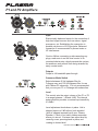
Plasma Series High Powered Loudspeaker Owners Manual - P1 (Left & Right) - P2ELECTRO-VOICE Subwoofer Plasma Owners Manual ® Important Safety Instructions The lightning flash with arrowhead symbol, within an equilateral triangle is intended to alert the user to the presence of uninsulated “dangerous voltage” within the product’s enclosure that may be of sufficient magnitude to constitute a risk of electric shock to persons. The exclamation point within an equilateral triangle is intended to alert the user to the presence of important operating and maintenance (servicing) instructions in the literature accompanying the appliance. 1. Read these instructions. 2. Keep these instructions. 3. Heed all warnings. 4. Follow all instructions. 5. Do not use this apparatus near water. Do not expose this apparatus to dripping or splashing and ensure that no objects filled with liquids, such as vases, are placed on this apparatus. 6. Clean only with a dry cloth. 7. Do not block any of the ventilation openings. Install in accordance with the manufacturers instructions. 8. Do not install near any heat sources such as radiators, heat registers, stoves, or other apparatus (including amplifiers) that produce heat. 9. Only use attachments/accessories specified by the manufacturer. 10. Refer all servicing to qualified service personnel. Servicing is required when the apparatus has been damaged in any way, such as power-supply cord or plug is damaged, liquid has been spilled or objects have fallen into the apparatus, the apparatus has been exposed to rain or moisture, does not operate normally, or has been dropped. 11.To completely disconnect AC power from this apparatus, the power supply cord must be unplugged. For US and CANADA only: Do not defeat the safety purpose of the grounding-type plug. A grounding type plug has two blades and a third grounding prong. The wide blade or the third prong are provided for your safety. When the provided plug does not fit into your outlet, consult an electrican for replacement of the absolete outlet. Important Service Instructions CAUTION: These servicing instructions are for use by qualified personnel only. To reduce the risk of electric shock, do not perform any servicing other than that contained in the Operating Instructions unless you are qualified to do so. Refer all servicing to qualified service personnel. 1. Security regulations as stated in the EN 60065 (VDE 0860 / IEC 65) and the CSA E65 - 94 have to be obeyed when servicing the appliance. 2. Use of a AC separator transformer is mandatory during maintenance while the appliance is opened, needs to be operated and is connected to the AC. 3. Switch off the power before retrofitting any extensions, changing the AC voltage or the output voltage. 4. The minimum distance between parts carrying AC voltage and any accessible metal piece (metal enclosure), respectively between the AC poles has to be 3 mm and needs to be minded at all times. The minimum distance between parts carrying AC voltage and any switches or breakers that are not connected to the AC (secondary parts) has to be 6 mm and needs to be minded at all times. 5. Replacing special components that are marked in the circuit diagram using the security symbol (Note) is only permissible when using original parts. 6. Altering the circuitry without prior consent or advice is not legitimate. 7. Any work security regulations that are applicable at the location where the appliance is being serviced have to be strictly obeyed. This applies also to any regulations about the work place itself. 8. All instructions concerning the handling of MOS - circuits have to be observed. Note: 1 SAFETY COMPONENT (HAS TO BE REPLACED WITH ORIGINAL PART ONLY) ELECTRO-VOICE® Plasma Owners Manual Table of Contents Important Safety/Service Instructions........................................................................................... 1 Plasma Series Owner’s Manual ................................................................................................... 2 Safety First ................................................................................................................................... 3 Description ................................................................................................................................... 4 System Features - Plasma ........................................................................................................... 4 System Setup ............................................................................................................................... 4 P1 and P2 Amplifiers .................................................................................................................... 5 Setup Diagrams for Plasma ......................................................................................................... 7 Using Plasma P1’s as Floor Monitors .......................................................................................... 8 Plasma P1 Rigging ....................................................................................................................... 8 Suspending Plasma P1 Speaker Systems ................................................................................... 9 Specifications ............................................................................................................................. 10 Dimensions (Plasma P1) ............................................................................................................ 10 Dimensions (Plasma P2 Subwoofer) ........................................................................................... 11 Block Diagrams .......................................................................................................................... 12 Notes .......................................................................................................................................... 13 Plasma Series Owner’s Manual Thank you for choosing Electro-Voice® Plasma high powered loudspeaker systems. These systems are the culmination of EV’s 75 years of experience in transducer design and over 50 years of experience in designing and building electronics. Please take time to consult this manual so that you can understand all the features built into your EV systems and fully utilize all their performance capabilities. ELECTRO-VOICE® Plasma Owners Manual 2 Safety First When setting up, installing and using Electro-Voice® Plasma speaker systems, there are a number of precautions that you should follow: · When Electro-Voice® Plasma speakers are used for portable applications in which they will be stacked directly on the floor, make sure that the floor or stage is solid and secure. Make sure to: · Route cables and position the stand so that performers, production crew and audience members will not trip over the stand or cables and pull the speaker system over. Secure cables with wire ties or tape whenever possible. · If you intend to hang or fly the Plasma two-way systems, only do so safely with the correct hardware and accessories. WARNING: Suspending any object is potentially dangerous and should only be attempted by individuals who have a thorough knowledge of the techniques and regulations of rigging objects overhead. Electro-Voice® strongly recommends that Plasma speakers be suspended taking into account all current national, federal, state and local regulations. It is the responsibility of the installer to ensure that Plasma speakers are safely installed in accordance with all such regulations. If Plasma speakers are suspended, Electro-Voice® strongly recommends that the system be inspected at least once a year. If any sign of weakness or damage is detected, remedial action should be taken immediately. There are data sheets for each EV hanging hardware part that should also be consulted prior to suspending speakers. · Electro-Voice® does not recommend use of Plasma speakers outdoors without protection from rain or in high moisture environments. · Electro-Voice® Plasma loudspeakers are easily capable of generating sound pressure levels sufficient to cause permanent hearing damage to anyone within normal coverage distance. Caution should be taken to avoid prolonged exposure to sound pressure levels exceeding 90 dB. 3 ELECTRO-VOICE® Plasma Owners Manual Description Electro-Voice® Plasma high powered loudspeakers are fully integrated audio systems with carefully matched electronics and transducers. These products make it easy to setup a highquality sound system quickly with a minimum of cables and external electronics. It retains typical EV ruggedness, reliability and impeccable sound quality. System Features - Plasma · Two built-in power amplifiers, one for low frequencies and one for high frequencies. The amplifiers also contain electronic crossover circuitry and CD horn compensation optimized for the speaker components a well as a limiter circuit that prevents either amplifier from clipping while preserving the sonic quality. · The low-frequency power amplifier delivers 500 watts continuous average power. · The high-frequency power amplifier delivers 150 watts continuous average power. · The subwoofer power amplifier delivers 800 watts continuous average power. · The line input utilizes Neutrik “combo” connectors, which will accept either ¼-inch or 3-pin XLRtype connectors. · The separate line output is 3-pin XLR-type balanced, low-impedance output that can be used with long cable runs. · The Plasma P1 two-way system is perfect for use as powered floor monitors. · Neutrik Powercon connectors are used for AC power connections. They provide a positive locking feature to prevent accidental disconnection. System Setup To get your Plasma system into operation as quickly as possible, please observe the following steps and precautions. · Plug the 3-terminal Powercon ac cable into a grounded line receptacle. Extension cords can be used to lengthen the ac cable as necessary but make sure that they are 3-conductor 14 gauge or greater, and that are properly grounded to avoid electrical hazards and extraneous noise. · Be sure that the Plasma system is plugged into an ac power source that is capable of supplying the correct voltage. If the line voltage drops too much, the built-in amplifiers won’t be able to develop their rated power and sound quality will suffer. Under high signal conditions, the Plasma amplifier section can pull 3 – 4 amps of current (120 volt models) (2 amps at 240 volts). That means that no more than 4-Plasma systems should be plugged into a single 15 amp electrical service. Be cautious of what else is plugged into the same electrical service line to avoid electrical problems and poor performance. · BEFORE TURNING THE POWER ON, MAKE SURE THAT THE LEVEL CONTROLS ARE DOWN TO AVOID TRANSIENTS OR UNEXPECTED LOUD SOUND. Turn on the power switch and ensure that the system is receiving power by monitoring the status LED. If the system is receiving signal, the LED will illuminate green. ELECTRO-VOICE® Plasma Owners Manual 4 P1 and P2 Amplifiers Input Electronically balanced inputs for the connection of high-level signal sources such as mixers, signal processors, etc. Establishing the connection is possible via phone or XLR-type jacks. Balanced connection is recommended to prevent noise or HF-interference. Caution: Before connecting or disconnecting any plugs, make sure to set the level control to its counterclockwise stop, which prevents the system, the audience and yourself from being stressed by nasty contact noise. Outputs Output is full bandwidth pass through. Crossover Mode Switch Selects between 40 Hz highpass filter for Fullrange use, and 100 Hz highpass filter for use with Plasma P2 subwoofer. It is not recommended that you use your P1 in Fullrange with subwoofers. Level This control sets the output volume of the P1 or P2 in a range between -∞dB and +6dB. The internal power amplifier provides a nominal input sensitivity of +6dBu. Level adjustment knob shown in place. Unit is shipped preset at 0 dB without knob installed (knob is shipped separately with your Plasma Speaker). If knob is not used, please remember where you store it. Customer can adjust level by removing cover, pressing knob in place, and rotating to desired level. 5 ELECTRO-VOICE® Plasma Owners Manual Status Indicators These indicators provide information about the actual operational state of the Plasma’s internal power amplifier. Signal Indicates that an audio signal is present at the input and that it is output. Limit When lit this indicator signals that the internal power amplifier actually operated at the threshold of clipping. Short-term blinking is not critical, because the amp’s audio limiter keeps distortion under control, so that the sound is unaffected. Input overdrive, which results in sound degradation, is a probable cause for a continuously lit indicator. To prevent this from happening, reduce the input level. Protection There are two leds to indicate Speaker Protection, or Amplifier Protection. When Speaker is lit the voice coil protection circuit is in operation to prevent over powering the voice coil. Short term blinking indicates high average power of the program signal, sound is not affected. Amplifier indicates the amplifier thermal protection is engaged, this shuts down the amplifier and its sound output. It will reset automatically when its operating temperature is safe. If it occurs check the heatsink location to make sure it in a normal environment. It should not be in the path of very hot air. Power Switch AC switch for switching the Plasma’s power ON or OFF. The switch lights after turning the power ON. Make sure that the AC cord is correctly connected if the switch is not lit upon turning the power on. If the AC cord is correctly connected and the AC switch does not light upon power-on, please contact your local dealer. AC Fuse During normal operation the AC fuse of the Plasma only blows at the occurrence of a malfunction. Exchanging the fuse is only permissible using a fuse of the same type (current, voltage and release characteristic). In case the fuse blows frequently, please contact your local dealer. AC Connector AC connection is established via a PowerCon connector. A 15’ (5m) long AC cord with PowerCon plug is supplied. CAUTION: THIS APPLIANCE HAS NO USER-SERVICABLE PARTS INSIDE. LEAVE ANY SERVICING AND MAINTENANCE QUALIFIED SERVICE TECHNICIANS ONLY. ELECTRO-VOICE® Plasma Owners Manual 6 Figure 1a: Rear Panel Plasma P1 Figure 1b: Rear Panel Plasma P2 Setup Diagrams for Plasma · Plug a line input into either the ¼-inch or the 3-pin XLR-type input connector. The ¼- inch input is in the center of the XLR connector and can accept unbalanced or balanced lines (TRS ¼-inch). The line input level required to drive the unit to full power is from – 12 dBu to 0 dBu. The system’s level control regulates the overall output level of the system. 7 ELECTRO-VOICE® Plasma Owners Manual Using Plasma P1’s as Floor Monitors · The Plasma P1 is perfect for use as a powered floor monitor. Figure 2: Using the Plasma P1 as a mirror image Floor Monitor Plasma P1 Rigging · The Plasma P1 has an L-track embedded into the top and side of the enclosure to provide convenient multi axis suspension and attachment points for an optional suspension arm or L-track stud fitting. The very compact multi-angle enclosure can be suspended or arrayed. The L-Track also accepts double-stud locking swivel fittings. Figure 3: Rigging Hardware for the Plasma P1 Figure 4: Suspending the Plasma P1 WARNING: Suspending any object is potentially dangerous and should only be attempted by individuals who have a thorough knowledge of the techniques and regulations of rigging objects overhead. Electro-Voice® strongly recommends that Plasma speakers be suspended taking into account all current national, federal, state and local regulations. It is the responsibility of the installer to ensure that Plasma speakers are safely installed in accordance with all such regulations. If Plasma speakers are suspended, ElectroVoice® strongly recommends that the system be inspected at least once a year. If any sign of weakness or damage is detected, remedial action should be taken immediately. ELECTRO-VOICE® Plasma Owners Manual 8 Suspending Plasma P1 Speaker Systems P1 enclosures have L-track located on the top, bottom, and on one side. Single or double stud ring fittings can be attached to the L-track to be used as suspension points. These points are located at the center of gravity to allow the system to hang straight when used either vertically, or horizontally. Plasma P1 is NOT designed to be suspended vertically from one another. More than one system should never be suspended from a single point! Working load limits for the enclosure, and fittings are shown below in Figure 5. Plasma P1 enclosures have been pull tested and exceed a safety factor of 10 to 1. Figure 5: Working Load Limit Rating of Plasma P1 Powered Speaker System Prior to each use, inspect the grid assembly or suspension point(s) and associated hardware for any cracks, deformations, broken welds, corrosion, missing or damaged components which could reduce the grid assembly or suspension point(s) strength. Replace any damaged hardware. Never exceed the limitations or maximum recommended load intended for grid assembly design or suspension point(s). As an added safety measure, it is suggested that the user install a second suspension point back to the grid (or building structural supports). This redundant safety point should have as little slack as possible (less than one inch is preferable). Prior to each use, inspect the loudspeaker enclosures for any cracks, deformations, missing or damaged components, which could reduce enclosure strength. Inspect the track and bracket assembly on the enclosures for any cracks, deformations, missing or loose screws which could reduce the flying hardware strength. Replace any loudspeaker systems that are damaged or missing hardware. Never exceed the limitations or maximum recommended load for the Plasma systems. 9 ELECTRO-VOICE® Plasma Owners Manual Specifications Plasma P1 Plasma P2 Freq. Response (-3 dB): 45 Hz - 17 kHz Freq. Response (-3 dB): 40 Hz - 100 Hz Freq. Range (-10 dB)1: 38 Hz - 19 kHz Freq. Range (-10 dB)1: 30 Hz - 110 Hz Calculated Max SPL: 132 dB Calculated Max SPL: 132 dB Horizontal Coverage: 80° Amplifier Design: Class H Vertical Coverage: 55° THD: < 0.05% Amplifier Design: Class H Input Impedance: 20K Ω THD: < 0.01% Amplifier Power: 550 W RMS (800W Peak) Input Impedance: 20K Ω Low-Pass Crossover: 100 Hz LF Amplifier Power: 460 W RMS (550W Peak) HF Amplifier Power: 140 W RMS (150W Peak) High-Pass Crossover 100 Hz (Switchable): Level Control: - θ to +6 dB Input Sensitivity: +6 dB for full output Transducer: 18" (460 mm) EVX180B Level Control: - θ to +6 dB Input Sensitivity: +6 dB for full output LF Transducer: 15" (381 mm) EVX155RMD HF Transducer: 1.4" (35.6 mm) exit ND6 Comp. Driver Connectors: Balanced Line Inputs: XLR and ¼" phone Combination Balanced Output: XLR Power Requirement: 100, 120, 230, or 240 VAC, 50-60Hz Enclosure Material: 13-ply Birch Plywood Cabinet Finish: Futura Grille: Powder Coated Steel with Cloth Dim (H x W x D): 24.2" x 18.8" x 15.7" (615 x 476 x 400 mm) Connectors: Balanced Line Inputs: XLR and ¼" phone Combination Balanced Output: XLR Power Requirement: 100, 120, 230, or 240 VAC, 50-60Hz Enclosure Material: 13-ply Birch Plywood Cabinet Finish: Futura Grille: Powder Coated Steel with Cloth Hardware Included: Casters; Pole Mounting Flange Dim (H x W x D): 35.8" x 18.8" x 23.6" (910 x 476 x 600 mm) Net Weight: 140 lbs (63.6 kg) Shipping Weight: 150 lbs (68.1 kg) Net Weight: 93 lbs (42.3 kg) Shipping Weight: 99 lbs (45.0 kg) Dimensions (Plasma P1) Side View Top View Top View Front View Front View Plasma P1L (Left Version) ELECTRO-VOICE® Plasma Owners Manual Side View Plasma P1R (Right Version) 10 Dimensions (Plasma P2 Subwoofer) Top View Front View Side View Plasma P2 Subwoofer 11 ELECTRO-VOICE® Plasma Owners Manual Block Diagrams Plasma P1 Plasma P2 ELECTRO-VOICE® Plasma Owners Manual 12 Notes 13 ELECTRO-VOICE® Plasma Owners Manual Notes ELECTRO-VOICE® Plasma Owners Manual 14 U.S.A. and Canada: For customer orders, contact the Customer Service department at: 800/392-3497 Fax: 800/955-6831 For warranty repair or service information, contact the Service Repair Department at: 800/685-2606 For technical assistance, contact Technical Support at: 866/78 AUDIO Specifications subject to change without notice. All Locations: 952-884-4051 Fax: 952-884-0043 www.electrovoice.com l Telex Communications, Inc. l www.telex.com Printed in U.S.A © Telex Communications, Inc. 12/2003 Part Number 38110-323 Rev A ELECTRO-VOICE® Plasma Owners Manual