1
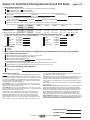
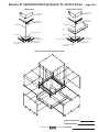
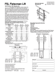
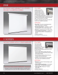
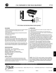
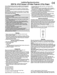
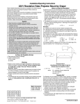
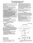
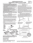
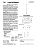
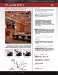
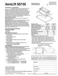
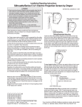
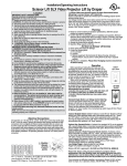
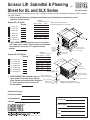
Scissor Lift Submittal & Planning
Sheet for SL and SLX Series
by
U.S. Patent D395,909
Planning sheet submission required with your order or request for quotation. Please mark appropriate response to each numbered
item (front and back)
➀ Select one model based on the maximum exact distance you need the projector to descend from “store”
position to “service” position.
Scissor Lift—SL Series
Quantity
4 ft.—Model SL4
5 ft.—Model SL5
6 ft.—Model SL6
7 ft.—Model SL7
8 ft.—Model SL8
9 ft.—Model SL9
Model
SL4
SL5
SL6
SL7
SL8
SL9
SL10
Maximum
Lowering Retracted
Distance Height 1
4'
81/8"
5'
91/8"
6'
101/8"
7'
111/8"
8'
121/8"
9'
131/8"
10'
141/8"
1
SMS Low Profile Mount adds 47/8",
including universal bracket, to unit height.
23½"
23"
20¾"
20¾"
9
/16" dia.
mounting holes
10 ft.—Model SL10
➁ FOR SL SERIES ONLY: Standard, factory set “show” position
is 18" below “store” position. “Show” position can be adjusted
after installation. If more than 24" is required, list show
position:
Scissor Lift—SLX Series
Quantity
11 ft.—Model SLX11
12 ft.—Model SLX12
13 ft.—Model SLX13
14 ft.—Model SLX14
15 ft.—Model SLX15
16 ft.—Model SLX16
Model
SLX11
SLX12
SLX13
SLX14
SLX15
SLX16
SLX17
Maximum
Lowering Retracted
Distance Height 1
11'
13¾"
12'
15¾"
13'
15¾"
14'
171/8"
15'
171/8"
16'
191/8"
17'
191/8"
See chart
(shown slightly
lowered)
Space for
projector's
ceiling
mounting
bracket
Fail-safe inertial
safety belt system
Space for projector
Pair of 1/8" aircraft cables
Optional ceiling
closure panel
2"
27
"
29
¾"
24
½"
26
¾"
9/16" dia.
mounting holes
See chart
(shown slightly lowered)
17 ft.—Model SLX17
➂ FOR SLX SERIES ONLY: Standard, factory set
Fail-safe inertial
safety belt system
Space for projector's
ceiling mounting bracket
“show” position is 36" below “store” position.
“Show” position can be adjusted after installation.
For “show” position of more or less than 36",
list show position.
Pair of 3/16" aircraft cables
Space for projector
Optional ceiling
closure panel
1
2"
SMS Low Profile Mount adds 47/8",
including universal bracket, to unit height.
(Continued on Page 2)
DRAPER SALESPERSON:
CUSTOMER CONTACT:
DEALER NAME:
SIGNATURE:
®
PROJECT NAME:
P.O. #:
DATE:
Copyright © 2008 Draper Inc. Form ScissorLift_Sub-PlanSheet08 Printed in U.S.A.
Scissor Lift Submittal & Planning Sheet for SL and SLX Series
page 2 of 4
➃ Select Optional Accessories
Optional Ceiling Access Door (2 x 2) to allow access above finished ceiling (highly recommended)
White Painted Finish
Accepts Ceiling Tile
Optional SMS Low Profile Mount and Universal Bracket
A) If you selected the SMS Low Profile Mount please provide the following Projector information (supplied by others)
Manufacturer
Make/Model
Projector Size H x W x L:
Optional plenum housing: optional ceiling closure panel not included.
B) If you selected the plenum housing option please provide the following information:
Projector Size H x W x L:
Bracket height:
Available space above ceiling:
Optional ceiling closure panel.
Optional ceiling finish kit: consists of ceiling closure panel and mating trim kit to finish ceiling opening.
C) If you selected one of the above options please use the following chart to select the correct size plenum housing, ceiling closure, or ceiling finish kit:
Size B
Size S
Size E
Size J
Size G
Size U
(SL Only)
(SL Only)
Max. Projector Size W x L
25" x 25"
25½" x 27½" 25½" x 35½" 25½" x 39½" 31½" x 44½"
27½" x 30½"
Ceiling Opening W x L
297/8" x 297/8"
29½" x 32"
29½" x 40"
29½" x 44"
357/8" x 49"
367/8" x 367/8" (Trim edge–to–edge)
Ceiling Closure Panel W x L 305/16" x 305/16"
30" x 32½"
30" x 405/8"
30" x 44½" 363/8" x 49½"
373/8" x 373/8" (Trim edge–to–edge)
➄ Do you want the optional factory installed hookup for RGB, Video and Projector Control?
A
What type of connectors do you need on Inputs (to Projector)?
BNC
How Many?
15 Pin HD
How Many?
RCA
How Many?
S-Video
How Many?
RS232 (DB9) How Many?
Yes
No
What type of connectors do you need on Outputs (to Lift)?
BNC
How Many?
15 Pin HD
How Many?
RCA
How Many?
S-Video
How Many?
RS232 (DB9) How Many?
➅ Select Voltage:
110-120V
220-230V
➆ Select Controls: This unit comes with one 12v Toggle Switch and 12v Momentary Key Control. For other switching
options, please select from below:
Optional Video Interface Control (VIC12) for projection screen operation
Optional Key Operated Power Supply Key Switch (On-off)
Optional Low Voltage Control (LVC-III)—24V*
Specify number of switches (LVC-S)
(Controls the "Show" position only)
*This is required for any of the following options:
Wireless Remote Control (radio frequency transmitter & receiver) (Controls the "Show" position only)
Wireless Remote Control (infrared transmitter & receiver) (Controls the "Show" position only)
➇ Will this unit be controlled by other equipment?
No.
Yes. What kind of equipment?
Specifications—Scissor Lift
video projector lifts, Model (SL4/SL5/SL6/SL7/SL8/SL9/SL10/SLX11/
SLX12/SLX13/SLX14/SLX15/SLX16/SLX17), for projectors weighing up to 350#.
Dove grey baked powder coat finish. Projector bolts onto operating pan, or mounts
to pan with optional SMS Low Profile Lift Bracket (projectors through 26 lbs only).
Electrically operated 110-120V AC, 60 Hz. UL recognized gearmotor, with metal
chain drive system, to be lifetime lubricated.
For SL Models: Projector to be suspended from 2¾" x 20" x 20" x 11 ga. steel
pan supported by steel scissor arms and operated by two 1/8" aircraft cables with
2000 foot/pounds tensile strength per cable.
For SLX Models: Projector to be suspended from 31/4" x 24" x 26" x 11 ga. steel
pan supported by steel scissor arms and operated by two, 3/16" aircraft cables with
4200 foot/pounds tensile strength per cable.
Equipped with 3 sets of stabilizing scissors, positioned on the left, right, and
rear sides. Also equipped with fail-safe inertial safety belt system and Cable
Management System with projector power cord. Factory set limit switches to
automatically stop travel at store, show, and service positions. Single Station
Control, standard, consists of one 12V toggle switch to lower lift from “stored” to
“show ” positions, and one 12V momentary key switch to lower lift from “show” to
“service” position. Optional LVC-III for operation from “stored” to “show” positions
only; required for use with Key Operated Switch.
Optional plenum housing consists of suitable painted steel panels for use in return
air plenum situations. Optional ceiling closure panel, finished in white baked
textured powdercoat, shall descend smoothly with projector. Choose a model
based on number of feet needed (4'-9'/11'-17') to put projector within easy reach
for servicing.
Please Note: The Scissor Lift should be specified in conjunction with a DRAPER
motorized screen.
SMS Low Profile Fixed Mount: Ceiling mount shall consist of a steel ball joint and
Universal Projector Bracket. Mount shall be 2" long, and shall securely attach to
lift with steel mounting plate (provided). Installer shall provide mounting hardware
appropriate to ceiling conditions. Steel ball joint attaches to Universal Projector
Bracket with twist-lock engagement. Min. overall height of assembled unit shall
be 47/8". Mount shall provide up to 30° roll or pitch adjustment and 360° yaw
adjustment at ball joint. Two setscrews lock ball joint in position. Max. load 26 lbs.
Optional Ceiling Access Door: Provides access to projector and lift when unit is
installed above hard ceiling. Choose one: [White painted finish/accepts ceiling tile].
Downloadable 3-part specifications are available at www.draperinc.com.
DRAPER SALESPERSON:
CUSTOMER CONTACT:
www.draperinc.com
(765) 987-7999 SIGNATURE:
Scissor Lift Submittal & Planning Sheet for SL and SLX Series
Closure Panel
page 3 of 4
Ceiling FInish Trim Kit
Bottom Pan of
Scissor Lift
Bottom Pan of
Scissor Lift
Angles with
Pre-drilled Holes
Angles with
Pre-drilled Holes
Threaded Rod
Threaded Rod
Trim Frame
Installer to Drill Holes
Closure Pan
Closure Pan
Tee Moulding
(w/Mitred Corners)
Tee Moulding
(w/Mitred Corners)
Installer to Drill Holes
Optional Acoustical
Tile by Others
Pop Rivets or Screws
Supplied by Others
Pop Rivets or Screws
Supplied by Others
Optional Acoustical
Tile by Others
Scissor Lift Plenum Housing (Exploded View)
DRAPER SALESPERSON:
CUSTOMER CONTACT:
www.draperinc.com
(765) 987-7999 SIGNATURE:
www.draperinc.com
BE
RD
NC
NO
COM
(-) (+)
Down
Service position
Limit switch
RD
BE
Down
Show position
Limit switch
Down
Key
Limit switch
RD
RD
Up Relay
BE
BE
BK
Up
Limit
Switch
(DPDT)
BE
NC
NO
COM
(-) (+)
RD
BK
BK
Down Relay
BE
YW
BE
BE
RD
BE
(765) 987-7999 SIGNATURE:
BE
RD
BK
BN WH BK GN RD
BE RD RD RD BK BE BK BK
YW
BE
YW
1A
12V
Key
Key
BK RD BK
BK
RD
BK
WH
BK
1 2 3 4 5 6 7 8 9 10
3x3
Connection
Board
1 2 3 4 5 6 7 8 9 10
WH BE BK
3A
BK
WH
L1
10A
YW
Transformer
GRD
BK
N
BE
GN
BN
BK
BK
RD
RD
Down
(Brown)
Up
(Red)
Common
(Yellow)
BE
Dn
Up
BK
WH
Motor
Momentary
Key
Switch
Toggle
Switch
BK
RD
GN
RD not used
GN
BE
YW
WH
GN
BK
Capacitor
Wall Switch
Terminal Strip
24V Switching
GN
BK
RD
Dashed wiring by
electrician
6 Conductor Modular Cable
(75' supplied)
110v AC Supply
Scissor Lift Submittal & Planning Sheet for SL and SLX Series
Wiring Diagram
DRAPER SALESPERSON:
CUSTOMER CONTACT:
page 4 of 4