1
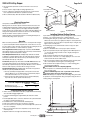
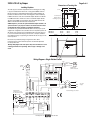
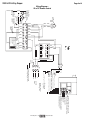
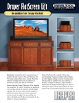
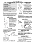
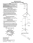
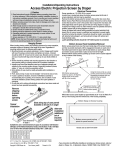
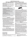
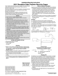
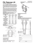
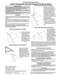
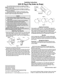
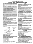
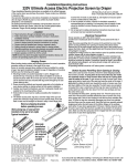
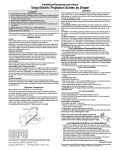
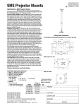
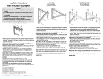
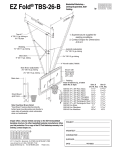
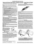
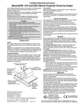
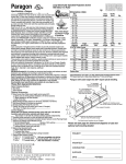
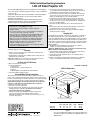
220 Volt Installation/Operating Instructions
LCD Lift Video Projector Lift
These Installation/Operating Instructions are available in the official language
of the country where you purchase the product. Please contact your distributor
to request a copy.
Vous pourriez demander les instructions d’installation et d’opération traduises
dans la langue officielle du pays ou vous achetez le produit. Veuillez
demander à votre distributeur.
Die Gebrauchsanweisung für Installation und Konstruktion sind in der
offiziellen Sprache des Landes, indem Sie das Produkt gekauft haben,
vorhanden. Fragen Sie die jeweilige Verkaufs-Abteilung.
Caution
➀ Read instructions completely before proceeding.
➁ Follow instructions carefully. Installation contrary to instructions
invalidates warranty.
➂ Do not obstruct operation of doors or universal (flat) closure with fingers
or any object. Serious injury or damage could result.
➃ It is not uncommon to overheat the motor during initial installation when
setting limits. The motor is thermally protected and will stop working
temporarily. DO NOT physically pull the unit down when this occurs.
Once it has cooled to a safe temperature, it will begin operating again.
➄ LCD Lift is designed to accommodate ceiling suspended equipment.
Equipment should not be allowed to rest on doors during operation.
➅ Unit must be installed level (use a carpenter’s level).
➆ Perform Pre-Installation Testing Procedures before beginning installation.
➇ Unit operates on 220-240 V AC current.
Note: Unit has been thoroughly inspected and tested at factory and found to be
operating properly prior to shipment.
Planning
➀ Based on screen location and projector specifications, determine proper
position for projector installation.
➁ Confirm that there is adequate space available above the ceiling: 49 cm for
LCD Lift A; 62 cm for LCD Lift B.
NOTE: Add an additional 2 cm of ceiling space if using ceiling closure panel.
➂ Arrange to provide service access to electrical control box.
➄ Use the switch to move the traveling pan up and down. Removal of the
access panel will allow the observation of this movement. The unit will stop
automatically when it reaches the fully up or fully down position.
➅ Cycle the unit in both directions until you are satisfied the unit is operating
properly. If for any reason the unit does not seem to operate properly, call
Draper, Inc. 765/987-7999. Do not proceed with installation.
➆ If the unit has been ordered with the remote control option, again verify
operation of the unit by use of the hand held transmitter. If for any reason
the unit does not seem to operate properly, call Draper, Inc., 765/987-7999.
Do not proceed with installation.
➇ If the unit is operating satisfactorily, remove and discard the temporary
plug.
➈ Disconnect the switch at the terminal board (terminals #1, #3, and #7). Do
not discard this switch. It is to be used as the wall switch.
➉ Replace the cover on the electrical box and proceed with the installation,
referring to instructions supplied.
Hanging Unit
The LCD Lift may be installed in a variety of ways. Typically, it is recessed above
the ceiling and supported by four ½" (12.7 mm) threaded mounting rods. The
bottom of the LCD Lift should be recessed approximately 4 cm above the finished
ceiling. The threaded rods should pass through mounting holes supplied in each
corner and be secured by nuts above and below (see Fig. 1). The unit should then
be guy wired or blocked to prevent swinging. All installations should observe the
following guidelines:
➀ Installer must ensure that all fasteners and supports are of adequate
strength to securely support LCD Lift and projector.
Caution: DO NOT hang from, "ride" or pull down on the unit. This could
create a failure and cause damage and/or injury.
➁ Fastening methods must be suitable for mounting surface, and anchored so
vibrations or abusive pulling will not weaken installation.
➂ Unit should be level, with weight shared more or less equally by all four
threaded mounting rods.
➃ Bottom of unit must be unobstructed after installation. 31 cm minimum
clearance is required below LCD Lift A; 37 cm below LCD Lift B.
As Soon as LCD Lift Arrives:
➀ Open carton and inspect for damage.
➁ Locate the following parts:
A. The unit itself
B. Bomb bay doors or optional ceiling closure
C. Controls
D. Optional SMS Low Profile Mount with Universal Bracket
➂ Follow Pre-Installation Testing Procedure.
Continued on next page
LCD Lift Dimensions
This LCD Lift was extensively tested and in perfect condition when it left our
plant. To make sure that it arrived in the same condition, please use the following
procedure to test the unit prior to installation. Draper does not accept back charges
for labor. Make sure that this unit is operating satisfactorily before installation.
Danger! The traveling pan can exert over 30 kg of force. Do not insert any
body parts or other objects into this unit while power is connected.
➀ Remove the unit from the outer carton.
➁ Remove the cover of the electrical box.
➂ Pre-wire supplied controls and make sure the switch is in the off position
and plug the unit into a 220V AC outlet. Caution: Do not touch any
exposed wires while the unit is plugged in.
➃ Inside the electrical box you will find that a temporary plug has been
connected to the terminal board. Extend this plug from the box.
Replace the electrical box cover so that the cover is held loosely (so as not
to crush the wires) in place.
A
A
Pre-Installation Testing Instructions
C
C
B
For 12.7 mm threaded rod
(supplied by others)
D
14.3 mm dia.
mounting holes
Bomb bay door assembly standard.
Flat ceiling closure panel available.
LCD Lift A
LCD Lift B
A
B
C
D
(cm) (cm) (cm) (cm)
60
45 46
28
73
57 58
41
Travel
(cm)
29
42
Lift
Capacity
30 kgs
30 kgs
Figure 1
Copyright © 2008 Draper Inc.
Form LCDLift220V_Inst08
Printed in U.S.A.
If you encounter difficulties installing or servicing your LCD Lift, call
your dealer or Draper, Inc., Spiceland, Ind., (765) 987-7999; or fax
(765) 987-7142.
Page 2 of 4
220V LCD Lift by Draper
➄ Access should be provided to electrical control box in case service is
required.
➅ Do not use unit to support adjacent ceiling, light fixtures, etc.
➆ Do not complete the ceiling below unit until electrical connections have
been completed and unit has been operated successfully.
➇ We recommend safety cables be attached to LCD Lift for added security.
Threaded rod for
unit suspension
Ball chain for
bomb bay doors
Electrical Connections
Unit operates on 220-240V AC, 50 Hz. current.
Opening electrical control box exposes terminals for field connections. Unit
is shipped with internal wiring complete and control switch(es) boxed. Wire
connecting unit to switch(es) and to power supply should be furnished by
installer. Connections should be made in accordance with wiring diagram, and
wiring should comply with national and local electrical codes. All operating
switches should be “off” before power is connected.
LCD Lift should be operated and checked prior to installing bomb bay doors,
universal (flat) ceiling closure or projector.
Operation
When unit is first operated, be cautious. If doors or closure panel do not begin
to open momentarily when switch is flipped “down”, return switch to “off” and
free doors and/or recheck electrical connections before proceeding. Cycle unit
down and up several times to confirm satisfactory operation.
220 V Single Station Control (CE Approved)—3-position UP-OFF-DOWN
switch permits operation to be stopped at any point. Factory set limit switches
automatically stop lift when fully down or fully up.
220 V Multiple Station Control (Not CE Approved)—Switches are similar
in appearance to Single Station Control. Lift stops when switch is released
and may be restarted in either direction. Factory set limit switches stop lift
automatically when fully up or fully down.
24 V Control (CE Approved)—Three-button UP-STOP-DOWN switches stop
at any point desired, operate in any sequence. Factory set limit switches
automatically stop lift when fully up or fully down. Wireless controls—whether
infrared or radio frequency—interface with low voltage control box.
Key Operated Switching (Not CE Approved)—Two kinds of key-operated
switches are optionally available with this unit.
➀ The key-operated power supply switch controls power to the lift and
switches. When it is “off”, the switches will not operate lift. Key may be
removed from the switch in “on” or “off” position.
➁ A three-position key switch permits the lift to be operated directly by
key. In this case, the lift’s operator must have a key.
Threaded rod to
ceiling closure panel
Universal Closure
Bomb Bay Doors
Figure 2
Installing Optional Ceiling Closure
If your LCD Lift is equipped with an optional ceiling closure system, it can be
used as is, or in conjunction with a piece of existing ceiling tile.
➀ If installing with ceiling tile, you may need to cut tile so that its overall
dimensions are the same as (or slightly less than) the closure panel. Place
tile into trim frame. Lay closure panel on top (back side) of ceiling tile, and
tighten screws to hold in place.
➁ If installing large closure, attach brackets to bottom of projector plate
(see drawing at right).
➂ Attach 5/16" threaded rods to slots in projector plate or brackets.
➃ Run unit “up” until bottom pan stops at highest position. Mark position on
5
/16" rods even with ceiling level and cut rods to length (removing from
pan if convenient).
➄ Run unit “down” until bottom pan stops at “show” position.
➅ Attach closure to lower end of 5/16" rods by slipping into four corner slots
and secure with nuts above and below slots.
➆ Run unit “up” again to highest position. Measure distance by which panel
fails to reach required “closed” height for surrounding ceiling.
➇ Run unit “down” then re-adjust mounting of 5/16" rods in traveling grid to
raise panel required distance.
Caution: Make sure nuts are completely tightened.
➈ Test unit operation to confirm that panel will stop in closed position just
before touching ceiling.
Caution: DO NOT hang from, "ride" or pull down on the unit. This
could create a failure and cause damage and/or injury.
NOTE: Immediately upon completion of the surrounding ceiling, unit should
be operated to confirm that optional ceiling closure panel stops just short of
touching ceiling in closed position.
LCD Lift—Required Space Above Ceiling
Bomb Bay Closure (cm)
Universal (Flat) Ceiling Closure (cm)
LCD Lift A
47
49
LCD Lift B
60
62
Installing Bomb Bay Door Closure
➀ Attach closure to LCD Lift frame with factory supplied hardware. Bomb bay
doors should be hanging straight down.
➁ Lower unit until traveling pan is approximately 10 cm above its lowest
position.
➂ Install supplied ball chain to connectors attached to the eye bolts threaded
into angles on traveling pan (See Fig. 2).
➃ Install ball chain to connectors attached to bomb bay doors.
➄ Raise unit to highest position. Doors should close completely.
➅ If the doors do not close completely, lower unit and adjust the eye bolts until
doors close completely.
➆ Once “closed” position has been accomplished, lock eye bolts into place
with hex jam nuts.
➇ Adjust the LCD Lift to the height of the finished ceiling.
Figure 3
www.draperinc.com
(765) 987-7999
Page 3 of 4
220V LCD Lift by Draper
Dimensions of Traveling Pan
Installing Projector
A
The video projector should be suspended from the traveling pan according
to projector manufacturer’s instructions or using optional SMS Low Profile
Mount, and using recommended standard ceiling mounting hardware (“Z”
brackets are attached to bottom side of traveling pan for easier installation).
B
67 mm
67 mm
C
Z brackets and
adaptor plate for
mounting projector.
If SMS Low Profile is used, remove aluminum adaptor bracket from LCD Lift.
Use SMS Low Profile to mark hole locations on aluminum adaptor bracket,
drill holes, attach SMS Low Profile Mount, then slide adaptor bracket, with
SMS Low Profile Mount attached, back into Z brackets.
NOTE: Draper Inc. provides an optional aluminum adaptor bracket or an
optional mount for your projector. Please consult the instruction sheet
packed with the adaptor bracket for installation information.
The LCD Lift has a grounded 220-240V AC, 50Hz outlet for projector power
supply. Power is supplied to this outlet when unit is in “fully down” position. An
AC current sensor has been factory installed and will not allow the projector
to rise into the LCD Lift until the projector has been cooled by its ventilation
fan(s). When the fan(s) stop operating, the LCD Lift will raise the projector into
its stored position.
A
45 cm
C
35 mm
35 mm
A
46 cm
58 cm
LCD Lift A
LCD Lift B
B
32 cm
45 cm
C
3 mm
5 cm
SMS Low Profile with Universal Bracket
Knockouts are provided for passage of signal and control cables.
Unit and projection system should be operated, checked and adjusted as
necessary at this time.
Warning: Keep fingers and other objects away from automatic doors and
traveling pan when unit is operating. Serious injury or damage could
result.
124 mm
Wiring Diagram—Single Station Control
TB1
5
6
7
Wall Switch
SPDT Center Off
Black
Yellow
Black - Down
Red - Up
White - Neutral
Red
Motor
Yellow/
Green
Red - Up
Black - Common
Yellow - Down
5A
1 2 3 4 5 6 7 8 9 10
Black
Black
White
Black
Black
Black
White
Receptacle Lmt
switch (LS4)
NC
Receptacle
Down Travel
Limit Switch Limit Switch
LS2
NC
LS1 NO
Up Travel
Limit Switch
LS3 NC
AC Current
Sensor
1 2 3 4 5
www.draperinc.com
TB1
1
White
2
NEU
3
GND
L1
Dashed wiring by electrician
8 9 10 11 12 13 14 15 16
White
7
White
Black
Red
6
Red
Red
Red
5
Black
Yellow/
Green
Red
Black
Black
Yellow/
Green
1 2 3 4
Black
TB2
Black
Duplex Outlet
Switched on only in
the fully down position
5A
Black
Yellow
Black
Capacitor
White
1 2 3 4 5 6 7 8 9 10
(765) 987-7999
220 V AC
Supply
Red
White
Black
1 2 3 4 5 6 7 8 9 10
Black
5A
1 2 3 4 5 6 7 8 9 10
AC Current
Sensor
1 2 3 4 5
5A
TB1
1
TB1
5
6
7
Black
2
3
White
Yellow/
Green
Splice
Red
Brown
Yellow
Black
White
L1
NEU
GND
Neut 220V AC
Hot Supply
Wiring for Remote
Mounting of LVC.
220 V AC
Supply
Dashed wiring by electrician
Low voltage wiring by others
Eye Port for IR Eye, RF Receiver or LED
Switch. If more than one of these three is
used with one LVC-III, a splitter is required.
3 Button Wall Switch
DOWN - Black
COM - White
UP - Red
Aux Port for connecting additional
LVC-III modules (up to six totalconnect from Aux to Eye)
(765) 987-7999
www.draperinc.com
Red
White
Black
Motor
Red
Yellow/
Green
TB2
Red
Up Travel
Limit Switch
LS3 NC
Black
Black
Yellow
Yellow
Black
Black
White
White
Duplex Outlet
Switched on only in
the fully down position
Yellow/
Green
Black
Red
Black - Down
Red - Up
White - Neutral
Black
Capacitor
Black
White
Receptacle Lmt
switch (LS4)
NC
Receptacle
Down Travel
Limit Switch Limit Switch
LS2 NC
LS1 NO
Black
Red
Black
Black
Page 4 of 4
220V LCD Lift by Draper
Wiring Diagram—
IR or RF Remote Control
Green-Ground