1
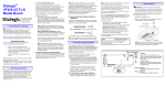
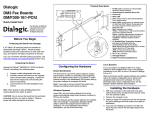
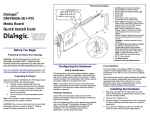
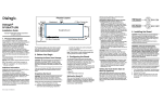
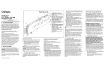
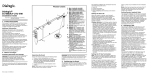
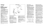
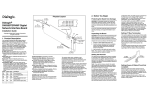
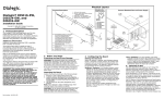
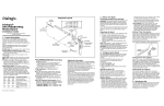
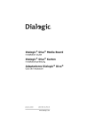
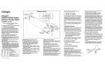
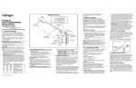
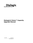
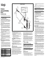
by the edges and avoid touching the board's components.
3. Lay the board on the static-dissipative work surface.
Note: Place board in static-shielding bag when carrying board from station to station.
Physical Layout
CT Bus
Connector
Dialogic®
DNI2410TEPEHMPQ
Board
Installation Guide
L1
L2
L3
L4
G4
P5
(on reverse
side of board)
R3
Y3
G3
R4
Y4
G8
R7
Y7
G7
R8
Y8
G6
R5
Y5
G5
R6
Y6
Yellow Red
Indicated Condition
ON
OFF
OFF
Normal operation
OFF
OFF
ON
Loss of Signal (LOS)
ON
OFF
ON
Red Alarm
ON
ON
OFF
Yellow Alarm/Remote Alarm
Indicator (RAI)
ON
ON
ON
Alarm Indicator Signal (AIS)
Part number: 64-0278-01
Key:
G=Green
L=Loopback (Red)
R=Red
Y=Yellow
1-8=Trunk No.
CAUTION: Do not remove the board from the antistatic packaging until you are ready to install it. Observe proper anti-static precautions at all times.
3. Configuring the Board
Pin
32 s
1
SW1
Power LED
1. Product Description
Green
L5
L6
L7
L8
G2
Alarm/Status
LEDs
Copyright © 2007 Dialogic Corporation. All rights reserved.
The Dialogic® DNI2410TEPEHMPQ board
(“DNI2410TEPEHMPQ” or “board”) is a high-density,
high-performance, network interface board with eight
T1/E1 digital network interfaces in a full-length PCI
Express form factor.
The DNI2410TEPEHMPQ includes the following components, shown in the Physical Layout illustration:
RJ-48C jacks: Four connectors, each of which connects to two T1 or E1 trunks via a splitter cable.
Refer to the Physical Layout illustration for the
trunks supported by each connector. The splitter
cable set (four splitter cables) is provided with the
board.
General Network Interface Alarm LED: When lit
(yellow), indicates that an alarm condition is
present on one or more of the trunks. When unlit,
alarm conditions are cleared.
Reset LED: When lit (red), indicates that the board
is in the reset state. When unlit, the board is no
longer in the reset state.
Power LED: When lit (green), indicates that board
power is good. When unlit, either power has not
been applied to the board, or the board has detected that one or more of the on-board-generated
voltages are not correct.
SW1: Rotary switch used when setting board ID.
Alarm/status LEDs: A set of four LEDs for each
trunk. Refer to the Physical Layout illustration for
LED arrangement.
During power-up, the LEDs indicate Power-On Self
Test (POST) status. After the board is started, the
green, yellow, and red LEDs indicate normal operation or Carrier Failure Alarms (CFAs) for each trunk,
as shown in the following table. The Loopback LED
indicates when the respective trunk is in loopback
mode.
R1
Y1
G1
R2
Y2
Reset LED
General Network
Alarm LED
P10
(on component
side of board)
Trunks 1&5
Trunks 2&6
Trunks 3&7
PCI Express
Connector
Power Budgeting Jumper P10: 3-pin jumper to
set how the board responds to the system power
budgeting function.
■ P10 jumper in pins 2-3: Board adheres to power
budgeting values set by system.
■ P10 jumper in pins 1-2: Board ignores power
budgeting values set by system.
Factory default is P10 jumper in pins 2-3.
CT Bus Connector: H.100 computer telephony bus
connector.
P5: CT Bus termination jumper block. Only the
boards in the end positions of a CT Bus cable
should be terminated. Factory default is unterminated (clip installed over one pin only).
PCI Express connector: Host bus connector. Compatible with x1 or larger PCI Express Link connectors.
Additional Information
Additional information about the DNI2410TEPEHMPQ
is available from a number of sources, such as via its
product data sheet, which is accessible at http://
www.dialogic.com/products/list.asp. The product data
sheet provides a functional description of the
DNI2410TEPEHMPQ, as well as information about its
applications, configurations, features, and technical
specifications. Please note that Dialogic may make
changes to specifications, product descriptions, and
plans at any time, without notice.
RJ-48C Jacks
Trunks 4&8
Refer to the Release Guide and the online Release
Update for your Dialogic software release to verify
that the DNI2410TEPEHMPQ is supported in the release, and for information on any new features or issues that may relate to it.
The Regulatory Notices document that is packed with
each DNI2410TEPEHMPQ contains safety warnings
and national requirements for proper operation of
telecommunications equipment. Please read the document carefully before any handling, installation,
connection or other usage or implementation of the
board.
2. Before You Begin
Protecting the Board from Damage
CAUTION: All computer boards are sensitive to electrostatic discharge. Handle all static-sensitive boards
and components at a static-safe work area, and observe anti-static precautions at all times.
If you are not familiar with ESD safety precautions,
visit http://www.dialogic.com/support/hwinstall to
learn more.
Unpacking the Board
Unpack the board according to the following steps:
1. Prepare a static-safeguarded work area.
2. Carefully remove the board from the shipping carton and anti-static packaging. Handle the board
The DNI2410TEPEHMPQ uses Plug and Play technology to simplify installation. No user configuration is
required for IRQ or memory address.
The DNI2410TEPEHMPQ has the following manually
configurable options:
■ Board ID
■ CT Bus termination
■ Power budgeting (see Choosing a Slot section below)
Setting the Board ID
When the system is started, each Dialogic® board is
assigned a board instance ID number that programs
can use to identify individual boards in a multi-board
system. The setting of SW1 controls the generation of
the instance numbers.
Windows* Systems: In a Windows system, leave
SW1 set to the “0” position (the factory default setting) on all Dialogic boards. This setting causes the
system software to assign instance numbers geographically, based on the bus and slot numbers.
Note that there is no way to know what the instance numbers will be until the system is started
and configured, and the instance number for any
given board is likely to change when there is any
change in the number or arrangement of boards in
the system.
After the hardware and the Dialogic® software are
installed, refer to the configuration manager (DCM)
to retrieve the assigned board instance ID number(s). DCM is a utility that enables you to add new
boards to your system, to start and stop system
service, and to work with board configuration data.
This utility can be accessed from the Start menu in
the Dialogic software program folder. For more information about board identification, see the DCM
online help.
Linux Systems: In a Linux system, you must explicitly specify the board ID numbers by setting SW1
on each board to a different position (0-9 or A-F).
After the hardware and the Dialogic software are
installed, refer to the proper configuration files to
retrieve the assigned board instance ID number(s).
For more information about Linux configuration
files, see the Dialogic software release documentation.
Setting CT Bus Termination
If you are connecting multiple boards via a CT Bus
cable, the bus signal should be terminated on the
boards that are located at the ends of the CT Bus cable. All other boards should be left in their factory default configuration with the CT Bus termination pins
not linked.
CT Bus
Connector
CT Bus
Termination
Pins
4. Choosing a Slot
The DNI2410TEPEHMPQ is a full length x1 form factor
PCI Express board that requires 18W of power. The
following explanation and guidelines are provided for
configuration of the product.
Power Budgeting is a new feature, introduced in the
PCI Express Specification, that provides a mechanism
to enable a system to negotiate power consumption
requirements for add-in devices.
Per PCI Express Card Electromechanical Specification
Revision 1.0a or higher, a x1 add-in card can draw no
more than 10W in a x1 slot unless the board’s required power is successfully negotiated and allocated
by the system (power budgeting). However, implementation of power budgeting by a vendor's system
is not a compliance requirement per the PCI Express
Card Electromechanical Specification Revision 1.0a or
higher. Therefore, some chassis may not support this
feature. Power Budgeting jumper P10 is designed to
ensure proper configuration of the product.
The DNI2410TEPEHMPQ must be installed in a slot
that can be allocated 18W of power.
If Power Budgeting is not implemented by a vendor's
system, the DNI2410TEPEHMPQ must be plugged
into a x4 or higher slot with the P10 jumper in position 1-2 (power budgeting ignored). This is allowed
per PCI Express Card Electromechanical Specification
Revision 1.0a or higher because a x4 or greater slot
must be able to support a minimum of 25W of power.
If Power Budgeting is implemented by a vendor's system, the DNI2410TEPEHMPQ can be plugged into a
x1 slot but the P10 jumper must be in position pins 23 (power budgeting adhered to).
WARNING! Installing the DNI2410TEPEHMPQ
in a x1 slot with the P10 jumper in position 1-2
will void the warranty of the
DNI2410TEPEHMPQ.
If the DNI2410TEPEHMPQ will be connected to one or
more other boards via a CT Bus cable, you should install the boards to minimize unused connectors on
the CT Bus cable (in addition to ensuring that the
power requirements are met):
■ Install boards in adjacent slots whenever possible.
■ If the DNI2410TEPEHMPQ will be connected to one
or more PCI boards, use the PCI Express slot(s) located closest to the PCI slots.
5. Installing the Board
WARNING! Unplug the equipment before performing the procedures described in this section. Failure to disconnect the power before you
open the chassis can result in personal injury.
Ensure that the system is disconnected from its
power source and from all telecommunications
links, networks, or modem lines whenever the
chassis cover is removed. Do not operate the
system with the cover removed.
8. Removing the Board
CAUTION: To avoid possible damage to the board,
remove power from the computer before beginning
installation. Observe proper anti-static precautions at
all times while handling and installing the board.
To install the DNI2410TEPEHMPQ, perform the following steps:
1. Turn off all power to the system and disconnect
the system’s power cords.
2. Remove the computer’s cover.
3. Choose an empty PCI Express expansion slot and
remove that slot’s retaining screw and access
cover plate.
4. Insert the board’s edge connector into the bus
slot, and apply firm pressure to the top edge of
the board until the board is fully seated in the
edge connector.
5. Reinstall the retaining screw.
Remove
Cover
Plate
PCI Express
Slots
Removal of the DNI2410TEPEHMPQ is essentially the
reverse of the installation procedure, as summarized
in Step 1 through Step 7 below:
1. Observe anti-static precautions.
2. Disconnect the telephony cables and splitter cables.
3. Remove the computer’s power cord.
4. Remove the computer’s cover.
5. Disconnect the CT Bus cable (if applicable).
6. Remove and set aside the board’s retaining screw.
7. Remove the board and place it in static-protective
packaging.
Note:
Your CT Bus cable may
have a different number of
connectors (drops).
6. Connecting to External Equipment
Each RJ-48C jack on the DNI2410TEPEHMPQ supports two T1 or E1 digital network interfaces. A splitter cable set consisting of four splitter cables is provided with the board. Connect a splitter cable to each
RJ-48C jack on the rear bracket of the
DNI2410TEPEHMPQ. The following figure illustrates
the pinouts of the four RJ-48C jacks on the
DNI2410TEPEHMPQ.
9. Contacting Technical Support
Dialogic provides technical support for its products
through a network of value added distributors who
are trained to answer technical questions on installing
and configuring Dialogic products. If you are unsure
how to contact your support channel, please call
Dialogic in the United States at 973-967-6600 (9am 5pm EST) and we will assist in obtaining the appropriate support channel. Outside the United States
please refer to http://www.dialogic.com/support/
contact to obtain local contact information.
Dialogic also provides direct support via Dialogic®
Pro™ Services agreements. For more details of direct
support from Dialogic please refer to http://
www.dialogic.com/support/DialogicPro.
Pinout for RJ–48C Jacks (4) on
DNI2410TEPEHMPQ Bracket
1
2
3
4
5
6
7
8
1
2
3
4
5
6
7
8
RCV_RING A
RCV_TIP A
RCV_RING B
XMIT_RING A
XMIT_TIP A
RCV_TIP B
XMIT_RING B
XMIT_TIP B
10.Returning a Product
Note: "A"= lower trunk number and "B"= higher trunk
number for each connector. For example, trunks 1&5,
2&6, 3&7, 4&8.
PCI Express
Board
Computer
Chassis
does support the DNI2410TEPEHMPQ before configuring the system for the newly installed board(s).
Please refer to the Release Update document for your
Dialogic software version for up-to-date information
about support for the DNI2410TEPEHMPQ and any
known issues relating to its use.
CT Bus
Cable
Colored
Stripe
(Pin 1)
To return a board for warranty repair or for any other
returns, please refer to the following: http://
For connections to CSUs or other network termination
equipment, the splitter cable breaks out the two T1/
E1 trunk interfaces on a single RJ-48C connector to
the standard wire pairs of two separate RJ-48C modular connectors. On the Y-adapter end of the splitter
cable, the connector labeled “A” is for the lower trunk
number and the connector labeled “B” is for the
higher trunk number supported by each cable, for example, trunks 1&5, 2&6, 3&7, and 4&8. Each connector has the following pinouts:
www.dialogic.com/support/hwfaults
PCI Slots
6. Repeat Step 3 through Step 5 for any additional
boards you are installing.
7. If applicable, connect the boards together with a
CT Bus cable of the appropriate size (not included). If possible, use a cable assembly that
matches the total number of boards in your system. If the cable has more than one unused connector, install the cable so that all the unused
connectors are at one end of the cable.
8. Replace the computer’s cover.
9. Reconnect the computer’s power cord.
1
RCV_RING
4
XMIT_RING
7
Not used
2
RCV_TIP
5
XMIT_TIP
8
Not used
3
Not used
6
Not used
7. After Installing the Board
The DNI2410TEPEHMPQ requires the use of a Dialogic
software release that specifically supports it.
If this is the first Dialogic board you have installed in
your system, you will need to install an appropriate
version of the Dialogic software and to configure the
software for the specific board(s) you are using. For
instructions, refer to the installation and configuration documentation that accompanies the release.
If you are installing the DNI2410TEPEHMPQ in a system that already has Dialogic software installed, you
should verify that your installed software version supports the board. If it does not support the board, you
will need to obtain and install a Service Update that
Doc. ID: 05-2592-001
To terminate the CT Bus, install a link clip over the
pair of P5 pins indicated in the following figure.
All contents of this document are furnished for informational use only and are subject
to change without notice and do not represent a commitment on the part of Dialogic
Corporation or its subsidiaries (“Dialogic”). Reasonable effort is made to ensure the
accuracy of the information contained in the document. However, Dialogic does not
warrant the accuracy of this information and cannot accept responsibility for errors,
inaccuracies or omissions that may be contained in this document.
INFORMATION IN THIS DOCUMENT IS PROVIDED IN CONNECTION WITH DIALOGIC®
PRODUCTS. NO LICENSE, EXPRESS OR IMPLIED, BY ESTOPPEL OR OTHERWISE, TO
ANY INTELLECTUAL PROPERTY RIGHTS IS GRANTED BY THIS DOCUMENT. EXCEPT AS
PROVIDED IN A SIGNED AGREEMENT BETWEEN YOU AND DIALOGIC, DIALOGIC ASSUMES NO LIABILITY WHATSOEVER, AND DIALOGIC DISCLAIMS ANY EXPRESS OR
IMPLIED WARRANTY, RELATING TO SALE AND/OR USE OF DIALOGIC PRODUCTS INCLUDING LIABILITY OR WARRANTIES RELATING TO FITNESS FOR A PARTICULAR
PURPOSE, MERCHANTABILITY, OR INFRINGEMENT OF ANY INTELLECTUAL PROPERTY
RIGHT OF A THIRD PARTY.
Dialogic products are not intended for use in medical, life saving, life sustaining, critical control or safety systems, or in nuclear facility applications.
It is possible that the use or implementation of any one of the concepts, applications,
or ideas described in this document, in marketing collateral produced by or on web
pages maintained by Dialogic may infringe one or more patents or other intellectual
property rights owned by third parties. Dialogic does not provide any intellectual property licenses with the sale of Dialogic products other than a license to use such product in accordance with intellectual property owned or validly licensed by Dialogic and
no such licenses are provided except pursuant to a signed agreement with Dialogic.
More detailed information about such intellectual property is available from Dialogic’s
legal department at 9800 Cavendish Blvd., Montreal, Quebec, Canada H4M 2V9.
Dialogic encourages all users of its products to procure all necessary intellectual property licenses required to implement any concepts or applications
and does not condone or encourage any intellectual property infringement
and disclaims any responsibility related thereto. These intellectual property
licenses may differ from country to country and it is the responsibility of
those who develop the concepts or applications to be aware of and comply
with different national license requirements.
Dialogic, Diva, Eicon, Eicon Networks, Eiconcard and SIPcontrol, among others, are
either registered trademarks or trademarks of Dialogic. Dialogic's trademarks may be
used publicly only with permission from Dialogic. Such permission may only be
granted by Dialogic’s legal department at 9800 Cavendish Blvd., 5th Floor, Montreal,
Quebec, Canada H4M 2V9. Any authorized use of Dialogic's trademarks will be subject
to full respect of the trademark guidelines published by Dialogic from time to time and
any use of Dialogic’s trademarks requires proper acknowledgement. The names of actual companies and products mentioned herein are the trademarks of their respective
owners.