1
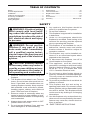
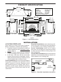
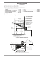
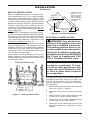
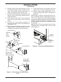
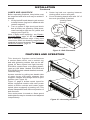
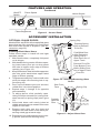
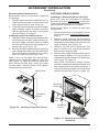
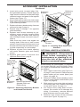
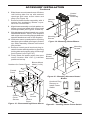
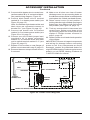
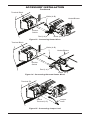
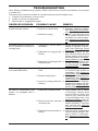
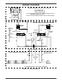
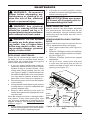
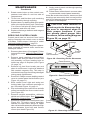
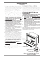
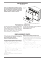
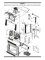
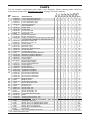
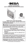
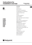
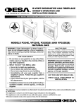
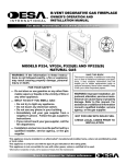
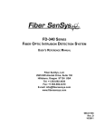
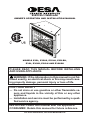
ELECTRIC FIREPLACE OWNER’S OPERATION AND INSTALLATION MANUAL MODELS E32L, E32LB, E32LH, E32LBH, E36L, E36LB, E36LH AND E36LBH PLEASE READ THIS MANUAL BEFORE INSTALLING AND USING APPLIANCE. WARNING: If the information in this manual is not followed exactly, an electrical shock or fire may result causing property damage, personal injury or loss of life. FOR YOUR SAFETY — Do not store or use gasoline or other flammable vapors and liquids in the vicinity of this or any other appliance. — Installation and service must be performed by a qualified service agency. INSTALLER: Leave this manual with the appliance. CONSUMER: Retain this manual for future reference. For more information, visit www.desatech.com Table of Contents Safety................................................................... 2 Product Specification............................................ 3 Installation............................................................ 3 Features and Operation....................................... 7 Accessory Installation........................................... 8 Troubleshooting.................................................. 14 Wiring Diagram................................................... 15 Maintenance....................................................... 16 Technical Service............................................... 23 Replacement Parts............................................. 23 Parts................................................................... 24 Accessories........................................................ 27 Warranty...............................................Back Cover Safety WARNING: Electrical wiring must comply with local building codes and other applicable regulations to reduce the risk of fire, electrical shock and injury to persons. WARNING: Do not use this fireplace if any part of it has been under water. Immediately call a qualified service technician to inspect the fireplace and replace any part of the electrical system. CAUTION: Extreme caution is necessary when any heater is used by or near children or invalids and whenever the heater is left operating and unattended. 1. Read all instructions before using this fireplace. 2. This fireplace is hot when in use. To avoid burns, do not let bare skin touch hot surfaces. If provided, use handles when accessing fireplace controls. Keep combustible materials, such as furniture, pillows, bedding, papers, clothes, and curtains at least 3 feet from front of fireplace. 3. Extreme caution is necessary when any heater is used by or near children or invalids and whenever heater is left operating and unattended. 4. Always place main power switch in OFF position when not in use. 5. Do not operate fireplace if any part has been damaged or is malfunctioning. 6. Any repairs to this fireplace should be done by a qualified service person. 7. Do not use outdoors. 8. This fireplace is approved for installation in bedrooms. 9. Under no circumstances should this fireplace be modified. Parts having to be removed for servicing must be replaced prior to operating this fireplace. 10.This fireplace is not intended for use in bathrooms, laundry areas and similar locations where it would be subject to excessive moisture. 11.This fireplace may not be installed outdoors or in an unenclosed space where exposed to the elements. 12.To disconnect this fireplace, turn off at circuit breaker or fuse panel. 13.This appliance, must be electrically grounded in accordance with local codes and the National Electric Code, ANSI/ NFPA No. 70 or in Canada with CSA C22.1 Canadian Electrical code. 14.Do not insert or allow foreign objects to enter any ventilation or exhaust openings. This may cause an electrical shock, fire or damage to fireplace. 15.To prevent a possible fire do not block air intakes or exhaust. 16.This fireplace has hot and arcing or sparking parts inside. Do not use in areas where gasoline, paint or flammable liquids are used or stored. This fireplace should not be used to dry clothing or for hanging decorations. 17.Use this fireplace only as described. Any other use not recommended by the manufacturer may cause fire, electric shock or injury to persons. 18. SAVE THESE INSTRUCTIONS. www.desatech.com 111076-01F Product Specification E32 = 221/4" E36 = 241/4" E32 = 16 / " E36 = 17 / " 17/8" 5/8" E32 = 363/8" E36 = 43" E32 = 29 / " E36 = 35" 3 8 E32 = 61/2" E36 = 51/4" E32 = 325/8" E36 = 361/4" E32 = 327/8" To Nail 1 2 E36 = 36 / " Location E32 = 183/8" E36 = 21" 3 8 3 4 E32 = 333/8" E36 = 37" E32 = 321/8" E36 = 361/8" E32 = 28 / " E36 = 31 / " E32 = 7" E36 = 8" LEFT SIDE E32 = 8" E36 = 51/4" E32 = 345/8" E36 = 411/4" E32 = 353/8" To Nail E36 = 42" Location E32 = 283/8" E36 = 313/4" TOP E32 = 155/8" E36 = 17" ELECTRICAL SPECIFICATIONS Voltage: 120 VAC, 60 Hz Total Amps: 12.5 Amps Total Watts: 1500 Watts Heater Rating: 1100 Watts Max. Bulb Rating: 100 Watts Use only on 15 amp circuit 1 4 5 8 RIGHT SIDE FRONT Figure 1 - Unit Dimensions Installation LOCATING FIREPLACE Plan where to locate and frame fireplace. Before installation consider the following: 1. Fireplace location must allow for wall and ceiling clearances (see Installation Clearances, page 4). 2. Fireplace screen should not be exposed to direct sunlight from windows or doors. 3. A 15 amp, 120 Volt, 60 Hz circuit with proper ground must be available. A dedicated circuit should be provided to avoid circuit breaker trips or blown fuses. Flush Installations are recommended where living space is limited or at a premium. Since space required to enclose fireplace would be located beyond an outside wall, this installation would require additional planning and construction. Check local codes for any restrictions. Projected Installations can extend any distance into room. A projection may be ideal for a new addition on an existing, finished wall. Corner Installations make use of space that may not normally be used and provides a wider and more efficient viewing angle and heat distribution. Internal Wall Installations provide a discrete option for room separation and can also be an ideal addition to an existing wall. Internal Wall Installation Full Projection Installation Corner Installation Flush Installation Figure 2 - Possible Installation Locations 111076-01F www.desatech.com INSTALLATION Continued INSTALLATION CLEARANCES Minimum clearances to combustible construction are: • Top, Back and Sides of Recessed Cabinet . . . . . . . . . . . . . . . . . . . . . 0" Min. • Floor . . . . . . . . . . . . . . . . . . . . . . . 0" Min. • Drywall to Sides of Front Face . . . 0" Min. • Front . . . . . . . . . . . . . . . . . . . . . . 36" Min. • Framing at Nailing Flanges. . . . . . 0" Min. • Perpendicular Side Wall . . . . . . . 10" Min. • Ceiling to Opening. . . . . . . . . . . . 36" Min. Mantel Clearances For mantel clearances see Figures 3 and 4. Facing Material May Be Noncombustible Wall Treatments or Combustible Wood 12" Ref. 10 1/2" Combustible Wood Mantels and Trims May Extend Above Profile Shown when Maintained within 30° Parameter Shown 4 /2" 1 1 1/2" 30° Framed Material 1 3/4" 16 5/8" Ref. 13 3/4" 10 1/2" Min. Top of Cabinet 9 5/8" Ref. Note: All Mantel Clearances are Measured from Top of Fireplace Opening Figure 3 - Mantel Clearances Edge of Firebox Opening Top View of Fireplace 30° 5" 3" Safe Zone 1 3/4" Max. Minimum 10" from Perpendicular Side Wall Combustible MaterialMust Not Overlap Front Face Figure 4 - Mantel Side Clearances www.desatech.com 111076-01F INSTALLATION Continued BUILT-IN INSTALLATION Built-in installations require a framed enclosure constructed of 2" x 4" or heavier lumber and sized in accordance with Figure 5. This allows unit to slide into opening and be nailed to stud at sides and top nailing flanges. These flanges accept 5/8" drywall or plywood board to finish unit flush to face. Optional trim accessories are available that will extend 1/2" over rough edge of wall opening (see Accessories, page 25). IMPORTANT: If installing a perimeter trim kit, you must install shoulder screws before inserting fireplace into opening. See instructions included with trim kit. If installing a mantel, you must follow clearance instructions (see Installation Clearances, page 4). A hearth extension is suggested for a more pleasing appearance. The fireplace may be raised on a wood or non-combustible platform supporting its entire width and depth and extending in front of the fireplace as long as louvers are not obstructed. Note: When installing fireplace in cold climates against a non-insulated exterior wall, wall must be fully insulated in accordance with local building code. VE32 = 37 /8" VE36 = 42 3/8" VE32 = 26 5/8" VE36 = 29 3/8" VE32 = 52 3/4" VE36 = 58 1/4" 11 5/8" Figure 6 - Corner Dimensions ELECTRICAL INSTALLATION WARNING: Any electrical rewiring of this appliance must be done by a qualified electrician. This wiring must be done in accordance with local codes and/or in the U.S.A. with the current, National Electrical Code ANSI/NFPA No 70 and in Canada with CSA C22.1 Canadian Electric code. This fireplace should be connected to a dedicated 15 Amp, circuit as other appliances may cause the circuit breaker to trip or fuse to blow when fireplace is in operation. Platform/Subflooring VE32 = 32 5/8" VE36 = 36 1/4" VE32 = 15 7/8" VE36 = 17 1/4" VE32 = 34 5/8" VE36 = 41 1/4" Figure 5 - Framing Dimensions 111076-01F These Dimensions Allow for 11 5/8" of Clearance to Side Wall of Fireplace and 10' Clearance to Perpendicular Side Walls 5 A junction box with universal strain adaptor is provided to hard wire unit to a 15 amp, 120 Volt 60 Hz grounded circuit. If necessary, junction box may be relocated to route supply to left side. 1. Remove 2 screws and outer cover on right side (see Figure 7, page 6). 2. Remove inner screw securing junction box. 3. Slide junction box up until mounting tab is lined up to notch in outer cabinet. 4. Swing box out and slip retaining flange out through slot in outer cabinet. 5. Remove 2 screws and outer cover on left side and reattach on right side of outer cabinet. www.desatech.com INSTALLATION Continued 6. Swing junction box with harness to left side while pulling sufficient length of harness out through control panel cover to reach mounting location on left side. 7. Reinsert retaining flange through slot and swing screw mounting tab back through notch as before. 8. Slide junction box down until mounting holes line up and replace inner retaining cover. 9. Pull end of 3 wire Romex supply line through universal strain relief bushing in remaining cover. 10.Strip back outer Romex to about 4” and connect black, white and green wires accordingly using approved connectors. 11.Tuck tailing wires into junction box and replace cover using 2 remaining screws. 12.Tighten down strain adjustment on universal bushing until Romex sheathing is secured. IMPORTANT: Inspect components and wiring for damage before connecting power to unit. If any components are found damaged, contact an authorized dealer for original DESA Heating Products replacement part(s) or call DESA Heating Products at 1-866-872-6040 for referral. IMPORTANT: Prior to operation remove foam shipping brace located under motor mount (see Figure 8). Junction Box Screws and Outer Cover Motor Mount Slot Notch Foam Shipping Brace Retaining Flange Mounting Tab Junction Box Figure 8 - Removing Shipping Brace Screws and Outer Cover from Other Side Cover with Universal Strain Relief Figure 7 - Relocating Junction Box to Left www.desatech.com 111076-01F INSTALLATION Continued Lamps and lava Rock Before operating fireplace, lamp bulbs must be inspected and lava rock may be added if desired. 1. Lift log bed off hearth base to gain access to lamp fixtures (log bed is attached with contact magnets). 2. Turn on power to light circuit and check that all bulbs are operating. Bulb placement front left to right are red, yellow and orange (see Figure 9). Note: If bulbs need replacing, see Replacing Light Bulbs, page 16. Be careful not to tear or damage reflective strips. If they have come loose, ends can be easily reattached or replaced at support brackets. See Replacing Reflective Ribbons, page 21. 3. Center log bed over opening between viewing panel screen and grate. 4. Cover remaining hearth area with 1/4" of lava rock (provided), if desired. Viewing Panel Screen Red Yellow Orange Grate Log Bed Figure 9 - Bulb Placement Features and Operation This electronic fireplace series features a random flame effect, and a realistic log bed with glistening embers that can be adjusted for flame speed and light intensity. E36/32LH models have a circulating heater, rated at 1100 Watts. Models E36/32LB and E36/32LBH include a hand detailed, textured, red-brick lining. Access controls by pulling two handle tabs of upper louver until panel releases from magnetic catches and swings down to open position (see Figure 10). Figure 11, page 8, shows control layout for heater equipped models with main power switch to flame controls and heater power switch (when equipped) to heating unit. This allows independent and efficient operation of both features. Once main power is turned on, flame speed and brightness may be turned on and adjusted independently. Figure 10 - Accessing Controls 111076-01F www.desatech.com FEATURES AND OPERATION ON/OFF Switch MAIN POWER LOW HI- OFF FLAME SPEED Continued Flame Speed Heater Switch HEATER LOW HI- OFF FLAME BRIGHTNESS Flame Brightness Figure 11 - Control Panel Accessory Installation OPTIONAL GLASS DOORS Spring Clip Models E36L and E32L will accept bifold glass doors that are fully operable or a fixed panel door that limits access to fireplace, (see Accessories, page 25). Installing Bifold Glass Doors Follow these steps to install left and right operable panels: 1. With handle down, completely fold panel on its hinges. 2. With handle facing center of firebox opening insert lower pivot pin on door panel into hole in bottom outer edge of firebox opening (see Figure 12). 3. Keep folded door tilted and slide upper two pins into guide track below upper facial edge of firebox opening. 4. Tilt glass assembly fully vertical until outer pivot pin snaps into mounting hole in upper spring clip. 5. Once top and bottom pins are secured, unfold door into closed position. 6. Repeat steps 1 through 5 for opposite door assembly. 7. To adjust doors, slide partially open. Using a Phillips screwdriver, loosen holddown screws on spring clips (see Figure 13). 8. Close both doors until evenly joined at middle and note gap as measured to outer edges of front face. 9. Reopen each door one at a time and retighten the hold-down screw while preserving noted gap at each edge. 10.Repeat process until both doors are evenly joined, spaced and working freely. Depress Spring Clip to Release Pivot Pin Fold Bifold Door After Releasing Spring Clip to Slide Door Out of Upper Track Remove Pivot Pin From Bottom Face While Sliding Door Out of Upper Track Pivot Pin Figure 12 - Installing/Removing Glass Doors Side Front Face Spring Clip Partially Opened Door Figure 13 - Adjust Glass Door www.desatech.com 111076-01F Accessory Installation Continued Removing Bifold Glass Doors Bifold doors may be removed for replacing or cleaning. 1. Partially open each door and press up on upper spring clip with a screw driver until outer top pivot pin is free of the clip. 2. Fully fold frame assembly and slide upper edge towards center of firebox opening until the guide pins are free of the frame rail (see Figure 12, page 8). Installing Series Fixed Glass Doors 1. Hold glass door firmly at both handles and insert top pins into clips located below upper facial edge of firebox opening. Make sure top pins snap securely into holes on spring clips (see Figure 14). 2. Push up on glass against tension of spring clips. Swing lower door into face until lower pins clear bottom rail and set into locating holes on each end (see Figure 14). Note: If pins do not align into spring clips, slightly loosen retaining screws on each clip (see Figure 13, page 8). Reinsert panel into each spring clip and align panel into lower locating holes. Remove panel, finish tighten screws and reinsert panel. Spring Clip OPTIONAL BRICK LINERS Installing or Removing Brick Liner Kits Brick liner kits are available for Models E36/32(L)(H) (see Accessories, page 25). These brick panels may be installed anytime after fireplace installation is complete. Follow these steps to install left and right brick panels: 1. Remove glass doors (if equipped). Follow instructions under Optional Glass Doors, page 8. 2. Remove each retaining screw holding screen rods and pull entire screen and rod assembly out of locating hole on inside top edge of firebox (see Figure 15). 3. Remove log bed from hearth pan and place in a safe area. Log bed is attached with contact magnets only. 4. Remove two screws holding each refractory bracket to firebox. Pull up and lift out of positioning slot at bottom of hearth pan (see Figure 16, page 10). Note: E36L and E36LH models require removal of additional hearth brackets and face panels which are held in place by 2 screws on hearth pan and one screw at top retainer bracket (see Figure 16, page 10). Mounting Holes Locating Hole Screen Rod Figure 14 - Installing Fixed Glass Doors Retaining Screw Figure 15 - Removing Screen/Rod Assembly 111076-01F www.desatech.com Accessory Installation Continued 5. Insert brick panel, beveled edge first, through firebox opening. Tilt and angle top edge into brick retainer until beveled edge contacts imager and panel is flat against firebox (see Figure 17). 6. Align hearth pan bracket over holes near lower edge of brick panel and secure with 2 pan screws provided. 7. Replace refractory bracket using 2 screws removed in step 4, page 9. 8. Repeat steps 5 through 7 for opposite panel assembly. 9. Replace each screen assembly by positioning screen rod into locating holes under top edge of firebox and securing with 2 Phillips screws removed in step 2, page 9. Note: Rods may have to be angled into locating holes at the top of each screen pocket. Once inserted, pull free end of rod forward until it lines up over farthest mounting hole respectively so rods overlap. 10.Replace log bed over hearth opening and center between grate and viewing screen. 11.Replace glass doors if removed. See Optional Glass Doors, page 8. Face Panel (Models E36L and E36LH Only) Refractory Bracket Hearth Pan Bracket (Models E36L and E36LH Only) Figure 16 - Removing Refractory Bracket and Hearth Pan Bracket 10 Refractory Bracket Refractory Retainer Bracket Hearth Pan Bracket Figure 17 - Installing Brick Panels and Brackets OPTIONAL HEATER ACCESSORY WARNING: Disconnect power before attempting any maintenance or cleaning to reduce the risk of fire, electrical shock or personal injury. Blower/heater kit model BHKE is available for models E36/32L and E36/32LB. Either of 2 types of blower/heater assemblies can be installed. 1. Open upper control door (see Figure 10, on page 7) and remove 2 Phillips screws below heater grill on control panel (see Figure 18, page 11). 2. Remove 2 Phillips screws holding control cover to control panel inside firebox (see Figure 14, page 9). 3. Slide control cover to the right and swing out locking tabs from notched openings on top (see Figure 18, page 11). 4. Let control cover hang down off harnesses. Be careful not to damage any wiring. If necessary, unscrew harness strap at blower mount to gain slack. 5. Remove 2 hex screws at rear of blower mount (see Figure 18, page 11). www.desatech.com 111076-01F Accessory Installation Continued 6. Slide blower mount towards rear of firebox until locking tabs line up with notched openings and lower mount down and away (see Figure 18). 7. Remove blower/heater assembly with 4 screws from packaging. Blower is prewired for convenience. 8. Align blower assembly over hole pattern on blower mount and attach with 4 pan head screws provided (see Figures 19 and 20). 9. With discharge pointing towards you, guide assembled blower mount into fireplace and center rear mounting flanges between standoff brackets at rear of the fireplace. 10.Lift blower mount up and position 4 locking tabs through notched openings in firebox top. Slide assembly forward until locked into position. 11.Remove control panel knockout plug located in heater switch position by pressing locking tabs and pushing plug out through front of panel (see Figure 21). 12.Firmly insert red power switch into open mount location with “ON” (I) indicator positioned on top. Harness Strap Blower Mount Mounting Screws Figure 19 - Mounting Heater/Blower Mounting Screws Heater/ Blower Assembly Blower Mount Notch (1 of 4) Notches for Control Cover Control Panel Heater/ Blower Assembly Blower Mount Blower Mount Figure 20 - Mounting Alternate Heater/ Blower Knockout Plug Remove to Install Power Switch Screws Power Switch Control Cover Screws Hex Screws Control Cover Figure 18 - Disassembling Blower Mount 111076-01F Figure 21 - Installing Heater Power Switch www.desatech.com 11 Accessory Installation Continued 13.Connect white heater wire to neutral connection marked 'B' or 'A' on terminal block. See partial wiring diagram, Figure 22. 14.Connect black heater wire to terminal marked 'N-1' on heater power switch (see Figure 23, page 13). Note: On alternate style heaters white and black wires are connected common to terminal 'N-1' (see Figure 24, page 13). 15.Connect red heater wire to terminal marked 'L-4' on heater power switch (see Figure 23 or 24, page 13. 16.Connect one end of black jumper lead, provided in kit, to power connection marked 'D' on terminal block and other end to switch terminal marked 'L-5' (see Figure 25, page 13). 17.Replace 2 hex screws on rear flanges of blower mount removed in step 5, page 10. 18.Remount harness strap to blower mount, if removed. 19.Make sure all wires are clear of heater discharge area, line up mounting holes on front blower mount to holes in control panels and replace the 2 black pan head screws. 20.Raise control cover up and position 2 locking tabs through notched openings in firebox top, then slide to left until locked into position (see Figure 18, page 11). 21.Tuck any excess slack in harnesses into control cover. Swing cover down to line up mounting holes on control panel and replace 2 Phillips screws removed in step 2, page 10. 22.Restore power to unit and check operation of the heater. IMPORTANT: Be sure to inspect components and wiring for damage before connecting power to unit. If any components are found damaged, contact an authorized dealer for original DESA Heating Products replacement parts(s) or call DESA Heating Products at 1-866-872-6040 for referral. GRN WHT BLK WHT CUTOUT BLK D WHT HARNESS C B TERMINAL WHT A WHT - ALTERNATE 4" BLK SUPPLY CONNECTION 4 L N 1 5 L BLK HEATER POWER BLK BLK WIRES TO HEATER CIRCUIT MOTOR RED HEATER COIL RED Figure 22 - Heater Circuit Diagrams 12 www.desatech.com 111076-01F Accessory Installation Continued Terminal Block White (A-B) Heater/Blower Rocker Switch Black (N-1) Red (L-4) Figure 23 - Connecting Heater Wires Terminal Block White (A-B) Heater/Blower Rocker Switch Red (L-4) White (N-1) Figure 24 - Connecting Alternate Heater Wires Terminal (D) Switch Terminal (L-5) Jumper Lead Figure 25 - Connecting Jumper Lead 111076-01F www.desatech.com 13 Troubleshooting Note: Before troubleshooting system, make sure power to circuit from breaker or fuse panel is turned ON. The three most common causes of a malfunctioning electric fireplace are: 1. Tripped circuit breaker or blown fuse. 2. Loose or burned out light bulb. 3. Obstructed or clogged fan blower. OBSERVED PROBLEM POSSIBLE CAUSE REMEDY No operation or indicator light at power/heater switch 1.No power to fireplace 2.Defective switch lamp 1.Check circuit breaker or fuse 2.Replace defective switch. See Servicing Control Panel, page 17 3.Check connections from main power harnesses to terminals on control panel. See Servicing Control Panel, page 17 3.Defective wiring Poor flame motion; flame pattern is sporadic or uneven in viewing area 1.Tangled or loose flame 1.Inspect flame pennants. Unpennants tangle or replace if necessary. See Servicing Flame Pennants, page 19 2.Obstructed or clogged fan 2.Check fan blower for deblower bris. Vacuum areas around blower wheel and remove any obstructions. See Maintaining Motors, page 16 3.Damaged or dislodged fan 3.Remove and inspect fan blower wheel blower housing See Servicing Fan Blower, page 19 Dull flame appearance or inactive ember bed effect 1.Burned out or loose light 1.Inspect light bulbs; tighten bulb or replace light bulbs as necessary. See Replacing Light Bulbs, page 16 2.Broken lamp fixture 2.Remove and replace broken lamp fixture. See Replacing Lamp Fixtures, page 20 3.Loose or missing reflective 3.Inspect reflective ribbons. ribbons Reattach or replace as necessary. See Replacing Reflective Ribbons, page 20 No heat or intermittent heat output. (If equipped with a heater) 1.Obstructed heater blower 14 1.Clear heater fan of debris or blockage; vacuum area around blower intake and remove any obstructions in the discharge area. See Maintaining Motors, page 16 2.Burned out heat element 2.Remove and replace blower or blower fan heater assembly. To access and remove see Optional Heater Accessory, page 10 3.Defective heater switch or 3.Inspect wiring connections wiring from switch to blower. Replace switch if defective. See Servicing Control Panel, page 17 www.desatech.com 111076-01F Wiring Diagram MOTOR CUTOUT HEATER ASSEMBLY - ELECTRICAL DIAGRAM CIRCUIT WHT SPLICE CONNECTION WHT MALE CONNECTION FEMALE CONNECTION RED CAUTION: DISCONNECT FIREPLACE FROM THE ELECTRICAL SUPPLY BEFORE REMOVING THIS COVER CAUTION: USE SUPPLY WIRES SUITABLE FOR 105°C OR EQUIVALENT BLK HEATER COIL RED BLK CONTROL PANEL - ELECTRICAL DIAGRAM HEATER POWER 4 LN 1 BLK 4 LN 1 5 L 5 L SUPPLY CONNECTION WHT - ALTERNATE BLK HARNESS HARNESS C B WHT WHT HARNESS 4" WHT BLK GRN D BLACK 4" BLK 4" BLK BLK GRN MAIN POWER A D C B A TERMINAL TERMINAL WHT BLK BLK FLAME CONTROL FAN CONTROL BLK BLK BLK WHT HARNESS 24" REAR HARNESS TO MOTOR CIRCUIT FRONT HARNESS TO LAMP CIRCUIT WHT GRN BLK WHT BLK GRN WHT BLK RED LAMP YELLOW LAMP ORANGE LAMP BLK BLK FAN MOTOR FLAME PROJECTOR - ELECTRICAL DIAGRAM Figure 26 - Wiring Diagram 111076-01F www.desatech.com 15 Maintenance WARNING: Disconnect power before attempting any maintenance or cleaning to reduce the risk of fire, electrical shock or personal injury. 6. If all bulbs are working properly, replace log bed over center opening between rear screen and front grate. CAUTION: Make sure power is turned off at supply prior to disassembling this unit. WARNING: Any electrical repairs or rewiring of this unit should be carried out by a licensed electrician in accordance with national and local codes. Maintaining Motors WARNING: Do not exceed 60 watts per bulb when replacing bulbs. Use of higher-rated bulbs may result in a fire, causing property damage, personal injury, or loss of life. Removing/Replacing Control Door Replacing Light Bulbs There are (3) colored lamps rated at 120V, 60 Watts, for use in a medium sized socket. These bulbs are located under the log bed and can be replaced as follows: 1. If you are unsure which bulb needs replacement, defective bulbs may be visually located as any of 3 bulbs colored - Red, Yellow and Orange starting from the left (see Figure 9, page 7). Defective bulbs can be replaced individually or for convenience you may want to replace all bulbs at the same time; even if only one is defective. 2. Disconnect power to unit at main breaker or fuse panel. 3. Lift log bed off hearth base to gain access to lamp fixtures. Log bed is attached with contact magnets only. 4. Remove each defective bulb from its socket and replace with appropriate color and size bulb. Note: Be careful not to tear or damage reflective ribbons. If they have come loose, they can be easily reattached or replaced at the support brackets. See Replacing Reflective Ribbons, page 21. 5. Return power to circuit and turn main power switch and lamp power on to check operation of bulbs before replacing log set. 16 Motors used on fan and heater assembly are permanently lubricated and do not require lubrication. Annual cleaning and/or vacuuming around heater and fan unit is recommended. Upper control door may be removed for service or replacement when necessary: 1. Open upper control door (see Figure 10, page 7). 2. Remove 4 Phillips screws from deflector shield. Angle deflector shield out of opening (see Figure 27). 3. Remove 4 Phillips screws from magnet assemblies. 4. Lift up on inner control door and push in each end until pivot pins are free of notches located on each side of access opening (see Figure 27). Deflector Shield Push Door Up and Back Control Door Magnet Assembly Angle Door and Slide Out of Housing. Figure 27 - Removing/Replacing Control Door www.desatech.com 111076-01F MAINTENANCE Continued 5. Rotate control door up into control compartment and slide on end into side of compartment. 6. Tilt out one end first then pull remaining door assembly through opening. 7. Replace door, by starting with door upside down, pins up and facing unit. Follow step 5 in reverse until pins are firmly set back in notches and door will close. 8. Replace discharge deflector and magnet assemblies. Servicing Control Panel Control panel can be serviced from inside unit by removing rear control cover on inside of firebox. Follow steps 2 through 4 under Optional Heater Accessory, page 10. If control assembly needs complete replacement, proceed to remove entire control assembly as follows: 1. Remove glass doors (if equipped). Follow instructions under Optional Glass Doors, page 8. 2. Remove each retaining screw holding screen rods and pull entire screen and rod assembly out from locating hole on inside top edge of fireplace (see Figure 18, page 11). 3. Remove log bed from hearth pan and place in a safe area. Log bed is attached with contact magnets only. This step is included to keep logs from being damaged during panel replacement. 4. Remove 2 Phillips screws holding control cover to control panel inside firebox (see Figure 18, page 11). 5. Slide control cover right and swing out locking tabs from notched openings on top. See detail Figure 18, page 11. 6. Pop out bushings on control cover and slip power harnesses free from control cover (see Figure 28). 7. Remove magnet assemblies, deflector shield and control door. See Removing/ Replacing Control Door, page 16. 8. Remove 4 screws from control panel (see Figure 29). Tilt entire control assembly forward to clear lower flange at upper door rail and slide assembly down through space between front face and firebox mount (see detail Figure 30). 111076-01F 9. Angle control panel out through opening (see Figure 30). 10.Follow these instructions in reverse order to reassemble control panel assembly. Note: Be certain that all wires, harnesses and bushings are returned to their normal position and free of damage before reconnecting supply power to the fireplace. CAUTION: Note location of all wires prior to disconnecting. Be sure to reconnect wires to their proper locations. If you are unsure about proper wire locations, follow wiring diagram Figure 26, on page 15. Bushings Control Cover Power Harnesses Figure 28 - Detaching Power Harnesses Panel Screws MAIN POWER LOW FLAME SPEED LOW FLAME BRIGHTNESS HEATER Figure 29 - Panel Screws Location Control Panel Figure 30 - Removing Control Panel www.desatech.com 17 MAINTENANCE Continued Accessing Imaging Unit Imaging unit can be accessed from inside fireplace for servicing as follows: 1. Remove glass doors (if equipped). See Optional Glass Doors, on page 8. 2. Remove screens, grate, hearth pan brackets and brick liners. See Figure 31 and instructions under Optional Brick Liners, page 9. 3. Remove 4 Phillips screws holding hearth pan to fireplace and 2 screws located at lower frame rail (see Figure 32). 4. Lift rear ends of hearth pan up until front edge clears lower frame rail then slide up on end and angle out of fireplace opening. 5. Remove 4 Phillips screws holding face extensions at top refractory clips (see Figure 32). 6. Remove viewing screen from cabinet face. Viewing screen is attached by magnets (see Figure 33). Note: Do not scratch viewing screen. Place on a nonabrasive surface away from work area. When replacing viewing screen painted side must face inside of cabinet with pattern facing up. Hearth Pan Bracket 7. Remove 4 Phillips screws on base cover and lift cover off cabinet base. See Figure 34, page 19. Note: Only E32 series models have face extensions that require removal to access imaging unit. Model E36 series has inner face panels that also require removal to access imaging unit. Refractory Clip Hearth Pan Face Extensions Figure 32 - Removing Hearth Pan and Face Extensions (Extensions for E32 Series Only) Brick Liner Grate Refractory Brackets Brick Liner Hearth Pan Bracket Viewing Screen Figure 31 - Accessing Imaging Unit 18 Figure 33 - Removing Viewing Screen www.desatech.com 111076-01F MAINTENANCE Continued 5. Lift entire fan assembly off of mounts and tilt out of unit. 6. Remove screws with washers and hex nuts from fan housing. 7. Mount new fan to blower mount in reverse order. 8. Slide blower assembly with spacers over mounting lugs and replace washer and nut at each lug. Do not over tighten. 9. Attach blade connectors to posts on motor mount. Note: Wire connectors for fan motor are non-polarized and may be connected to either terminal for proper operation. Base Cover Figure 34 - Removing Base Cover Servicing Fan Blower To remove fan blower: 1. Follow instructions under Accessing Imaging Unit, page 18. 2. Remove 3 light bulbs from lamp fixtures (see Replacing Light Bulbs, page 16). 3. Disconnect two 1/4" blade connectors at from posts on motor unit. 4. Remove 4 hex nuts and washers located on blower mounts at base of cabinet (see Figure 35). Hex Nut Washer Spacer Servicing Flame Pennants If flame pennants should become tangled or detached reattach or replace. 1. Locate affected flame pennant. Slip hem at base of flame pennant over proper hanger bracket position. See Figure 36, page 20, for proper location. 2. Pull flame cord up to proper hook location, use a slip knot to adjust cord length and attach cord to hook. 3. Tie another knot over slip knot and trim away excess cord. Washer Hex Nut Blower Mount (1 of 4) Screw Fan Assembly Posts for Blade Connectors Figure 35 - Removing Fan Assembly (Shown without Firebox for Clarity) 111076-01F www.desatech.com 19 MAINTENANCE Continued Note: Flame pennant should not be twisted or tangled and should hang slightly loose to allow free movement. If cord is too short or pennant is torn you must obtain a replacement flame assembly (see Replacement Parts, on page 23). Hook 1 1/2" 3 1/2" 7" 8" Flame Cord 4. After connecting and adjusting flame cords, soak each knot with a drop of white wood glue or clear nail polish to prevent unraveling. Flame Pennant Flame Spacer Figure 36 - Locating Flame Pennants Replacing Lamp Fixtures Lamp fixtures may be replaced as follows: 1. Turn off all power to fireplace at circuit breaker or fuse. 2. Locate any of 3 defective lamp fixtures and trace wiring to crimp connectors in harness and disconnect. 3. Remove 2 crimp connectors in harness and disconnect white and black wires on defective fixture. See Wiring Diagram, Figure 26 on page 15, for proper locations. 4. Remove 2 Phillips screws at base of defective fixture (see Figure 37, page 21). 20 5. Remove old fixture and mount new fixture with 2 Phillips screws removed prior. 6. Twist bare ends of white and black wires to corresponding wires in main harness and secure them with 2 crimp connectors provided. Note: There should be no exposed bare wire at any connection. Wiring should be secured with wire ties, as short as possible, and kept away from fan blades. If additional parts are required, see Replacement Parts, on page 23. www.desatech.com 111076-01F MAINTENANCE Continued 7. Replace each light bulb with proper color, (see Replacing Light Bulbs, page 16). 8. Restore power and check lamp circuit operation before reassembling imaging unit. 9. Reassemble imager. See Accessing Imaging Unit, page 18. Make sure power is turned off at supply prior to disassembling this unit. IMPORTANT: Be sure to inspect components and wiring for damage before connecting power to unit. If any components are found damaged, contact an authorized dealer for original DESA Heating Products replacement part(s) or call DESA Heating Products at 1-866-872-6040 for referral. Replacing Reflective Ribbons If reflective ribbons become damaged or loose they may be replaced as follows: 1. Turn off all power to fireplace at circuit breaker or fuse. 2. Locate defective ribbon; there are 3 strips mounted on rear cabinet and 3 mounted in base (see Figure 37). Upper Hanger Bracket Screws and Washers Hanger Screws Reflective Ribbon Bottom Hanger Bracket Screws Lamp Fixture Crimp Connectors Ribbon Support Bracket Reflective Ribbon Base Cover Cellophane Tape Figure 37 - Replacing Fixtures (Shown without FIrebox for Clarity) 111076-01F www.desatech.com 21 MAINTENANCE Continued 3. If upper back cabinet ribbons need replacing, remove 4 Phillips screws holding corresponding bottom and top hanger brackets (see Figure 37, page 21). 4. Remove any loose or damaged ribbon material. 5. Cut an 18” strip of reflective ribbon and position top end about an inch above top bracket position (see Figure 37, page 21). Note: Ribbon material should be applied with reflective side up, should not be twisted or tangled, and should hang slightly loose to allow free movement. If additional parts are required, see Replacement Parts, page 23. 6. Replace top hanger bracket using 2 Phillips screws removed in step 2 and tighten until reflective ribbon is held in place. 7. Replace bottom hanger bracket using 2 remaining Phillips screws to secure lower end of reflective ribbon. 8. If replacing reflective ribbons located in base, remove screws and washers at damaged ends of ribbon. 9. Cut a 9" long strip of ribbon and apply across each ribbon support bracket with shiny side facing up (see Figure 37, page 21). 10.Secure ribbon to brackets by replacing each washer at end of the ribbon and rethreading screws through the ribbon into each hole located on support brackets. 11.If replacing top reflective ribbons on base cover, cut a 3" section of ribbon and split down the middle. With shiny side up, attach with cellophane tape into rear edge of base cover opening (see Figure 37, page 21). 12.Readjust flame pennants (if removed). See Servicing Flame Pennants, page 19. 13.Reassemble imager. See Accessing Imaging Unit, page 18. 14.Center log bed over opening between viewing panel screen and grate. 15.Cover remaining hearth area with 1/4" of lava rock (provided), if desired. Cleaning Viewing Screen Clean viewing screen with an alcohol based, nonabrasive, residue free cleaner (premoistened hand wipes are ideal). Do not use glass cleaners with ammonium, abrasive scrubs or degreaser solvents of any kind. Accessing Imaging Unit For Replacement The imaging unit can be removed from inside the firebox for servicing or replacement: 1. Follow steps under Accessing Imaging Unit, on page 18. 2. Remove 4 hex screws on lower louver panel and detach louver assembly from front face (see Figure 38). 3. Rotate top edge of lower frame rail inward and lift upward until locking tabs detach from front face (see Figure 38). 4. Slide entire imaging unit forward and lift out through front opening (see Figure 39, page 23). Note: An additional 3 feet of harness is tucked behind imager to permit removal without disconnecting any control wiring. Lower Frame Rail Lower Panel Lower Frame Rail Locking Tab Figure 38 - Removing Lower Louver Panel and Frame Rail 22 www.desatech.com 111076-01F MAINTENANCE Continued Note: If full replacement of imager is necessary, wiring harnesses must be disconnected and new harnesses reconnected at control panel. For proper connection, follow wiring diagram shown in Figure 26, page 15. Imaging Unit Figure 39 - Removing Imaging Unit Technical Service You may have further questions about installation, operation or troubleshooting. If so, contact DESA Heating Products’ Technical Service Department at 1-866-672-6040. When calling, please have your model and serial numbers of your firebox ready. You can also visit DESA Heating Products’ technical services web site at www.desatech.com. Replacement Parts Note: Use only original replacement parts. This will protect your warranty coverage for parts replaced under warranty. Parts Under Warranty Contact authorized dealers of this product. If they can’t supply original replacement part(s), call DESA Heating Products’ Technical Service Department at 1-866-672-6040. When calling DESA Heating Products, have ready • your name • your address • model and serial numbers of your firebox • how firebox was malfunctioning • type of gas used (propane/LP or natural gas) • purchase date Usually, we will ask you to return the part to the factory. 111076-01F Parts Not Under Warranty Contact authorized dealers of this product. If they can’t supply original replacement part(s), call DESA Heating Products at 1-866-672-6040 for referral information. When calling DESA Heating Products, have ready • model number of your firebox • the replacement part number Note: The firebox identification label (including model number, serial number, clearances, etc.) is located on the right front edge of the firebox. www.desatech.com 23 Parts Models E32L, E32LB, E32LH, E32LBH, E36L, E36LB, E36LH and E36LBH 24 26 23 27 25 28 29 30 31 32 27 28 17 30 18 15 17 13 34 22 21 32 33 34 12 20 19 11 17 14 10 15 16 20 10 9 36 14 2 12 7 8 6 11 37 8 3 3 5 1 4 35 24 www.desatech.com 111076-01F PARTS 1 Louver Assembly (Bottom) Louver Assembly (Bottom) • 2 Louver Assembly )Top) Louver Assembly )Top) • 3 Refractory Bracket • 4 Face Weldment • 5 Hearth Pan Hearth Pan • 6 Lower Face Rail Lower Face Rail • 7 Door Stop • 8 Hearth Pan Bracket Hearth Pan Bracket • 9 Imager, Fireplace Insert (Except for bulbs, parts • not individually available for field replacement.) 10 112137-01 Refractory Panel, 36" 113662-01 Refractory Panel, 32" 11 120160-01 Hearth Panel 12 112414-01 Extension Face 112414-02 Extension Face • 13 119084-01 Refractory Standoff Panel 14 110445-01 Hearth Bracket • 15 110973-01 Junction Box Cover • 16 14123 Universal Strain Relief Bushing • 17 112075-01 Refractory Retainer Bracket • 112075-02 Refractory Retainer Bracket 18 119089-01 Panel Valance • 19 110974-01 Junction Box • 20 M11143-01 Strain Relief Bushing • 21 ** Firebox Outer Wrap • 22 111064-01 Heater Standoff Bracket • 23 110439-01 Heater Mount 110439-02 Heater Mount • 24 111060-01 Heater Assembly 25 107941-02 Top/Bottom Fireplace • 107941-03 Top/Bottom Fireplace 26 112302-01 Control Panel Assembly 112302-02 Control Panel Assembly 112302-04 Control Panel Assembly 112302-05 Control Panel Assembly • 27 112783-01 Magnet Bracket • 28 17223 Magnet Catch • 29 112099-01 Heat Deflector Shield • 30 11439 Electrical Bushing 7/8" • 31 112305-01 Control Cover • 32 11418 Push-On nut • 33 106691-01 Screen Rod, 36" 108701-01 Screen Rod, 32" • 34 12105 Screen Assembly, 36" 108440-01 Screen Assembly, 32" • 35 112748-01 Log Ember Bed Assembly • 36 112735-01 Grate • 37 112743-01 Viewing Panel Screen, 36" 117755-01 Viewing Panel Screen, 32" • PARTS AVAILABLE - NOT SHOWN 11198 Screw #8 x 3.8 Hex • 11166 Screw, #10 x 1/2 Phillips Black Oxide • 11164 Screw, #10 x 1/2 Phillips Black Oxide • 11105 Screw, #10 x 1/2 Hex Zinc • 11102 Screw, #8 x 3/8 Phillips Zinc • 25487 Lava Rock • 114266-01 M4 - 8mm Phillips Pan Screw • ** Not a field replaceable part. 111076-01F www.desatech.com • • • • • • • • • • • • • • • • • • • • • • • • • • • • • • • • • • • • • • • • • • • • • • • • • • • • • • • • • • • • • • • • • • • • • • • • • • • • • • • • • • • • • • • • • • • • • • • • • • • • • • • • • • • • • • • • • • • • • • • • • • • • • • • • • • • • • • • • • • • • • • • • • • • • • • • • • • • • • • • • • • • • • • • • • • • • • • LBH LBH • • • • • • • • • • • • • • • • • • • • • • • E36 LH • E32 LH • • • • • • • • • • • • • • E36 LB • E32 LB • E36 L • E32 DESCRIPTION 111065-02 111062-04 111065-01 111065-03 110870-01 ** 112078-01 112078-02 112076-01 112076-02 20088 112138-01 112138-02 112288-02 E36 E32 KEY NO. PART NO. L This list contains replaceable parts used in your fireplace. When ordering parts, follow the instructions listed under Replacement Parts on page 23 of this manual. • • • • • • • • • • • • • • • • • • • • • • • • • • • • • • • • • • • • • • • • • • • • • • • • • • • • • • • • • • • • • • • • • • • • • • • • • • • • • • • • • QTY. 1 1 1 1 2 1 1 1 1 1 1 2 2 1 2 2 2 2 2 2 4 2 1 2 2 1 1 1 1 1 1 1 1 2 2 1 1 1 1 2 2 1 2 1 2 2 2 2 2 1 1 1 1 4 12 30 36 5 1 40 25 Parts Control Panel for Models E32L, E32LB, E32LH, E32LBH, E36L, E36LB, E36LH and E36LBH This list contains replaceable parts used in your fireplace. When ordering parts, follow the instructions listed under Replacement Parts on page 23 of this manual. 8 11 10 1 13 8/9 4 6 13 3 7 2 12 14 2 3 4 5 6 7 8 9 10 11 12 13 14 DESCRIPTION E32 KEY NO. PART NO. /36L (B) E32 /36L (B)( H) 14 1 14 5 111066-03 111066-01 111067-02 111059-01 111059-02 111059-03 111058-01 110799-01 108394-01 108394-01 113042-01 103651-01 103650-01 103646-01 099125-13 11102 Control Panel Decal Control Panel Decal Control Circuit Harness 4" Black Wire Harness 4" White Wire Harness 4" Green Wire Harness Flame Control Panel Control ON/OFF Switch ON/OFF Switch Hole Plug Lock Nut Control Knob Power Wire Harness Terminal Block #8 - 32 x 3/8" Phillips Screw • 114275-01 111066-01 111066-03 112469-01 112469-02 112469-03 4" Wire Tie Control Panel Decal Control Panel Decal Lamp Bulb (Red) Lamp Bulb (Yellow) Lamp Bulb (Orange) • • PARTS AVAILABLE - NOT SHOWN • • • • • • • • • • • • • • • • QTY. • • • • • • • • • • • • • • • • • • 1 1 1 1 1 1 2 1 1 2 1 2 2 1 2 5 14 1 1 1 1 1 ** Not a field replaceable part. 26 www.desatech.com 111076-01F Accessories Purchase these firebox accessories from your local dealer. If they can not supply these accessories, call DESA Heating Products’ Sales Department at 1-866-672-6040 for information. You can also write to the address listed on the back page of this manual. PERIMETER TRIM KITS PT32 - 32" Black PT32B - 32" Brushed Brass PT32PB - 32" Polished Brass PT32P - 32" Platinum PT36 - 36" Black PT36B - 36" Brushed Brass PT36PB - 36" Polished Brass PT36P - 36" Platinum BIFOLD GLASS DOOR KITS BD32 - 32" Black BD32B - 32" Brushed Brass BD32PB 32" Polished Brass BD32P 32" Platinum BD36 - 36" Black BD36B - 36" Brushed Brass BD36PB - 36" Polished Brass BD36P - 36" Platinum 111076-01F FIXED GLASS DOOR KITS FD32 - 32" Black FD32B - 32" Brushed Brass FD32PB - 32" Polished Brass FD32P - 32" Platinum FD36 - 36" Black FD36B - 36" Brushed Brass FD36PB - 36" Polished Brass FD36P - 36" Platinum Textured Brick REFRACTORY LINER KITS BL32E - 32" Red BL32EW - 32" White BL36E - 36" Red BL36EW - 36" White ELECTRIC BLOWER/HEATER KIT BHKE - 1100 Watt Electric Heater Kit www.desatech.com 27 Warranty KEEP THIS WARRANTY Model ____________________________________ Serial No. _________________________________ Date Purchased ____________________________ Always specify model and serial numbers when communicating with the factory. The only warranty applicable is our standard written warranty. We make no other warranty, expressed or implied. LIMITED 1 YEAR WARRANTY DESA Heating, LLC warrants this product to be free from defects for one (1) year from the date of first purchase, provided that the product has been properly installed, operated and maintained in accordance with all applicable instructions. To make a claim under this warranty the Bill of Sale or cancelled check must be presented. This warranty is extended only to the original retail purchaser. This warranty covers the cost of part(s) required to restore this heater to proper operating condition and an allowance for labor when provided by a DESA Heating, LLC Authorized Service Center. Warranty part(s) MUST be obtained through authorized dealers of this product and/or DESA Heating, LLC who will provide original factory replacement parts. Failure to use original factory replacement parts voids this warranty. The product MUST be installed by a qualified installer in accordance with all local codes and instructions furnished with the unit. This warranty does not apply to parts that are not in original condition because of normal wear and tear or parts that fail or become damaged as a result of misuse, accidents, lack of proper maintenance or defects caused by improper installation. Travel, diagnostic cost, labor, transportation and any and all such other costs related to repairing a defective product will be the responsibility of the owner. TO THE FULL EXTENT ALLOWED BY THE LAW OF THE JURISDICTION THAT GOVERNS THE SALE OF THE PRODUCT; THIS EXPRESS WARRANTY EXCLUDES ANY AND ALL OTHER EXPRESSED WARRANTIES AND LIMITS THE DURATION OF ANY AND ALL IMPLIED WARRANTIES, INCLUDING WARRANTIES OF MERCHANTABILITY AND FITNESS FOR A PARTICULAR PURPOSE TO ONE (1) YEAR FROM THE DATE OF FIRST PURCHASE; AND DESA Heating, LLC’S LIABILITY IS HEREBY LIMITED TO THE PURCHASE PRICE OF THE PRODUCT AND DESA Heating, LLC SHALL NOT BE LIABLE FOR ANY OTHER DAMAGES WHATSOEVER INCLUDING INDIRECT, INCIDENTAL OR CONSEQUENTIAL DAMAGES. Some states do not allow a limitation on how long an implied warranty lasts or an exclusion or limitation of incidental or consequential damages, so the above limitation on implied warranties or exclusion or limitation on damages may not apply to you. This warranty gives you specific legal rights and you may also have other rights that vary from state to state. For information about this warranty write: 2701 Industrial Drive P.O. Box 90004 Bowling Green, KY 42102-9004 www.desatech.com 1-866-672-6040 111076.01 NOT A UPC 111076-01 Rev. F 05/07