1
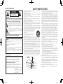
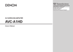
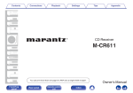
 Graphical User Interface
Use this manual in combination with the
operating guide displayed on the GUI screen.
GUI Menu Operation (vpage 15)
GUI Menu Map (vpage 16)
Language (vpage 21)
VIDEO PROCESSOR
DVP-602CI
Owner’s Manual
DVP602CI_ENG_6th.indd
1
2008/03/26
16:37:05
SAFETY INSTRUCTIONS
nSAFETY PRECAUTIONS
CAUTION
RISK OF ELECTRIC SHOCK
DO NOT OPEN
CAUTION:
TO REDUCE THE RISK OF ELECTRIC SHOCK, DO NOT REMOVE
COVER (OR BACK). NO USER-SERVICEABLE PARTS INSIDE.
REFER SERVICING TO QUALIFIED SERVICE PERSONNEL.
The lightning flash with arrowhead symbol, within an equilateral
triangle, is intended to alert the user to the presence of
uninsulated “dangerous voltage” within the product’s enclosure
that may be of sufficient magnitude to constitute a risk of electric
shock to persons.
The exclamation point within an equilateral triangle is intended
to alert the user to the presence of important operating
and maintenance (servicing) instructions in the literature
accompanying the appliance.
WARNING:
TO REDUCE THE RISK OF FIRE OR ELECTRIC SHOCK, DO NOT
EXPOSE THIS APPLIANCE TO RAIN OR MOISTURE.
CAUTION:
To completely disconnect this product from the mains, disconnect the plug
from the wall socket outlet.
The mains plug is used to completely interrupt the power supply to the unit
and must be within easy access by the user.
VORSICHT:
Um dieses Gerät vollständig von der Stromversorgung abzutrennen, ziehen
Sie bitte den Stecker aus der Wandsteckdose.
Der Netzstecker wird verwendet, um die Stromversorgung zum Gerät völlig
zu unterbrechen; er muss für den Benutzer gut und einfach zu erreichen
sein.
For European model
• DECLARATION OF CONFORMITY
We declare under our sole responsibility that this product, to which this
declaration relates, is in conformity with the following standards:
EN60065, EN55013, EN55020, EN61000-3-2 and EN61000-3-3.
Following the provisions of 2006/95/EC and 2004/108/EC Directive.
1. Read Instructions – All the safety and operating instructions should be read
before the product is operated.
2. Retain Instructions – The safety and operating instructions should be
retained for future reference.
3. Heed Warnings – All warnings on the product and in the operating
instructions should be adhered to.
4. Follow Instructions – All operating and use instructions should be
followed.
5. Cleaning – Unplug this product from the wall outlet before cleaning. Do not
use liquid cleaners or aerosol cleaners.
6. Attachments – Do not use attachments not recommended by the product
manufacturer as they may cause hazards.
7. Water and Moisture – Do not use this product near water – for example,
near a bath tub, wash bowl, kitchen sink, or laundry tub; in a wet basement;
or near a swimming pool; and the like.
8. Accessories – Do not place this product on an unstable cart, stand, tripod,
bracket, or table. The product may fall, causing serious injury to a child
or adult, and serious damage to the product. Use only with a cart, stand,
tripod, bracket, or table recommended by the manufacturer, or sold with
the product. Any mounting of the product should
follow the manufacturer’s instructions, and should
use a mounting accessory recommended by the
manufacturer.
9. A product and cart combination should be moved
with care. Quick stops, excessive force, and
uneven surfaces may cause the product and cart
combination to overturn.
10. Ventilation – Slots and openings in the cabinet are provided for ventilation
and to ensure reliable operation of the product and to protect it from
overheating, and these openings must not be blocked or covered. The
openings should never be blocked by placing the product on a bed, sofa,
rug, or other similar surface. This product should not be placed in a built-in
installation such as a bookcase or rack unless proper ventilation is provided
or the manufacturer’s instructions have been adhered to.
11. Power Sources – This product should be operated only from the type of
power source indicated on the marking label. If you are not sure of the type
of power supply to your home, consult your product dealer or local power
company. For products intended to operate from battery power, or other
sources, refer to the operating instructions.
12. Grounding or Polarization – This product may be equipped with a polarized
alternating-current line plug (a plug having one blade wider than the other).
This plug will fit into the power outlet only one way. This is a safety feature.
If you are unable to insert the plug fully into the outlet, try reversing the
plug. If the plug should still fail to fit, contact your electrician to replace your
obsolete outlet. Do not defeat the safety purpose of the polarized plug.
FIGURE A
EXAMPLE OF ANTENNA GROUNDING
AS PER NATIONAL
ELECTRICAL CODE
(306/%
$-".1
"/5&//"
%*4$)"3(&6/*5
/&$4&$5*0/
• ÜBEREINSTIMMUNGSERKLÄRUNG
Wir erklären unter unserer Verantwortung, daß dieses Produkt, auf das
sich diese Erklärung bezieht, den folgenden Standards entspricht:
EN60065, EN55013, EN55020, EN61000-3-2 und EN61000-3-3.
Entspricht den Verordnungen der Direktive 2006/95/EC und 2004/108/EC.
DENON EUROPE
Division of D&M Germany GmbH
An der Landwehr 19, Nettetal,
D-41334 Germany
"/5&//"
-&"%*/
8*3&
&-&$53*$
4&37*$&
&26*1.&/5
(306/%*/($0/%6$5034
/&$4&$5*0/
(306/%$-".14
13. Power-Cord Protection – Power-supply cords should be routed so that they
are not likely to be walked on or pinched by items placed upon or against
them, paying particular attention to cords at plugs, convenience receptacles,
and the point where they exit from the product.
15. Outdoor Antenna Grounding – If an outside antenna or cable system is
connected to the product, be sure the antenna or cable system is grounded
so as to provide some protection against voltage surges and built-up static
charges. Article 810 of the National Electrical Code, ANSI/NFPA 70, provides
information with regard to proper grounding of the mast and supporting
structure, grounding of the lead-in wire to an antenna discharge unit, size
of grounding conductors, location of antenna-discharge unit, connection to
grounding electrodes, and requirements for the grounding electrode. See
Figure A.
16. Lightning – For added protection for this product during a lightning storm,
or when it is left unattended and unused for long periods of time, unplug it
from the wall outlet and disconnect the antenna or cable system. This will
prevent damage to the product due to lightning and power-line surges.
17. Power Lines – An outside antenna system should not be located in the
vicinity of overhead power lines or other electric light or power circuits, or
where it can fall into such power lines or circuits. When installing an outside
antenna system, extreme care should be taken to keep from touching such
power lines or circuits as contact with them might be fatal.
18. Overloading – Do not overload wall outlets, extension cords, or integral
convenience receptacles as this can result in a risk of fire or electric shock.
19. Object and Liquid Entry – Never push objects of any kind into this product
through openings as they may touch dangerous voltage points or short-out
parts that could result in a fire or electric shock. Never spill liquid of any kind
on the product.
20. Servicing – Do not attempt to service this product yourself as opening or
removing covers may expose you to dangerous voltage or other hazards.
Refer all servicing to qualified service personnel.
21. Damage Requiring Service – Unplug this product from the wall outlet
and refer servicing to qualified service personnel under the following
conditions:
a)When the power-supply cord or plug is damaged,
b)If liquid has been spilled, or objects have fallen into the product,
c) If the product has been exposed to rain or water,
d)If the product does not operate normally by following the operating
instructions. Adjust only those controls that are covered by the operating
instructions as an improper adjustment of other controls may result in
damage and will often require extensive work by a qualified technician to
restore the product to its normal operation,
e)If the product has been dropped or damaged in any way, and
f)When the product exhibits a distinct change in performance – this
indicates a need for service.
22. Replacement Parts – When replacement parts are required, be sure the
service technician has used replacement parts specified by the manufacturer
or have the same characteristics as the original part. Unauthorized
substitutions may result in fire, electric shock, or other hazards.
23. Safety Check – Upon completion of any service or repairs to this product,
ask the service technician to perform safety checks to determine that the
product is in proper operating condition.
24. Wall or Ceiling Mounting – The product should be mounted to a wall or
ceiling only as recommended by the manufacturer.
25.Heat – The product should be situated away from heat sources such as
radiators, heat registers, stoves, or other products (including amplifiers) that
produce heat.
108&34&37*$&(306/%*/(
&-&$530%&4:45&.
/&$/"5*0/"-&-&$53*$"-$0%& /&$"351"35)
I
DVP602CI_ENG_6th.indd
2
2008/03/26
16:37:05
FCC INFORMATION (For US customers)
nNOTE ON USE / HINWEISE ZUM GEBRAUCH
1. COMPLIANCE INFORMATION
Product Name: VIDEO PROCESSOR
Model Number: DVP-602CI
This product complies with Part 15 of the FCC Rules. Operation is subject to the following two conditions: (1) this
product may not cause harmful interference, and (2) this product must accept any interference received, including
interference that may cause undesired operation.
Denon Electronics (USA), LLC
(a D & M Holdings Company)
100 Corporate Drive
Mahwah, NJ 07430-2041
Tel. (800) 497-8921
2. IMPORTANT NOTICE: DO NOT MODIFY THIS PRODUCT
This product, when installed as indicated in the instructions contained in this manual, meets FCC requirements.
Modification not expressly approved by DENON may void your authority, granted by the FCC, to use the product.
3. NOTE
This product has been tested and found to comply with the limits for a Class B digital device, pursuant to Part 15
of the FCC Rules. These limits are designed to provide reasonable protection against harmful interference in a
residential installation.
This product generates, uses and can radiate radio frequency energy and, if not installed and used in accordance
with the instructions, may cause harmful interference to radio communications. However, there is no guarantee
that interference will not occur in a particular installation. If this product does cause harmful interference to radio or
television reception, which can be determined by turning the product OFF and ON, the user is encouraged to try to
correct the interference by one or more of the following measures:
•Reorient or relocate the receiving antenna.
•Increase the separation between the equipment and receiver.
•Connect the product into an outlet on a circuit different from that to which the receiver is connected.
•Consult the local retailer authorized to distribute this type of product or an experienced radio/TV technician for
help.
This Class B digital apparatus complies with Canadian ICES-003.
Cet appareil numérique de la classe B est conforme à la norme NMB-003 du Canada.
A NOTE ABOUT RECYCLING:
This product’s packaging materials are recyclable and can be reused. Please dispose of any materials
in accordance with the local recycling regulations.
When discarding the unit, comply with local rules or regulations.
Batteries should never be thrown away or incinerated but disposed of in accordance with the local
regulations concerning battery disposal.
This product and the supplied accessories, excluding the batteries, constitute the applicable product
according to the WEEE directive.
HINWEIS ZUM RECYCLING:
Das Verpackungsmaterial dieses Produktes ist zum Recyceln geeignet und kann wieder verwendet werden. Bitte
entsorgen Sie alle Materialien entsprechend der örtlichen Recycling-Vorschriften.
Beachten Sie bei der Entsorgung des Gerätes die örtlichen Vorschriften und Bestimmungen.
Die Batterien dürfen nicht in den Hausmüll geworfen oder verbrannt werden; bitte entsorgen Sie die Batterien gemäß
der örtlichen Vorschriften.
Dieses Produkt und das im Lieferumfang enthaltene Zubehör (mit Ausnahme der Batterien!) entsprechen der WEEEDirektive.
• Avoid high temperatures.
Allow for sufficient heat dispersion when
installed in a rack.
• Vermeiden Sie hohe Temperaturen.
Beachten Sie, dass eine ausreichende
Belüftung gewährleistet wird, wenn das
Gerät auf ein Regal gestellt wird.
• Do not let foreign objects into the unit.
• Keep the unit free from moisture, water, • Lassen Sie keine fremden Gegenstände in
and dust.
das Gerät kommen.
• Halten Sie das Gerät von Feuchtigkeit,
Wasser und Staub fern.
• Do not let insecticides, benzene, and
thinner come in contact with the unit.
• Unplug the power cord when not using the
• Lassen Sie das Gerät nicht mit Insektiziden,
unit for long periods of time.
Benzin oder Verdünnungsmitteln in
• Wenn das Gerät längere Zeit nicht
Berührung kommen.
verwendet werden soll, trennen Sie das
Netzkabel vom Netzstecker.
• Handle the power cord carefully.
Hold the plug when unplugging the cord.
• Gehen Sie vorsichtig mit dem Netzkabel
um.
Halten Sie das Kabel am Stecker, wenn Sie
den Stecker herausziehen.
* (For apparatuses with ventilation holes)
• Do not obstruct the ventilation holes.
• Decken Sie den Lüftungsbereich nicht ab.
• Never disassemble or modify the unit in
any way.
• Versuchen Sie niemals das Gerät
auseinander zu nehmen oder zu verändern.
CAUTION:
•The ventilation should not be impeded by covering the ventilation openings with items, such as newspapers, tablecloths, curtains, etc.
• No naked flame sources, such as lighted candles, should be placed on the unit.
• Observe and follow local regulations regarding battery disposal.
• Do not expose the unit to dripping or splashing fluids.
• Do not place objects filled with liquids, such as vases, on the unit.
ACHTUNG:
•Die Belüftung sollte auf keinen Fall durch das Abdecken der Belüftungsöffnungen durch Gegenstände wie beispielsweise Zeitungen,
Tischtücher, Vorhänge o. Ä. behindert werden.
•Auf dem Gerät sollten keinerlei direkte Feuerquellen wie beispielsweise angezündete Kerzen aufgestellt werden.
•Bitte beachten Sie bei der Entsorgung der Batterien die örtlich geltenden Umweltbestimmungen.
•Das Gerät sollte keiner tropfenden oder spritzenden Flüssigkeit ausgesetzt werden.
•Auf dem Gerät sollten keine mit Flüssigkeit gefüllten Behälter wie beispielsweise Vasen aufgestellt werden.
II
DVP602CI_ENG_6th.indd
3
2008/03/26
16:37:07
Getting Started Connections
Contents
Setup
Playback
Getting Started
Accessories······················································································2
Cautions on Handling······································································2
Cautions on Installation··································································2
About the Remote Control Unit·····················································3
Inserting the Batteries····································································3
Operating Range of the Remote Control Unit·································3
Part Names and Functions·····························································4
Front Panel······················································································4
Display····························································································4
Rear Panel·······················································································5
Remote Control Unit·······································································6
Information
Troubleshooting
Specifications
Connections
Preparations·····················································································7
Cables Used for Connections·························································7
Video Conversion Function·····························································8
Connecting Equipment with HDMI connectors····························9
Connecting an HDMI-compatible player·········································9
Connecting an DVI-compatible player··········································· 10
Connecting Equipment with COMPONENT connectors··············· 11
Connecting Equipment with VIDEO / S-VIDEO connectors·········· 12
Connections to Other Devices······················································ 13
Network························································································ 13
External Controller········································································ 14
Connecting the Power Cord························································· 14
Once Connections are Completed··············································· 14
GUI Menu Operations
Example of the Display of the GUI Mark at a Title····················· 15
Example of Display of Default Values········································· 15
Examples of GUI Screen Displays················································ 15
Example: Browse Menu (Top Menu)············································ 15
Cursor Position Display································································· 15
Operations······················································································ 15
GUI Menu Map··············································································· 16
Setup
HDMI Setup···················································································· 17
a Color Space·············································································· 17
s RGB Range·············································································· 17
d Vertical Stretch········································································ 17
f Auto Lip Sync··········································································· 17
g Monitor Out············································································· 17
Network Setup·············································································· 18
a Network Setup··································································· 18, 19
s Power Saving··········································································· 19
d Network Information································································ 19
Option Setup·················································································· 19
a Source Delete·········································································· 19
s GUI····················································································· 19, 20
d Trigger Out···············································································20
f Dimmer····················································································20
g Setup Lock···············································································20
h Maintenance Mode··································································20
j Firmware Update·····································································20
k Add New Feature·····································································21
Language························································································21
Source Select
Input Source Selection··································································21
Settings Related to Playing Input Sources·································22
a Video Setup·············································································22
s Optical······················································································22
d Rename···················································································22
Information
Status·····························································································24
HDMI Information··········································································24
a Signal Information····································································24
s Monitor 1·················································································24
d Monitor 2·················································································24
Playback
Preparations···················································································24
Turning the Power On···································································24
Playing Video and Audio Equipment···········································24
Basic Operation·············································································24
Operating the DVP-602CI Using a Browser
(Web control)···········································································25, 26
Other Operations and Functions
Personal Memory Plus Function··················································26
Last Function Memory··································································26
Backup Memory·············································································26
Resetting the Microprocessor······················································26
Resetting the remote control unit···············································26
Other Information········································································· 27
Troubleshooting··········································································· 28
Specifications················································································ 29
Parameter
Audio······························································································23
Audio Delay···················································································23
Picture Adjust················································································23
a Contrast···················································································23
s Brightness················································································23
d Chroma Level···········································································23
f Hue··························································································23
g DNR·························································································23
h Enhancer··················································································23
j Sharpness················································································23
DVP602CI_ENG_6th.indd
1
2008/03/26
16:37:09
•Before turning the ON/STANDBY switch on
Check once again that all connections are correct and that there are
no problems with the connection cables.
Getting Started
Thank you for purchasing this DENON product. To ensure proper
operation, please read these owner’s manual carefully before using
the product.
After reading them, be sure to keep them for future reference.
(For North
America model)
b
Wall
•Cautions on using mobile phones
Using a mobile phone near this unit may result in noise. If so, move
the mobile phone away from this unit when it is in use.
•Moving the unit
Turn off the power and unplug the power cord from the power
outlet.
Next, disconnect the connection cables to other system units before
moving the unit.
•Note that the illustrations in these instructions may differ from the
actual unit for explanation purposes.
Specifications
(For European
model)
t
b
Troubleshooting
r
b
Information
qOwner’s manual....................................................................... 1
wWarranty (for North America model only)................................. 1
eService station list.................................................................... 1
rPower cord (Cord length: Approx. 7-31/64 ft / 1.9 m)............... 1
tRemote control (RC-1093)........................................................ 1
yR03/AAA batteries.................................................................... 2
bNote
Playback
Check that the following parts are supplied with the product.
•About condensation
If there is a major difference in temperature between the inside of
the unit and the surroundings, condensation (dew) may form on
the operating parts inside the unit, causing the unit not to operate
properly.
If this happens, let the unit sit for an hour or two with the power
turned off and wait until there is little difference in temperature
before using the unit.
Note:
For proper heat dispersal, do not install this unit in a confined
space, such as a bookcase or similar enclosure.
Setup
Accessories
•Power is supplied to some of the circuitry even when the unit is
set to the standby mode. When traveling or leaving home for long
periods of time, be sure to unplug the power cord from the power
outlet.
Cautions on Installation
Getting Started Connections
Cautions on Handling
DVP602CI_ENG_6th.indd
2
2008/03/26
16:37:10
Getting Started Connections
About the Remote Control Unit
Inserting the Batteries
q Lift the clasp and remove the
rear lid.
Operating Range of the Remote Control
Unit
Point the remote control unit at the remote sensor when operating it.
w Load the two batteries properly
as indicated by the marks in
the battery compartment.
R03/AAA
Setup
Playback
30°
30°
Information
e Put the rear cover back on.
Approx. 23 feet / 7 m
NOTE
Troubleshooting
Specifications
•Replace the batteries with new ones if the set does not operate
even when the remote control unit is operated close to the unit.
•The supplied batteries are only for verifying operation.
•When inserting the batteries, be sure to do so in the proper direction,
following the “q” and “w” marks in the battery compartment.
•To prevent damage or leakage of battery fluid:
•Do not use a new battery together with an old one.
•Do not use two different types of batteries.
•Do not attempt to charge dry batteries.
•Do not short-circuit, disassemble, heat or dispose of batteries in
flames.
•If the battery fluid should leak, carefully wipe the fluid off the inside
of the battery compartment and insert new batteries.
•Remove the batteries from the remote control unit if it will not be in
use for long periods.
•When replacing the batteries, have the new batteries ready and
insert them as quickly as possible.
NOTE
The set may function improperly or the remote control unit may not
operate if the remote control sensor is exposed to direct sunlight,
strong artificial light from an inverter type fluorescent lamp or infrared
light.
DVP602CI_ENG_6th.indd
3
2008/03/26
16:37:11
Getting Started Connections
Part Names and Functions
For buttons not explained here, see the page indicated in parentheses ( ).
Front Panel
Setup
Playback
Information
w
e
t
rDisplay
tSETUP button············································································(15)
yCursor buttons (uio p)·························································(15)
y
u
i
uENTER button············································································(15)
iRETURN button·········································································(15)
Specifications
qPower operation button (ON/STANDBY)······························ (24)
wPower indicator········································································ (24)
eRemote control sensor······························································ (3)
r
Troubleshooting
q
Display
r
e
w
qInformation display
The input source name, setting values and other information are displayed here.
wMonitor output indicators
These light according to the HDMI monitor output setting. When set to “Auto (Dual)”, the indicators light
according to the connection status.
eDIGITAL input indicator
This indicator lights up when OPTICAL input has been selected.
rHDMI indicator
This indicator lights up when HDMI signals are being input.
q
DVP602CI_ENG_6th.indd
4
2008/03/26
16:37:12
Getting Started Connections
Rear Panel
Q1
Q0
o
i
u
Setup
Playback
Information
Troubleshooting
q
Specifications
qTRIGGER OUT jack····································································(14)
wREMOTE CONTROL jacks·························································(14)
eRS-232C connector····································································(14)
rS-VIDEO connector···································································(12)
w
e
r
t
tVIDEO connector·······································································(12)
yCOMPONENT VIDEO connectors·············································(11)
uAC inlet (AC IN)··········································································(14)
iETHERNET connector·······························································(13)
y
oHDMI MONITOR OUT / OUTPUT connectors·················· (9 ~ 12)
Q0HDMI IN connectors······························································(9, 10)
Q1Digital audio connectors (OPTICAL)································(10 ~ 12)
DVP602CI_ENG_6th.indd
5
2008/03/26
16:37:12
Q1
q
Q2
w
Q4
u
i
Q5
Q6
Q7
o
Q0
NOTE
Specifications
y
(PROGRESSIVE)··········································· (22)
Q4Source select buttons (SOURCE)········· (19, 21)
Q5ASPECT button············································ (22)
Q6STATUS button··········································· (24)
Q7ENTER button·············································· (15)
Q8RETURN button··········································· (15)
Troubleshooting
Q3
Information
t
Playback
r
qTransmission indicator lights····················· (26)
wPower off buttons (ALL OFF, OFF)······· (24, 26)
eAdvanced Setup button······························ (26)
rDirect source select buttons······················· (21)
tDNR button·················································· (23)
yRESOLUTION buttons································· (22)
uMonitor select button (MONITOR SEL)····· (17)
iDIMMER button··········································· (20)
oCursor buttons (uio p)·························· (15)
Q0SETUP button·············································· (15)
Q1Remote control signal transmitter·············· (3)
Q2Power on buttons (ALL ON, ON)········· (24, 26)
Q3Progressive mode button
Setup
e
Getting Started Connections
Remote Control Unit
The TUNER SELECT, REMOTE ID, RDS, PTY, RT, A
~ G and MEMORY buttons cannot be used.
Q8
DVP602CI_ENG_6th.indd
6
2008/03/26
16:37:13
Getting Started Connections
Preparations
Connections
Setup
Connections for all compatible audio and video signal formats
are described in this owner’s manual. Please select the types of
connections suited for the equipment you are connecting.
With some types of connections, certain settings must be made
on the DVP-602CI. For details, refer to the instructions for the
respective connection items below.
Cables Used for Connections
Select the cables according to the equipment being connected.
Audio cables
Video cables
Optical digital connections
Component video connections
(Green)
NOTE
(Blue)
Optical cable
Playback
Information
•Do not plug in the power cord until all connections have been
completed.
•When making connections, also refer to the operating instructions of
the other components.
•Do not bundle power cords together with connection cables. Doing
so can result in humming or noise.
(Y)
Audio and video cables
(PB/CB)
(Red)
(PR/CR)
Component video cable
HDMI connections
(Green)
(Y)
(Blue)
19-pin HDMI cable
(PB/CB)
(Red)
(PR/CR)
BNC (75 Ω/ohms) cable
Troubleshooting
Signal direction
Audio signal:
S-Video connections
Video signal:
Output
Input
Output
Input
S-Video cable
Specifications
Video connections
Input
Output Input
Output
(Yellow)
75 Ω/ohms pin-plug video cable
Other cable
Network connections (wired LAN)
Ethernet cable
DVI-D HDMI cable
DVP602CI_ENG_6th.indd
7
2008/03/26
16:37:14
Getting Started Connections
Video Conversion Function
•This function automatically converts various formats of video signals input to the DVP-602CI into the
format used to output the video signals from the DVP-602CI to a monitor.
•The DVP-602CI’s video input/output circuitry is compatible with the following four types of video
signals:
Digital video signals: HDMI
Analog video signals: Component video, S-Video and Video
GFlow of video signals inside the DVP-602CIH
HDMI connector
Information
Component video
connectors
Playback
HDMI connector
Setup
High picture
quality playback
Monitor
Troubleshooting
S-Video connector
Video connector
Video inputs
Video outputs
Specifications
The resolution for the HDMI device connected to the monitor output terminal of the DVP-602CI can be
checked by selecting “Information” – “HDMI Information” – “Monitor 1” and “Monitor 2” on the GUI
menu (vpage 24).
NOTE
•When a non-standard video signal from a game machine or some other source is input, the video
conversion function might not operate.
•Video conversion of 1080p component video input signals is not possible.
DVP602CI_ENG_6th.indd
8
2008/03/26
16:37:14
Getting Started Connections
Connecting Equipment with HDMI
connectors
nConnecting a TV to the DVP-602CI via an AV
amplifier
Player
With HDMI connections, the video and audio signals can be transferred
with a single cable.
)%.*
065
AV amplifier
)%.*
*/
)%.*
065
Connecting an HDMI-compatible player
nConnecting a TV directly to the DVP-602CI
Setup
Player
Playback
)%.*
065
TV
In order to play the digital video and audio signals of a DVD- Video or
DVD-Audio disc using HDMI/DVI connections, both the connected
DVD player and monitor must be equipped for a copyright protection
system called “HDCP” (High-bandwidth Digital Content Protection).
HDCP is a copy protection technology consisting of data encoding
and mutual identification of the devices.
The DVP-602CI is HDCP-compatible. For details on the DVD player or
monitor you are using, refer to its operating instructions.
NOTE
TV
)%.*
*/
)%.*
*/
Copyright protection system (HDCP)
Information
Troubleshooting
Specifications
bThe DVP-602CI is supported to the feature of HDMI listed below.
•30 and 36 bit Deep Color
•x.v.Color z
•Auto Lip Sync Correction
z: “x.v.Color” is trademark of Sony Corporation
•Use a CPPM-compatible DVD player to play DVD-Audio discs that
are copyright-protected by CPPM.
•The audio signals output from the HDMI connector (sampling
frequency, bit rate, etc.) may be restricted by the connected device.
•Video signals are not output properly when using devices that are
not HDCP-compatible.
•Video signals are not output if the input video signals do not match
the monitor’s resolution. In this case, switch the DVD player’s
resolution to a resolution with which the monitor is compatible.
•Use a cable on which the HDMI logo is indicated (a certified HDMI
product) for connection to the HDMI connector. Normal playback
may not be possible when using a cable other than one on which the
HDMI logo is indicated (a non-HDMI-certified product).
•If the monitor or DVD player does not support deep color, deep color
signal transfer is not possible.
•If the monitor or DVD player does not support x.v.Color, x.v.Color
signal transfer is not possible.
•If the monitor does not support “Auto Lip Sync Correction” function,
this function will not work.
The DVP-602CI can transmit the following sound formats.
Compatible audio
format
The DVP-602CI does not support the HDMI control (CEC) function.
When using the HDMI control function with a device other than
the DVP-602CI, connect an HDMI control–compatible device to the
MONITOR 1 terminal.
Discs
(examples)
2-channel linear PCM
2ch 32-192 kHz
16/20/24 bits
CD, DVD-Video,
DVD-Audio
Multi-channel linear
PCM
8ch 32-192 kHz
16/20/24 bits
DVD-Audio
Dolby Digital, DTS
Bitstream
DVD-Video
DSD
2/5.1ch
2.8224 MHz
1 bit
SACD
Dolby Digital Plus,
Dolby TrueHD,
DTS-HD
Bitstream
HD DVD,
Blu-ray Disc
Use a Deep Color compatible cable for connection to Deep Color
compatible devices.
Audio playback is not possible with the DVP-602CI.
There can be no sound output from the HDMI terminal when the
“Resolution” under “Source Select” – “Video Setup” on the DVP602CI GUI menu is set to 480p/576p, VGA, SVGA, XGA (vpage 22).
DVP602CI_ENG_6th.indd
Details
9
2008/03/26
16:37:15
nConnecting a TV directly to the DVP-602CI
Player
TV
"6%*0
015*$"065
%7*%
065
nConnecting a TV to the DVP-602CI via an AV
amplifier
TV
Player
"6%*0
015*$"065
nConnecting to a TV without passing through the
AV amplifier
TV
Player
"6%*0
%7*%
065
)%.*
*/
015*$"065
%7*%
065
)%.*
*/
)%.*
*/
AV amplifier
AV amplifier
)%.*
065
Setup
"6%*0
)%.*
*/
Getting Started Connections
Connecting an DVI-compatible player
015*$"*/
Playback
Information
Troubleshooting
When connecting with an HDMI/DVI converter cable
(adapter)
•HDMI video signals are theoretically compatible with the DVI
format.
When connecting to a monitor, etc., equipped with a DVI-D
connector, connection is possible using an HDMI/DVI converter
cable, but depending on the combination of components in some
cases the video signals will not be output.
•When connecting using an HDMI/DVI converter adapter, the video
signals may not be output properly due to poor connections with
the connected cable, etc.
Specifications
•Connect an HDMI connector 2 ~ 6 and OPTICAL 2 in the same
way.
•When using an optical cable for the digital audio connection, make
the settings at GUI menu “Source Select” – “Optical” (vpage
22).
•Output to the player’s OPTICAL output terminal in a sound format
supported by the TV.
If the TV’s HDMI input does not support Dolby Digital and DTS, set
the OPTICAL output of the player to “PCM”.
•If the connected monitor or DVD player only has a DVI-D connector,
use an HDMI/DVI converter cable. When using a DVI cable, no audio
signals are transmitted.
•There can be no sound output from the HDMI terminal when the
“Resolution” under “Source Select” – “Video Setup” on the DVP602CI GUI menu is set to 480p/576p, VGA, SVGA, XGA (vpage
22).
Output to the player’s OPTICAL output terminal in a sound format
supported by the AV amplifier.
10
DVP602CI_ENG_6th.indd
10
2008/03/26
16:37:17
Getting Started Connections
nConnecting a TV to the DVP-602CI via an AV
amplifier
Connecting Equipment with
COMPONENT connectors
TV
Player
Carefully check the inputs and outputs, and be sure to interconnect
correctly.
"6%*0
7*%&0
015*$"065
$0.10/&/57*%&0
065
13 1#
:
nConnecting to a TV without passing through the
AV amplifier
TV
Player
)%.*
*/
"6%*0
7*%&0
015*$"065
$0.10/&/57*%&0
065
13 1#
:
)%.*
*/
nConnecting a TV directly to the DVP-602CI
Player
TV
Setup
"6%*0
7*%&0
015*$"065
$0.10/&/57*%&0
065
13 1#
:
AV amplifier
)%.*
*/
AV amplifier
"6%*0
)%.*
*/
)%.*
065
015*$"*/
Playback
Information
Troubleshooting
Specifications
Output to the player’s OPTICAL output terminal in a sound format
supported by the AV amplifier.
•Connect an OPTICAL 2 and COMPONENT VIDEO 2 in the same
way.
•When using an optical cable for the digital audio connection, make
the settings at GUI menu “Source Select” – “Optical” (vpage
22).
•Output to the player’s OPTICAL output terminal in a sound format
supported by the TV.
If the TV’s HDMI input does not support Dolby Digital and DTS, set
the OPTICAL output of the player to “PCM”.
NOTE
Do not connect the output of the component connected to the DVP602CI’s OPTICAL output connector to any input connector other than
OPTICAL.
11
DVP602CI_ENG_6th.indd
11
2008/03/26
16:37:19
Carefully check the inputs and outputs, and be sure to interconnect
correctly.
nConnecting a TV to the DVP-602CI via an AV
amplifier
TV
Player
"6%*0
015*$"065
7*%&0
065
TV
Player
"6%*0
7*%&0
47*%&0
065
nConnecting to a TV without passing through the
AV amplifier
)%.*
*/
015*$"065
7*%&0
47*%&0
065
7*%&0
065
)%.*
*/
nConnecting a TV directly to the DVP-602CI
Player
"6%*0
47*%&0
065
AV amplifier
7*%&0
065
)%.*
*/
AV amplifier
"6%*0
or
)%.*
*/
)%.*
065
or
Setup
015*$"065
TV
7*%&0
Getting Started Connections
Connecting Equipment with VIDEO / SVIDEO connectors
015*$"*/
Playback
Information
or
Troubleshooting
Specifications
•Connect an OPTICAL 2 in the same way.
•When using an optical cable for the digital audio connection, make
the settings at GUI menu “Source Select” – “Optical” (vpage
22).
•Output to the player’s OPTICAL output terminal in a sound format
supported by the TV.
If the TV’s HDMI input does not support Dolby Digital and DTS, set
the OPTICAL output of the player to “PCM”.
Output to the player’s OPTICAL output terminal in a sound format
supported by the AV amplifier.
NOTE
Do not connect the output of the component connected to the DVP602CI’s OPTICAL output connector to any input connector other than
OPTICAL.
12
DVP602CI_ENG_6th.indd
12
2008/03/26
16:37:21
Getting Started Connections
Required system
Connections to Other Devices
Carefully check the inputs and outputs, and be sure to interconnect
correctly.
For firmware update and web control.
Setup
Computer
Playback
Modem
Information
To WAN side
Troubleshooting
Router
nModem
•A contract with an ISP is required to connect to the Internet.
No additional contract is needed if you already have a broadband
connection to the Internet.
•The types of routers that can be used depend on the ISP. Contact an
ISP or a computer shop for details.
nRouter
•When using the DVP-602CI, we recommend you use a router
equipped with the following functions:
· Built-in DHCP (Dynamic Host Configuration Protocol) server
This function automatically assigns IP addresses on the LAN.
· Built-in 100BASE-TX switch
When connecting multiple devices, we recommend a switching
hub with a speed of 100 Mbps or greater.
nEthernet cable (CAT-5 or greater recommended)
To LAN port
To LAN port
For connections to the Internet, contact an ISP (Internet Service
Provider) or a computer shop.
A broadband line connection to the Internet is required in order to
use the DVP-602CI’s firmware update.
This is a device that is connected to the broadband line to
communicate with the Internet. Some are integrated with the
router.
Network
Internet
nBroadband Internet connection
LAN port /
Ethernet
connector
Specifications
•The DVP-602CI does not come with an Ethernet cable.
•Some flat type Ethernet cables are easily affected by noise.
We recommend using a normal type cable.
•If the sound is broken in an environment in which there is much
power supply noise from electric products or in a noisy network
environment, use a shielded type Ethernet cable (For America
Canada model).
•For the Ethernet cable, used a shielded twisted pair (STP) cable.
Do not use an unshielded twisted pair (UTP) cable, as it may exceed
noise standard limits (For European model).
NOTE
nOthers
•If you have an Internet provider contract for a line on which
network settings are made manually, make the settings at GUI
menu “Setup” – “Network Setup” (vpage 18, 19).
•With the DVP-602CI, it is possible to use the DHCP and Auto IP
functions to make the network settings automatically.
•When using a broadband router (DHCP function), the DVP-602CI
sets the IP address, etc., automatically.
When using the DVP-602CI connected to a network with no DHCP
function, make the settings for the IP address, etc., at GUI menu
“Setup” – “Network Setup” (vpage 18, 19).
•The DVP-602CI is not compatible with PPPoE. A PPPoE-compatible
router is required if you have a contract for a line of the type with
which the PPPoE is set.
•Depending on the ISP with which you have your contract, it may
be necessary to make proxy server settings to use the Network
function. If you made proxy server settings on the computer to
connect to the Internet, make the proxy server settings on the
DVP-602CI in the same way.
nComputer
A computer with the following specifications is required to use a
web control:
•OS
Windows® XP Service Pack2, Windows Vista
•Internet browser
Microsoft Internet Explorer 5.01 or later
•LAN port
•300 MB or more free disk space
13
DVP602CI_ENG_6th.indd
13
2008/03/26
16:37:22
Getting Started Connections
Connecting the Power Cord
External Controller
Wait until all connections have been completed before connecting the power cord.
RS-232C connector
To household
power outlet
Power cord
(included)
This connector is used for an external controller.
b If you wish to control the DVP-602CI from
an external controller using the RS-232C
connector, perform the operation below
beforehand.
q Turn on the DVP-602CI’s power.
w Turn off the DVP-602CI’s power from the
external controller.
e Check that the DVP-602CI is in the standby
mode.
North America model
AC 120 V, 60 Hz
Setup
Playback
European models
AC 230 V, 50 Hz
Information
NOTE
Trigger output jack
Input
Infrared
retransmitter
Output
Once Connections are Completed
Turning the Power On (vpage 24)
Specifications
"69
065
Troubleshooting
The power of an external device equipped with
a trigger input jack can be turned on and off in
association with operations on the DVP-602CI.
For details, see GUI menu “Setup” – “Option
Setup” – “Trigger Out” (vpage 20).
•Output level: 250 mA / 12 V
Check the trigger input conditions of the
connected device.
Insert the AC plugs securely. Incomplete connections could cause noise.
Extension jack for future use.
Infrared sensor
14
DVP602CI_ENG_6th.indd
14
2008/03/26
16:37:24
Getting Started Connections
Examples of GUI Screen Displays
GUI Menu Operations
With the DVP-602CI, settings and operations for most functions can
be performed by operating while looking at the GUI menus displayed
on the monitor screen.
Some typical examples are described below.
Example: Browse Menu (Top Menu)
The same operation is possible on the main unit or remote control
unit.
Setup
Playback
1
2
Press the SETUP button.
When an x.v.Color signal or a 1080p component video signal and
computer resolution (ex. VGA) have been input, the GUI screen cannot
be superimposed.
Selected item
name
HDMI1
HDMI2
HDMI3
HDMI4
HDMI5
HDMI6
Information
Example of the Display of the GUI
Mark at a Title
Troubleshooting
Items for which this mark is indicated at the title can be
operated from the GUI.
We recommend performing such operations from the GUI.
Operations
List of subsequent items
Guidance text for item
at cursor position
Select input source and make playback settings
The GUI menu is displayed.
Press the u
i p button to select the menu to be set
or operated.
b To return to the previous item, press the o or RETURN button.
3
4
Press the ENTER button to enter the setting.
Press the SETUP button to finish.
Cursor Position Display
n Icon
HDMI Setup
Switch the selected item
Specifications
Make settings for HDMI video/audio
output.
Switch to the next item
This is the GUI icon for this setting item or for the
menu series to which this item belongs.
Selected item
Switch the selected item
Example of Display of Default
Values
In lists of selectable items or adjustable ranges, the item
surrounded by a border is the default value.
[Selectable items]
ON
n List
VIdeo Setup
Optical
Rename
Selected item
Switch to the next item
b Switch the selected item using
the ui button.
OFF
DVP602CI_ENG_6th.indd
15
2008/03/26
16:37:27
Getting Started Connections
GUI Menu Map
INFORMATION (vpage 24)
n Status
n HDMI Information
Setup
SOURCE SELECT (vpage 21, 22)
Playback
n HDMI 1 ~ 6, COMP. 1/2, S-VIDEO, VIDEO
• Video Setup
· i/p Scaler
· Resolution
· Progressive Mode
· Aspect
• Optical
• Rename
Information
Troubleshooting
PARAMETER (vpage 23)
Specifications
n Audio Delay
n Picture Adjust
• Contrast
• Brightness
• Chroma Level
• Hue
• DNR
• Enhancer
• Sharpness
SETUP (vpage 17 ~ 21)
n HDMI Setup (vpage 17)
• Color Space
• RGB Range
• Vertical Stretch
• Auto Lip Sync
• Monitor Out
n Network Setup (vpage 18, 19)
• Network Setup
• Power Saving
• Network Information
n Option Setup (vpage 19 ~ 21)
• Source Delete
• GUI
· Screensaver
· Wall Paper
· Format
· Text
• Trigger Out
• Dimmer
• Setup Lock
• Maintenance Mode
• Firmware Update
• Add New Feature
n Language (vpage 21)
When “Screensaver” is set to “ON”, the screensaver is activated if no operation is performed for about
3 minutes.
DVP602CI_ENG_6th.indd
16
2008/03/26
16:37:34
Getting Started Connections
Setup
sRGB Range
gMonitor Out
Make settings for RGB output range.
Make settings for HDMI monitor output.
[Selectable items] Normal Enhanced
Make detail settings for various parameters.
Setup
Make settings for HDMI video/audio output.
Playback
HDMI Setup
F Menu tree F
• When “YCbCr” is selected under “Color Space”, “RGB Range” will
have no effect.
• The computer resolution output will be “Enhanced” irrespective of
this setting.
The image is displayed in full-screen.
HDMI Setup
[Selectable items]
Information
a Color Space
ON
OFF
s RGB Range
d Vertical Stretch
Troubleshooting
f Auto Lip Sync
g Monitor Out
fAuto Lip Sync
Automatic compensation for timing shift in audio and video
output.
[Selectable items]
aColor Space
ON
OFF
Make settings for output color space.
Specifications
[Selectable items]
YCbCr
RGB
Monitor 1
Monitor 2
Operating from the remote control unit
dVertical Stretch
Setup
[Selectable items] Auto (Dual)
Auto Lip Sync only works when connected to a TV which supports
HDMI Lip Sync.
Press the MONITOR SEL button.
Auto (Dual)
Monitor 1
Monitor 2
• When “Monitor Out” is set to “Auto (Dual)”, connections with
the MONITOR 1 or MONITOR 2 connectors are recognized
automatically.
• If both the MONITOR 1 and 2 connectors are connected and
“Resolution” is set to “Auto”, the signals are output with a resolution
compatible with both monitors.
• If “Resolution” is set to something other than “Auto”, check the
resolutions with which your monitor is compatible at GUI menu
“Information” – “HDMI Information” – “Monitor 1” and “Monitor
2” and set accordingly (vpage 24).
• When “Monitor Out” is set to “Auto (Dual)”, and a not supported
sound format is input to Monitor 1 and Monitor 2, the sound is not
output from both terminals.
• The “Auto (Dual)” function may not operate normally depending
on the device connected to the monitor output terminal. Under the
circumstances, set either “Monitor 1” or “Monitor 2”.
When connected to a monitor with a DVI-D connector (HDCP
compatible) using an HDMI/DVI converter cable, the signals are output
in RGB format, regardless of this setting.
DVP602CI_ENG_6th.indd
17
2008/03/26
16:37:35
Make network settings.
F Menu tree F
Setup
Network Setup
a Network Setup
s Power Saving
Use this procedure to configure the Wired LAN settings.
1
2
Connect the LAN cable (vpage 13).
Turn on the DVP-602CI (vpage 24).
3
DVP-602CI performs automatic network setup due to the DHCP
function.
When connecting to a network that has no DHCP function,
perform the setting in Operation 3.
Set the IP address at the GUI menu “Setup” –
“Network Setup” – “Network Setup”.
IP Address :
Set the IP address within the ranges shown below. The Network
function cannot be used if other IP addresses are set.
CLASS A: 10.0.0.0 ~ 10.255.255.255
CLASS B: 172.16.0.0 ~ 172.31.255.255
CLASS C: 192.168.0.0 ~ 192.168.255.255
Subnet Mask :
When connecting an xDSL modem or terminal adapter directly
to the DVP-602CI, input the subnet mask indicated in the
documentation supplied by your provider. Normally input
255.255.255.0.
Default Gateway :
When connected to a gateway (router), input its IP address.
r Use the i button to select “Exit” and press the ENTER button.
Setup is complete.
q Select “Detail”.
e Input the address.
b When connecting to the network via a Proxy server, select “Proxy”
and press the ENTER button (vpage 19 “Proxy settings”).
Troubleshooting
Primary DNS Secondary DNS :
If there is only one DNS address indicated in the documentation
supplied by your provider, input it at “Primary DNS”. If there are
two or more DNS addresses, input the first one at “Secondary
DNS”.
Information
Specifications
• DHCP (Dynamic Host Configuration Protocol) :
These are systems by which the IP address and other network
settings are automatically set for the DVP-602CI, computer,
broadband router and network devices.
• DNS (Domain Name System) :
This is a system for converting the domain names used when
browsing Internet sites (for example, “www.denon.jp”) into the
IP addresses actually used for communications (for example,
“202.221.192.106”).
Wired LAN settings
Playback
• If you are using a broadband router (DHCP function), there is no need
to make the settings at “Setting the IP Address” and “Setting the
Proxy”, since the DHCP function is set to “ON” in the DVP-602CI’s
default settings.
• If the DVP-602CI is being used connected to a network without the
DHCP function, the network settings must be made. In this case,
some knowledge of networks is required. For details, consult a
network administrator.
• If you cannot connect to the Internet, recheck the connections and
settings (vpage 13).
• If you do not understand about Internet connection, contact your ISP
(Internet Service Provider) or the store from which you purchased
your computer.
e Use the ui p button to input the address and press the ENTER
button.
Setup
d Network Information
aNetwork Setup
Getting Started Connections
Network Setup
w Set “OFF”.
r Select “Exit”.
q Select “Detail” and press the ENTER button.
w Use the o p button to set “DHCP” to “OFF”, then press the i
button.
The DHCP function is disabled.
DVP602CI_ENG_6th.indd
18
2008/03/26
16:37:36
Getting Started Connections
n Proxy settings
Make this setting when connecting to the Internet via a proxy server.
t Use the ui p button to input the proxy server address or domain
name and press the ENTER button.
When “Address” is selected in Operation r : Input the address
When “Name” is selected in Operation r : Input the domain name
y Use the uio p button to input the proxy server port number
and press the ENTER button.
u Use the i button to select “Exit” and press the ENTER button.
Setup is complete.
q Select “Detail”.
Option Setup
Make various other settings.
F Menu tree F
Setup
Option Setup
a Source Delete
s GUI
Setup
Playback
w Select “Proxy”.
sPower Saving
d Trigger Out
Make setting for power saving when not connected to network.
f Dimmer
[Selectable items]
ON
g Setup Lock
OFF
h Maintenance Mode
j Firmware Update
Information
r Selecting the
input method
Example) Address
e Set “ON”.
dNetwork Information
Display network information.
Troubleshooting
[Items to be checked]
t Input the
address
or domain
name.
k Add New Feature
DHCP= ON or OFF IP Address MAC Address
aSource Delete
Remove input sources that are not used from the display.
[Selectable items]
ON
Delete
NOTE
Specifications
y Input the port
number.
u Select “Exit”.
q On the GUI menu, select “Setup” – “Network Setup” – “Network
Setup” – “Detail” and press the ENTER button.
• Input sources being used in the various zones cannot be deleted.
• Input sources set to “Delete” cannot be selected from GUI menu
“Source Select” or using the SOURCE button on the remote control
unit.
w Use the ui button to set “Proxy” and press the ENTER button.
e Use the o p button to set “Proxy” to “ON” and press the i
button.
The proxy server is enabled.
r Use the o p button to select the proxy server input method, and
then press the i button.
[Selectable items]
Address : Select when inputting by address.
: Select when inputting by domain name.
Name
[Characters that can be input]
A~Z
a~z
0~9
sGUI
Make GUI related settings.
Screensaver
Make screensaver settings.
Use the screensaver to prevent burn-in on the monitor screen.
When set to “ON”, the screensaver is activated if there is no activity
for about 3 minutes.
[Selectable items]
ON
OFF
! # % & ’ ( ) * + , - . / : ; < = “ > ? @ [ \ ] (space)
DVP602CI_ENG_6th.indd
19
2008/03/26
16:37:36
Change the GUI background.
[Selectable items] Picture
Black
Gray
Blue
Format
dTrigger Out
hMaintenance Mode
Select the conditions to turn on the trigger out with respect to the
input source, HDMI monitor, etc.
For details about the trigger out function, see page 14.
This sets the function for maintenance by a DENON serviceperson
or installer. (For professional use only.)
ON
[Selectable items]
–––
NOTE
Select the video output signal format to match the monitor.
Setting with Respect to the Input Source
[Selectable items]
NTSC
NTSC (for European model)
Operating from the main unit
[Selectable items]
ON
OFF
You can check for firmware updates. You can also check approximately
how long it will take to complete an update.
Adjust display brightness of the receiver.
[Selectable items] Bright
Dim
Dark
OFF
Operating from the remote control unit
Press the DIMMER button.
Bright
Dim
Dark
Start
Execute the update process.
When updating starts, the power indicator becomes red and the GUI
screen is shut down. The amount of update time which has elapsed
is displayed.
When updating is complete the power indicator becomes green and
normal status is resumed.
bIf the display reads as shown below, check the settings and network
environment, then update again.
Display
Description
gSetup Lock
Updating failed
Updating failed.
Protect settings from inadvertent change.
Login failed
Failure to log into server.
Server is busy
Server is busy. Wait a while then try again.
Connection fail
Failure connecting to server.
[Selectable items]
ON
OFF
Specifications
Text information display.
Update the firmware of the receiver.
Check for Update
fDimmer
OFF
Text
jFirmware Update
Troubleshooting
bThe GUI menu is not displayed when performing this setting.
q Press and hold the ENTER and RETURN buttons for at least 3
seconds.
“Video Format” appears on the display.
w Use the o p button to make the setting.
e Press the ENTER, SETUP or RETURN button to complete the
setting.
When the HDMI monitor set to on is selected, the trigger out turns
on.
Information
When a format other than the video format of the connected monitor
is set, the picture will not be displayed properly. Use the procedure
described below to change the video format.
Setting with Respect to the Monitor
Playback
NOTE
When the input source set to on is selected, the trigger out turns on.
Only use this function if so instructed by a DENON serviceperson or
installer.
Setup
PAL
PAL (for
North America model)
This function allows a DENON serviceperson or installer to check the
DVP-602CI’s status and make settings via the Internet.
Getting Started Connections
Wall Paper
•When “Setup Lock” is set to “ON”, the settings listed below can
no longer be changed. Also, “SETUP LOCKED!” is displayed if you
attempt to operate related buttons.
⋅ GUI menu operations
⋅ Resolution
⋅ Progressive Mode
⋅ Aspect
⋅ DNR
⋅ Status
•To cancel the setting, press the SETUP button to re-display the
“Setup Lock” screen, then change the setting to “OFF”.
20
DVP602CI_ENG_6th.indd
20
2008/03/26
16:37:37
Getting Started Connections
kAdd New Feature
Display the new functions (payment required) which can be
purchased for downloading to the DVP-602CI and upgrade.
When you purchase a new function and register your user information,
“Registered” is displayed on this menu and you can proceed with the
upgrade.
Upgrade
Language
Source Select
F Menu tree F
Setup
Use this procedure to select the input source and make the settings
related to playing input sources.
Language
[Selectable items]
Setup
Playback
Execute the upgrade process.
When updating starts, the power indicator becomes red and the GUI
screen is shut down. The amount of update time which has elapsed
is displayed.
When updating is complete the power indicator becomes green and
normal status is resumed.
Information
b If the upgrade is not successful, an error message identical to those
in “Firmware Update” will appear on the display, check the settings
and network environment, then update again.
English
Français
English
Deutsch
Nederlands
Svenska
Input Source Selection
(for North America model)
Français
Italiano
Español
(for European model)
F Menu tree F
Source Select
HDMI 1
HDMI 2
HDMI 3
HDMI 4
HDMI 5
Troubleshooting
Specifications
Notes concerning use of “Firmware Update” and
“Add New Feature”
HDMI 6
• In order to use these functions, you must have the correct system
requirements and settings for a broadband Internet connection.
• Do not turn off the power until updating/upgrading is completed.
• Even with a broadband connection to the Internet, approximately
1 hour is required for the updating/upgrading procedure to be
completed.
Once updating/upgrading starts, normal operations on the
DVP-602CI cannot be performed until updating/upgrading is
completed.
Furthermore, updating/upgrading the firmware may reset the
backup data for the parameters, etc., set for the DVP-602CI.
COMP. 2
Information regarding the “Firmware Update” function and “Add New
Feature” will be announced on the DENON web site each time related
plans are defined.
COMP. 1
S-VIDEO
VIDEO
Operating from the main unit or remote
control unit
GOperation on the main unitH
Press the u i button.
GOperation on the remote control unitH
Press the Direct source select or SOURCE button.
The desired input source can be selected directly.
DVP602CI_ENG_6th.indd
21
2008/03/26
16:37:39
•This can be set when “i/p Scaler” is set to “ON”.
•To enjoy 1080p/24 Hz video images, use a monitor which supports
1080p/24 Hz video signals.
•With film source (24 Hz), you can enjoy a film-like image. It is
recommended that you use 1080p/60 Hz for video source and mixed
source.
•It is not possible to convert a 50 Hz signal to 1080p/24 Hz. It is output
at a resolution of 1080p/50 Hz.
•It is not possible to convert a 1080p/60 Hz signal to 1080p/24 Hz.
F Menu tree F
Source Select
HDMI 1 ~ 6, COMP. 1/2, S-VIDEO, VIDEO
a Video Setup
s Optical
d Rename
Setting the video source.
Make settings for i/p scaler function.
S-VIDEO
COMPONENT 1 / 2
VIDEO
[Selectable items] OPTICAL 1 / 2
Input source
HDMI 1
HDMI 2
HDMI 3
HDMI 4
None
None
None
None
HDMI 5
HDMI 6
None
None
S-VIDEO
VIDEO
None
None
Default setting
Input source
Default setting
Input source
None
Default setting
COMPONENT 1 COMPONENT 2
OPTICAL 1
OPTICAL 2
Progressive Mode
OFF
(HDMI 1 ~ 6)
ON
OFF
(CONP. 1 / 2 S-VIDEO,VIDEO)
dRename
[Selectable items] Auto
Change the display name for this source.
Names containing up to 8 characters can be input.
Video1 Video2
Operating from the remote control unit
Press the PROGRESSIVE button.
[Characters that can be input]
A ~ Z a ~ z 0 ~ 9 ! # % & ’ ( ) * + , - . / : ; < = “ > ? @ [ \ ] (space)
AUTO
VIDEO 1
VIDEO 2
Resolution
Make settings for resolution of HDMI video output signal (vpage 27
“Resolution input/output conversion table”).
This can be set when “i/p Scaler” is set to “ON”.
[Selectable items] Auto
Aspect
1080p
480p/576p
1080p/24
1080i
VGA
720p
SVGA
XGA
WXGA WXGA2 SXGA
Operating from the main unit or remote
control unit
GOperation on the main unitH
Press the o p button.
Specifications
•When “i/p Scalar” is “ON”, the Deep Color (12 bit) signal is converted
to 10 bit.
•When “i/p Scalar” is “ON”, the i/p Scalar has no effect on the
x.v.Color signal or computer resolution input.
Select optimum progressive mode for video material.
Troubleshooting
[Selectable items] ON
HDMI 1 ~ 6
Information
i/p Scaler
[Input source]
Playback
aVideo Setup
Pixel number configuration
640 × 480
800 × 600
1024 × 768
1280 × 768
1360 × 768
1280 × 1024
Select digital input connector to assign to this source.
Setup
Resolution
VGA
SVGA
XGA
WXGA
WXGA2
SXGA
sOptical
Getting Started Connections
Settings Related to Playing
Input Sources
This sets the aspect ratio when outputting 480i/576i or 480p/576p
input signals from the HDMI output connector.
[Selectable items]
Full
Normal
Operating from the remote control unit
Press the ASPECT button.
Full
Normal
GOperation on the remote control unitH
Press the RESOLUTION button.
This can be set when “i/p Scaler” is set to “ON”.
22
DVP602CI_ENG_6th.indd
22
2008/03/26
16:37:40
Getting Started Connections
fHue
Picture Adjust
Adjust color hue.
Adjust the picture quality.
Parameter
[Variable range]
F Menu tree F
~
–6
0
~
+6
Parameter
Picture Adjust
Audio
Setup
Adjust various audio parameters.
Playback
F Menu tree F
a Contrast
gDNR
s Brightness
Reduce overall picture noise.
d Chroma Level
g DNR
Parameter
Information
Compensate for mismatched timing between video and audio.
Troubleshooting
This sets the delay time for audio signals.
[Variable range]
0 ms
~ 200 ms
Specifications
The adjustment range is 0 to 100 ms when the Auto Lip Sync Correction
function is activated.
Middle
High
Press the DNR button.
j Sharpness
Audio Delay
Low
Operating from the remote control unit
h Enhancer
Audio Delay
OFF
[Selectable items]
f Hue
aContrast
OFF
Low
High
Middle
Adjust picture contrast.
This function is not effective when the input signal is 1080p (60/50Hz).
[Variable range]
–6
~
0
~
+6
hEnhancer
sBrightness
Emphasize picture contours.
Adjust picture brightness.
[Variable range]
0
[Variable range]
~
+12
~
0
jSharpness
Adjust picture definition.
Adjust picture chroma level (saturation).
–6
~
+12
dChroma Level
[Variable range]
0
~
0
~
[Variable range]
–6
~
+6
+6
The “Picture Adjust” setting is not effective when “i/p Scalar” is “OFF”
and at the time of 480i/576i output.
DVP602CI_ENG_6th.indd
23
2008/03/26
16:37:42
Getting Started Connections
Playback
Information
Preparations
Status
Shows information about current settings.
Setup
Turning the Power On
<ON/STANDBY>
Press the <ON/STANDBY> or [POWER ON] button.
F Menu tree F
Status
Name Input Mode
[POWER ON]
i/p Scaler Resolution
NOTE
Information
[SOURCE
SELECT]
a Signal Information
Playing Video and Audio
Equipment
Specifications
HDMI Information
s Monitor 1
Basic Operation
d Monitor 2
1
Prepare the equipment.
aSignal Information
The HDMI input/output signal information is displayed.
[Items to be checked] Resolution Color Space Pixel Depth
sMonitor 1
The HDMI monitor 1 information is displayed.
About the button names in these explanations
< > : Buttons on the main unit
[
]
: Buttons on the remote control unit
Button name only:
Buttons on the main unit and remote control unit
q Load the DVD, CD or other software in the player.
(vSee the operating instructions of the respective devices.)
w To play a video device, switch the monitor input.
(vSee the monitor’s operating instructions.)
2
Use the
[Items to be checked] Interface Supported Resolution
You can also check the status of the DVP-602CI by pressing the
STATUS button on the remote control unit.
DVP602CI_ENG_6th.indd
24
source.
[SOURCE SELECT] button to select the input
: “Source Select” (vpage 21, 22)
dMonitor 2
The HDMI monitor 2 information is displayed.
Troubleshooting
F Menu tree F
Press the <ON/STANDBY> or [POWER OFF] button.
The power is set to the standby mode.
Power continues to be supplied to some of the circuitry even when the
power is in the standby mode. When leaving home for long periods
of time or when traveling, unplug the power cord from the power
outlet.
HDMI Information
Shows information about HDMI input/output
signals and monitor.
Turning the Power Off
Information
[Items to be checked] Select Source
[POWER OFF]
Playback
The power indicator flashes green and the power turns on.
Information
3
Start playback.
(vSee the operating instructions of the respective devices.)
2008/03/26
16:37:44
Getting Started Connections
Operating the DVP-602CI Using a
Browser (Web control)
This function lets you operate the DVP-602CI using Internet
Explorer.
1
<ON/STANDBY>
Setup
Playback
[ALL OFF]
<SETUP>
<RETURN>
Switch “OFF” the “Power Saving” setting under
“Setup” – “Network Setup” on the GUI menu
(vpage 19).
2
Check the DVP-602CI’s IP address with “Setup”
– “Network Setup” – “Network Information” on the
GUI menu (vpage 19).
[ALL ON]
[ADVANCED SETUP]
4
When the top menu is displayed, click on the menu
you want to operate.
Click when you
operate the setup
menu (vExample: 2)
Click when you
operate each
zone
(vExample: 1)
Click when you
operate a small screen
such as a PDA screen,
etc. (vExample: 3)
5
Operate.
Information
Checking the IP
address
GExample:1H Main Control Screen
Click when you
update to the latest
information (z)
Troubleshooting
Click “√” and select
from the displayed
items
3
Specifications
Enter the DVP-602CI IP address in Internet Explorer’s
address box.
About the button names in these explanations
< > : Buttons on the main unit
[
] : Buttons on the remote control unit
Button name only:
Buttons on the main unit and remote control unit
For example, if the IP address of DVP-602CI is
“192.168.000.003”, enter “http://192.168.0.3”.
Click to add a setting to the “Favorites”
in your browser
z:Normally, there is a change to the latest information each time
you operate. When operated from the main unit, click because the
screen is not updated.
Entering the IP address
25
DVP602CI_ENG_6th.indd
25
2008/03/26
16:37:45
After entering
characters, click “Set”
to set, or click “Def” to
return to initial setting
Other Operations and
Functions
Last Function Memory
This stores the settings as they were directly before the
standby mode was set.
When the power is turned back on, the settings are restored
to as they were directly before the standby mode was set.
GExample:3H PDA menu screen
Select when
performing
main control
The various settings are backed up for about 1 week, even if
the power is turned off or the power cord is disconnected.
3
Once the display starts flashing at intervals of about 1
second, release the two buttons.
If in step 3 the display does not flash at intervals of about 1 second,
start over from step 1.
Resetting the remote control unit
Resetting in case of wrong operation of the remote control,
or when operation is impossible.
1
Hold down the [ALL OFF] button on the remote control
unit and press the [ADVANCED SETUP] button with
the tip of a pen.
The Transmission Indicator light blinks four times.
2
Specifications
Backup Memory
press the <ON/STANDBY> button for at least one
second.
Troubleshooting
Enter figures or click <
> to make the setting,
and then click “Set”.
While pressing the <SETUP> and <RETURN> buttons,
Information
Becomes each operation screen
<ON/STANDBY>
Playback
Click “SAVE” when you want to save settings,
and click “LOAD” when you want to call settings
This function sets the settings (input mode, etc.) last selected for
the individual input sources.
When you switch to an input source, the settings are automatically
set to the ones that were set the last time that input source was
used.
button.
Setup
The display on the right becomes each setting screen
1
2
Turn off the power using the
Personal Memory Plus Function
Click the menu from which you want to make
settings
Perform this procedure if the display is abnormal or if
operations cannot be performed.
When the microprocessor is reset, all the settings are reset
to their default values.
Getting Started Connections
Resetting the Microprocessor
GExample:2H Setup Menu Screen
Click to
determine a
setting
Hold down the [ALL ON] button on the remote control
unit and press the [ADVANCED SETUP] button with
the tip of a pen.
The Transmission Indicator (DVP) light blinks four times.
NOTE
You cannot change setup menu operations on the PDA menu
screen.
NOTE
To perform web control, you must connect a web control device
such as a PC to the same network as the DVP-602CI.
• With web control, some network settings, etc., cannot be set.
• When updating firmware, settings made by the web controller may
be reset.
•
DVP602CI_ENG_6th.indd
26
26
2008/03/26
16:37:45
Getting Started Connections
Resolution input/output conversion table
Other Information
MONITOR OUT
Resolution Setup
Input Formats
HDMI (High-Definition Multimedia
Interface)
Setup
Playback
Information
HDMI is a digital interface standard for next generation TVs based
on DVI (Digital Visual Interface) standards and optimized for use in
consumer equipment.
Non-compressed digital video and multi-channel audio signals are
transmitted with a single connection.
HDMI is also compatible with HDCP (High-bandwidth Digital Contents
Protection), a technology for protecting copyrights that encrypts digital
video signals in the same was as with DVI.
Deep Color
Troubleshooting
Eliminates on-screen color banding, for smooth tonal transitions and
subtle gradations between colors.
Enables increased contrast ratio.
Can represent many times more shades of gray between black and
white.
At 30-bit pixel depth, a four times improvement would be the minimum,
and the typical improvement would be eight times or more.
Specifications
x.v.Color
Next-generation “x.v.Color” color space supports 1.8 times as many
colors as existing HDTV signals.
Lets HDTVs display colors more accurately.
Enables displays with natural, vivid colors.
480p/576p
720p
480i
480p
720p/60Hz
576i
576p
720p/50Hz
480i
480p
480p
480p
720p/60Hz
1080i
1080p
1080p/24
VGA
SVGA
XGA
WXGA
WXGA2
SXGA
1080i/60Hz 1080p/60Hz 1080p/24Hz
VGA
SVGA
XGA
WXGA
WXGA2
SXGA
1080i/50Hz 1080p/50Hz 1080p/50Hz
VGA
SVGA
XGA
WXGA
WXGA2
SXGA
720p/60Hz
1080i/60Hz 1080p/60Hz 1080p/24Hz
VGA
SVGA
XGA
WXGA
WXGA2
SXGA
720p/60Hz
1080i/60Hz 1080p/60Hz 1080p/24Hz
VGA
SVGA
XGA
WXGA
WXGA2
SXGA
480p
720p/60Hz
1080i/60Hz 1080p/60Hz 1080p/24Hz
VGA
SVGA
XGA
WXGA
WXGA2
SXGA
1080i/60Hz
480p
720p/60Hz
1080i/60Hz 1080p/60Hz 1080p/24Hz
VGA
SVGA
XGA
WXGA
WXGA2
SXGA
576i
576p
720p/50Hz
1080i/50Hz 1080p/50Hz 1080p/50Hz
VGA
SVGA
XGA
WXGA
WXGA2
SXGA
576p
576p
720p/50Hz
1080i/50Hz 1080p/50Hz 1080p/50Hz
VGA
SVGA
XGA
WXGA
WXGA2
SXGA
720p/50Hz
576p
720p/50Hz
1080i/50Hz 1080p/50Hz 1080p/50Hz
VGA
SVGA
XGA
WXGA
WXGA2
SXGA
1080i/50Hz
576p
720p/50Hz
1080i/50Hz 1080p/50Hz 1080p/50Hz
VGA
SVGA
XGA
WXGA
WXGA2
SXGA
480i
480p
720p/60Hz
1080i/60Hz 1080p/60Hz 1080p/24Hz
VGA
SVGA
XGA
WXGA
WXGA2
SXGA
480p
480p
720p/60Hz
1080i/60Hz 1080p/60Hz 1080p/24Hz
VGA
SVGA
XGA
WXGA
WXGA2
SXGA
720p/60Hz
480p
720p/60Hz
1080i/60Hz 1080p/60Hz 1080p/24Hz
VGA
SVGA
XGA
WXGA
WXGA2
SXGA
1080i/60Hz
480p
720p/60Hz
1080i/60Hz 1080p/60Hz 1080p/24Hz
VGA
SVGA
XGA
WXGA
WXGA2
SXGA
1080p/60Hz
480p
720p/60Hz
1080i/60Hz 1080p/60Hz 1080p/60Hz
VGA
SVGA
XGA
WXGA
WXGA2
SXGA
1080p/24Hz
480p
720p/60Hz
1080i/60Hz 1080p/60Hz 1080p/24Hz
VGA
SVGA
XGA
WXGA
WXGA2
SXGA
576i
576p
720p/50Hz
1080i/50Hz 1080p/50Hz 1080p/50Hz
VGA
SVGA
XGA
WXGA
WXGA2
SXGA
576p
576p
720p/50Hz
1080i/50Hz 1080p/50Hz 1080p/50Hz
VGA
SVGA
XGA
WXGA
WXGA2
SXGA
720p/50Hz
576p
720p/50Hz
1080i/50Hz 1080p/50Hz 1080p/50Hz
VGA
SVGA
XGA
WXGA
WXGA2
SXGA
1080i/50Hz
576p
720p/50Hz
1080i/50Hz 1080p/50Hz 1080p/50Hz
VGA
SVGA
XGA
WXGA
WXGA2
SXGA
1080p/50Hz
576p
720p/50Hz
1080i/50Hz 1080p/50Hz 1080p/50Hz
VGA
SVGA
XGA
WXGA
WXGA2
SXGA
VIDEO/S-VIDEO
Component
HDMI
“x.v.Color” is trademark of Sony Corporation.
Lip Sync
Because consumer electronics devices are using increasingly
complex digital signal processing to enhance the clarity and detail of
the content, synchronization of video and audio in user devices has
become a greater challenge and could potentially require complex enduser adjustments. HDMI 1.3 incorporates an automatic video/audio
synching capability that allows devices to perform this synchronization
automatically with total accuracy.
“HDMI”, “HDMI logo” and “High-Definition Multimedia Interface”
are trademarks or registered trademarks of HDMI Licensing LLC.
27
DVP602CI_ENG_6th.indd
27
2008/03/26
16:37:46
Symptom
Troubleshooting
Cause
Countermeasure
Page
Display is off.
•The “Dimmer” setting is set to •Set to something other than
“OFF”.
“OFF”.
20
Power turns off
suddenly and
power indicator
flashes red.
•Set is damaged.
•Turn off the power and contact a
DENON service center.
–
Set does not work •Batteries are worn.
properly when
•You are operating outside of the
remote control
specified range.
unit operated.
•Obstacle between main unit and
remote control unit.
•The batteries are not inserted in
the proper direction, as indicated
by the polarity marks in the
battery compartment.
•The remote control unit is not set
for use with the DVP-602CI.
Countermeasure
Page
•Replace with new batteries.
•Operate within the specified
range.
•Remove the obstacle.
3
3
•Insert the batteries in the
proper direction, following the
polarity marks in the battery
compartment.
•Reset the remote control unit.
3
3
26
Cause
Countermeasure
Page
•The format of the GUI and TV •Match the format of the GUI and
(NTSC or PAL) do not match.
TV.
No picture
appears.
•The connections between the •Check the connections.
DVP-602CI and monitor are
faulty.
•The monitor’s input setting is •Set properly.
wrong.
9 ~ 12
•The connections to the HDMI •Check the connections.
connectors are faulty.
•The monitor is not compatible •Connect a monitor that is
with
copyright
protection compatible
with
copyright
(HDCP).
protection (HDCP).
•The HDMI format of the player •Match the HDMI format of the
and monitor do not match.
player and monitor.
9 ~ 12
No picture
appears
with HDMI
connections.
20
–
9
–
Specifications
Cause
22
The on-screen
display does not
appear.
GRemote Control UnitH
Symptom
22, 27
GNetworkH
Symptom
Server is not
found, or it is
not possible to
connect to the
server.
Cause
Countermeasure
Page
•The computer’s or router’s
firewall is activated.
•Computer’s power is not turned
on.
•Server is not running.
•Set’s IP address is wrong.
•Check the computer’s or router’s
firewall settings.
•Turn on the power.
–
•Launch the server.
•Check the set’s IP address.
–
19
Troubleshooting
14
–
Information
Power does not
•Connection of the power cord is •Check that the power plugs are
turn on, or turns
faulty.
securely inserted into the DVPoff directly after it
602CI’s AC inlet and the wall
was turned on.
power outlet.
Page
Playback
Symptom
Countermeasure
GVideoH
Symptom
GGeneralH
Cause
•The player’s OPTICAL output •Set the player’s OPTICAL
is not set to a sound format output to a sound format (PCM)
supported by the TV.
supported by the TV.
•The DVP-602CI’s “Resolution” •Change the “Resolution” to a
is set to 480p/576p, VGA, SVGA, setting other than 480p/576p,
XGA.
VGA, SVGA, XGA.
•The
DVP-602CI's
“Optical” •Match the “Optical” setting to
setting is wrong.
the input terminal.
Setup
If a problem should arise, first check the following:
1. Are the connections correct?
2. Is the set being operated as described in the owner’s manual?
3. Are the other components operating properly?
If this unit does not operate properly, check the items listed in the table below. Should the problem persist,
there may be a malfunction.
In this case, disconnect the power immediately and contact your store of purchase.
No sound is
output from
the monitor or
AV amplifier
connected
with HDMI
connections.
Getting Started Connections
GAudioH
–
28
DVP602CI_ENG_6th.indd
28
2008/03/26
16:37:47
Getting Started Connections
Specifications
nGeneral
Setup
Power supply:
Power consumption:
Maximum external dimensions:
Weight:
North America model :
AC 120 V, 60 Hz
European model :
AC 230 V, 50 Hz
North America model :
90 W
European model :
90 W
0.3 W (Standby)
434 (W) x 107 (H) x 280 (D) mm (17-3/32” x 4-7/32” x 11-1/32)
4.2 kg (9 lbs 4 oz)
Playback
nRemote control unit (RC-1093)
Batteries:
Maximum external dimensions:
Weight:
R03/AAA Type (two batteries)
49 (W) x 220 (H) x 24.5 (D) mm (1-59/64” x 8-21/32” x 31/32)
114 g (Approx 4 oz) (including batteries)
Information
bFor purposes of improvement, specifications and design are subject to change without notice.
Troubleshooting
Specifications
29
DVP602CI_ENG_6th.indd
29
2008/03/26
16:37:47
www.denon.com
Denon Brand Company, D&M Holdings Inc.
Printed in Japan 00D 511 4750 005
DVP602CI_ENG_6th.indd
33
2008/03/26
16:37:47