1
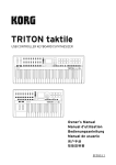
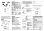
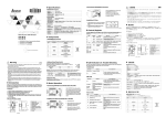
2. The AC power input for PLC MPU and I/O extension modules should be ON or OFF at the same time.
3. Use wires of 1.6mm (or longer) for the grounding. The power shutdown of less than 10ms will not affect the
operation of the PLC. However, power shutdown time that is too long or the drop of power voltage will stop
the operation of the PLC and all outputs will go OFF. When the power supply turns normal again, the PLC
will automatically return to its operation. Please be aware of the latched auxiliary relays and registers inside
the PLC when programming.
AC Power Input
Dimension
2
.
8
9
0
9
0.5A is the maximum power supply for
+24V power supply output terminal. DO
NOT connect other external power
supplies to this terminal. Every input
terminal requires 6 ~ 7mA to be driven;
e.g. the 16-point input will require
approximately 100mA. Therefore, +24V
cannot give output to extermal load that is
more than 400A.
7
100~240 VAC
82. 2
129 .2
148
Unit: mm
Specifications
Safety Wiring
Electrical Specification
Model
Since a PLC controls many devices, actions of any device may affect actions of other devices, and the
breakdown of any one device may cause the breakdown of the whole auto-control system and danger.
Therefore, we suggest you wire a protection circuit at the power input terminal, as shown in the figure below.
32EH002-L
Item
5
100 ~ 240VAC (-15% ~ 10%); 50/60Hz ± 5%
Fuse capacity
2A/250VAC
Power consumption
60VA
DC24V current supply
500mA
Power protection
DC24V; output short-circuited
Withstand voltage
1,500V AC (Primary-Secondary); 1,500V AC (Primary-PE); 500V AC (Secondary-PE)
Insulation resistance
> 5MΩ (all I/O point-to-ground: 500V DC)
Noise immunity
ESD: 8KV Air Discharge; EFT: Power Line: 2KV, Digital I/O: 1KV, Analog &
Communication I/O: 250V; Damped-Oscillatory Wave: Power Line: 1KV, Digital I/O: 1KV,
RS: 26MHz ~ 1GHz, 10V/m
Earth
The diameter of grounding wire shall not be less than that of L, N terminal of the power.
(When many PLCs are in use at the same time, please make sure every PLC is properly
grounded.)
Operation/storage
Operation: 0ºC ~ 55ºC (temperature); 50 ~ 95% (humidity); pollution degree 2
Storage: -25 ºC ~ 70 ºC (temperature); 5 ~ 95% (humidity)
Input Point Wiring
Vibration/shock immunity
International standards:IEC61131-2,IEC68-2-6 (TEST Fc)/IEC61131-2 & IEC68-2-27
(TEST Ea)
There are two types of DC inputs, SINK and SOURCE.
Weight (g)
R/T: 670/636
MC
1
MC
20kHz
*3
Input impedance
Active Level
Response time/
noise immunity
Warning
ENGLISH
program and instructions designed for DVP-EH2-L are compatible with those of DVP-EH2 series, and please refer to
"DVP-PLC Application Manual: Programming”. For how to purchase its peripheral devices, please refer to this
instruction sheet or “DVP-PLC Application Manual: Special Modules".
DVP-EH2-L is an OPEN TYPE device and therefore should be installed in an enclosure free of airborne dust,
humidity, electric shock and vibration. The enclosure should prevent non-maintenance staff from operating the device
(e.g. key or specific tools are required for opening the enclosure) in case danger and damage on the device may
occur.
DO NOT connect input AC power supply to any of the I/O terminals; otherwise serious damage may occur. Check all
the wiring again before switching on the power and DO NOT touch any terminal when the power is switched on.
Make sure the ground terminal
is correctly grounded in order to prevent electromagnetic interference.
*1
*2
4.7kΩ
3.3kΩ
4.7kΩ
Off On
> 4mA (16.5V)
> 6mA (18.5V)
> 4mA (16.5V)
On Off
< 1.5mA (8V)
< 2.2mA (8V)
< 1.5mA (8V)
Off On
< 8us
< 3.5us
< 7.5us
On Off
< 60us
< 20us
< 7.5us
6
Low speed
Max. frequency
High speed*
10kHz
Output indicator
Current specification
Max. output
delay time
20us
On Off
30us
DC Signal IN
*3: The bandwidth of the input
points other than the
high-speed input points listed
above is 10kHz.
*4: Input points X0 ~ X7and X10 ~
X17 can conduct 10 ~ 60ms
digital filter adjustment.
Single common port relay output
5 ~ 30V DC
< 250V AC, 30V DC
Photo coupler isolation
Magnetic isolation
0.2us
1.5×105 times (5A 30V DC)
5×105 times (3A 120V AC)
3×104 times (5A 250V AC)
9
10
4
8
S/S X0
DVP-**-**-**-R
LED
6
C0
2
M C1
2
.
8
9
M C2
10
Emergency stop: Uses external switch
Fuse: Uses 5 ~ 10A fuse at the common port of output contacts to protect the output circuit
Varistor: To reduce the interference on AC load
Empty terminal: not in use
DC power supply
Neon indicator
Incandescent light (resistive load)
Below 6.2
Memory card port
6
POWER/RUN/BAT.LOW/ERROR indicator
9
COM1 (RS-232)
10
COM2 (RS-485)
3
Battery socket
7
4
Function card mounting hole
8
Extension module connection port
11
Run/Stop switch
Left-side Extension module connection port
12
VR0/VR1
5
Y1 C1 Y4 Y5 Y6
LED
MC1
1. Use O-type or Y-type terminal. See the figure in the left hand side for its
specification. PLC terminal screws should be tightened to 5 ~ 8 kg-cm (4.3 ~
6.9 in-Ibs) and please use only 60/75ºC copper conductor.
2. DO NOT wire empty terminal • . DO NOT place the input signal cable and
output power cable in the same wiring circuit.
3. DO NOT drop tiny metallic conductor into the PLC while screwing and wiring.
Tear off the sticker on the heat dissipation hole for preventing alien
substances from dropping in, to ensure normal heat dissipation of the PLC.
Power Input Wiring
The power input of DVP-EH2-L PLC is AC. When operating the PLC, please make sure that:
1. The input voltage should be current and its range should be 100 ~ 240V AC. The power should be
connected to L and N terminals. Wiring AC110V or AC220V to +24V terminal or input terminal will result in
serious damage on the PLC.
Y7
< 0.3A
4
1
C0
MC2
4
2
3
3
2. PNP
3.2 Wiring Notes
5
Direct mounting hole
Y0
5
Up0
8
Mounting screw
C0 Y0
LOAD
Up 0 Zp 0
Y0
Y 1 Up 1 Zp 1
5
Y 10 Y11
< 0.3A
LED
To suit M3.5 screw terminals
2
5
1. NPN
Please install PLC in an enclosure with sufficient space around it to allow heat
dissipation as shown in the figure.
Wiring:
1
internal program, to ensure safety protection in case of any unexpected errors.
TRANSISTOR OUTPUT
Below 6.2
11 Run/Stop
開關
12 VR0/VR1
7
129 .2
How to screw: Please use M4 screw according to the dimension of the product.
> 50mm
> 50mm
9 COM1 (RS-232)
10 COM2 (RS-485)
0
9
7
RELAY OUTPUT
Transistor (T) contact circuit wiring
DVP series PLC can be secured to a cabinet by using the DIN rail of 35mm in height and
7.5mm in depth. When mounting PLC to DIN rail, be sure to use the end bracket to stop any
side-to-side movement of PLC and reduce the chance of wires being loosen. A small retaining
clip is at the bottom of PLC. To secure PLC to DIN rail, place the clip onto the rail and gently
push it up. To remove it, pull the retaining clip down and gently remove PLC from DIN rail, as
shown in the figure.
DVP MPU
8
記憶卡插槽
電源、運行、錯誤及電池狀態指示
擴充機連接口
左側擴充機連接口
4
8
Input indicator
DIN rail (35mm)
7
C1 Y3 Y4 C2 Y6 Y7
6
How to install DIN rail:
10
5
6
外觀及尺寸
3
1
3.1 How to Mount & Wiring Notes
Communication port cover
8
12
機身固定螺絲
直接固定孔
電池插槽
功能卡固定孔
9
3
Extension module connection port cover
DIN rail clip
4
5
C0 Y0 Y1
2
POWER
RY
I/O terminal No.
9
4
X2
Relay (R) contact circuit wiring
5
12
X1
11
Source Type
4
1
4
+24V 24G
X0
I/O terminals
7
11
S/S
Sourcing
3
9
2
S/S
Manually exclusive output: Uses external circuit and forms an interlock, together with the PLC
6
3
3
Installation & Wiring
2
1
2
Function card/memory card cover
> 50mm
5
1
+5V
2
> 50mm
10
24VDC
24G
* Only Y0 and Y2 support high-speed output.
8
2
SOURCE
+24V
Battery socket cover
Output indicator
9
X2
Sink Type
1
7
X1
Wiring loop
A C power supply
8
3
S/S X0
Input point loop equivalent circuit
SOURCE mode
(common port for current output S/S)
1
3
+24V 24G
Flywheel diode: To extend the life span of contact
N/A
N/A
7
7
10ms
Electrical life
6
2
Wiring loop
S/S
LOAD
Product Profile & Outline
5
5
Y0
2×10⁷ times (without load)
1
8
3
+5V
X0
Load ON/OFF control
N/A
4
9
8
10
X0
2mA/DC power supply
Mechanical life
3
24VDC
*2: The bandwidth of input points
X0, X1, X4, and X5 is 60kHz.
Introduction
2
8
4
1
SINK mode
(common port for current input S/S)
200kHz
Over-current protection
7
10
電池插槽上蓋
功能卡∕記憶卡上蓋
輸出∕入端子
輸入∕輸出端子編號
擴充機連接口上蓋
輸入點指示燈
輸出點指示燈
DIN 軌固定扣
通訊口上蓋
固定 DIN 軌糟 (35mm)
6
< 1kHz, 0.3A/1 point @ 40°C
2A/1 point (5A/COM)
0.3A/1 point @ 40ºC
≥ 1kHz, 30mA/1 point @ 40°C 75VA (conductive), 90W (resistive)
Off On
6
9
SINK
+24V
*1: The bandwidth of input points
X10, X11, X14, and X15 is
20kHz.
--
Insulation
5
7
The device is made of electromagnetic contactor and relay as the
switch to prevent the instability of system when the power is
intermittently supplied.
Input point loop equivalent circuit
LED display; light on = ON, light off = OFF
Min. load
Working voltage
4
Output Point Wiring
Single common port transistor output
Items
3
5
6
10
X0
Output Point Specification
Specification
This instruction sheet only provides introductory information on electrical specifications, functions, and wiring. The
2
DVP-PLC (main processing unit)
Earth
Power supply AC: 100 ~ 240VAC
7
Note
60kHz
24VDC
Input point configuration
1
4
3
24G
LED display; light on = ON, light off = OFF
Input voltage (±10%)
2
1
System circuit isolation device
MC
Sinking
Change wiring from S/S to SINK or SOURCE
Input indicator
3
S/S
10kHz
Input wiring type
產品外觀及各部介紹
This button can cut off the system power supply when accidental
emergency takes place.
DC Signal IN
24VDC single common port input
Items
2
N
Input Point Specification
Specification
產品簡介
)
1
L
相容,詳細說明請見 DVP-PLC 應用技術手冊【程式篇】,選購之週邊裝置詳細說明請見該產品隨機手冊或
DVP-PLC 應用技術手冊【特殊模組篇】。
機殼,因此使用者使用本機時,必須將之安裝於具防塵、防潮及免於電擊∕衝
擊意外之外殼配線箱內。另必須具備保護措施(如:特殊之工具或鑰匙才可打開)防止非維護人員操作或意
外衝擊本體,造成危險及損壞。
交流輸入電源不可連接於輸入∕出信號端,否則可能造成嚴重損壞,請在上電之前再次確認電源配線。請勿
在上電時觸摸任何端子。本體上之接地端子 務必正確的接地,可提高產品抗雜訊能力。
Power indicator
Emergency stop
8
Guar d
Limit
繁體中文
本機為開放型 (OPEN TYPE)
AC power supply load
Power circuit protection fuse (3A
Power supply voltage
4
注意事項
本使用說明書僅提供電氣規格、功能規格、安裝配線部份說明,其它詳細之程式設計及指令與 DVP-EH2 系列
MC1
Y0
LOAD
4
1
ZP 0
3
3
2
TRANSISTOR OUTPUT
DC power supply
Emergency stop
Circuit protection fuse
Flywheel diode + inductive load
Manually exclusive output: Uses external circuit and forms an interlock, together with the PLC
internal program, to ensure safety protection in case of any unexpected errors.
MC2
規格
尺寸單位:mm
電氣規格
機種
項目
電源電壓
電源保險絲容量
消耗電力
DC24V 供應電流
電源保護
突波電壓耐受量
絕緣阻抗
雜訊免疫力
接地
操作∕儲存環境
耐振動/衝擊
重量(約), (g)
82. 2
14 8
輸入點規格
規格
項目
輸入接線型式
輸入動作指示
輸入信號電壓 (±10%)
輸入點配置
輸入阻抗
動作位準 OffOn
OnOff
反應時間 OffOn
雜訊抑制 OnOff
DVP32EH002-L
100 ~ 240V AC (-15% ~ 10%); 50/60Hz ± 5%
2A/250V AC
60VA
500mA
DC24V
輸出具短路保護
1,500V AC (Primary-Secondary); 1,500V AC (Primary-PE); 500V AC (Secondary-PE)
5M
Ω以上(所有輸出∕入點對地之間 500V DC)
ESD: 8KV Air Discharge; EFT: Power Line: 2KV, Digital I/O: 1KV, Analog & Communication I/O:
250V; Damped-Oscillatory Wave: Power Line: 1KV, Digital I/O: 1KV, RS: 26MHz ~ 1GHz, 10V/m
接地配線之線徑不得小於電源端 L, N 之線徑(多台 PLC 同時使用時,請務必單點接地)
操作:0°C ~55°C(溫度),50 ~ 95%(濕度),污染等級 2;
儲存:-25°C ~70°C(溫度),5 ~ 95%(濕度)
國際標準規範 IEC 61131-2, IEC 68-2-6 (TEST Fc) / IEC 61131-2 & IEC 68-2-27 (TEST Ea)
R/T: 670/636
24VDC
10kHz
單端共點輸入
20kHz
註3
*
24V DC
註1
*
備註
60kHz
由端子 S/S 變換接線為 SINK 或 SOURCE
LED 顯示;燈亮表示為 ON ,不亮表示為 OFF
註2
*
4.7kΩ
3.3kΩ
4.7kΩ
> 4mA (16.5V)
> 6mA (18.5V)
> 4mA (16.5V)
< 1.5mA (8V)
< 2.2mA (8V)
< 1.5mA (8V)
< 8 us
< 3.5 us
< 7.5 us
< 60 us
< 20 us
< 7.5 us
註 1:輸入點 X10, X11, X14, X15
之頻寬為 20kHz
註 2:輸入點 X0, X1, X4, X5 之頻
寬為 60kHz
*註 3:除上述說明高速輸入點之
外,其餘輸入為 10kHz
*註 4:輸入點 X0~X17 可作 10 ~ 60
ms 數位濾波調整
*
*
輸出點規格
規格
項目
最高交換(工作)頻率
輸出動作指示
最小負載
工作電壓
隔離方式
電流規格
最大輸出 OffOn
延遲時間 OnOff
輸出過電流保護
機械壽命
單端共點電晶體輸出
低速
10kHz
單端共點繼電器輸出
負載 ON/OFF 控制使用
高速 *註
200kHz
LED
顯示, 燈亮表示為’ON’, 不亮表示為’OFF’
2mA/DC
5 ~ 30VDC
點@ 40°C
< 1kHz, 0.3A/1
點@ 40°C
點@ 40°C
≥ 1kHz, 30mA/1
20us
3.1
N/A
次(無負載)
次 (5A 30VDC)
次 (3A 120VAC)
3 × 10 次 (5A 250VAC)
2 × 10⁷
N/A
5 × 10⁵
N/A
4
安裝及配線
盤內安裝
2.
8
9
3
1
4
突波吸收二極體:可增加接點壽命
緊急停止:使用外部開關
保險絲:使用 5 ~ 10A 的保險絲容量於輸出接點的共用點,保護輸出點回路。
突波吸收器:可減少交流負載上的雜訊
空端子:不使用
直流電源供給
指示燈:氖燈
交流電源供給
白熾燈(電阻性負載)
互斥輸出:利用外部電路形成互鎖,配合 PLC 內部程式,確保任何異常突發狀況發生時,均有安全
的保護措施。
電晶體 (T) 接點回路配線
5
C0 Y0
LOAD
觸
發
回
路
Y0
Y1
129 .2
4
1
M C2
4
2
3
3
2. PNP
5
直接鎖鏍絲方式:請依產品外型尺寸並使用 M4 鏍絲。
端子配線:
1. 輸出∕入配線端請使用 O 型或 Y 型端子,端子規格如左所示。PLC 端子鏍絲扭
以下
力為 5 ~ 8 kg-cm (4.3 ~ 6.9 in-lbs)。只能使用 60/75°C 的銅導線。
使用 2. 空端子 • 請勿配線。輸入點信號線與輸出點等動力線請勿置於同一線糟內。
以下
3. 鎖鏍絲及配線時請避免微小的金屬導體掉入 PLC 內部,並在配線完成後,將位
於 PLC 上方散熱孔位置的防異物掉入之貼紙撕去,以保持散熱良好。
UP0
觸
發
回
路
LED
Up0 Zp 0
Y0
Y1 Up1 Zp1
5
Y10 Y11
< 0.3A
MC1
MC2
Y0
LOAD
3
2
3
规格
项目
输入接线型式
输入动作指示
输入信号电压 (±10%)
输入点配置
输入阻抗
动作位准 OffOn
OnOff
反应时间 OffOn
杂讯抑制 OnOff
TRANSISTOR OUTPUT
直流電源供應
緊急停止
電路回路保護用保險絲
突波吸收二極體 + 電感性負載
互斥輸出:利用外部電路形成互鎖,配合 PLC 內部程式,確保任何異常突發狀況發生時,均有安全
的保護措施。
6.2
M3.5
6.2
注意事項
電源端輸入配線
3.2
系列 PLC 電源輸入為交流輸入,在使用上應注意下列事項:
1. 交流電源輸入電壓,範圍寬廣 (100 ~ 240VAC),電源請接於 L、N 兩端,如果將 AC110V 或 AC220V 接至+24V
DVP-EH2
注意事項
2.
電源供應輸出端,最大為
,請勿將其它的外部電源連接至
此端子。每個輸入點驅動必須 6 ~
7mA,若以 16 點輸入計算,大約需
100mA,因此+24V 輸出給外部負載
不可大於 400mA。
+24V
0.5A
安全配線回路
由於 PLC 控制許多裝置,任一裝置的動作可能都會影響其它裝置的動作。因此任一裝置的故障都可能會造成整個
自動控制系統失控,甚至造成危險。所以在電源端輸入回路,建議配置如下的保護回路:
5
MC
1
4
8
2
Guard
Limi t
MC
3
MC
1
L
7
N
6
輸入點之配線
产品外观及各部介绍
2
交流電源負載
電源回路保護用保險絲 (3A)
電源指示燈
緊急停止
為預防突發狀況發生,設置一緊急停止按鈕,可在狀況發生時,
切斷系統電源。
系統回路隔離裝置
使用電磁接觸器、繼電器等開關作為系統電源回路隔離裝置,可
防止電源斷續供應時,造成系統的不穩定。
DVP PLC 本體
第三種接地
電源供應:交流(AC):100 ~ 240V AC;50/60Hz
輸入點回路等效電路
2
1
Sinking
4
24VDC
6
9
10
9
4
8
3
10
5
X0
S/S
X0
X1
X2
2
SOURCE
S/S
S/S
+24V 24G
Sourcing
模式
(電流流出共用端 S/S)
SOURCE
11
8
4
12
S/S X0 X1 X2
1
2
X0
Source Type
3
4
机身固定螺丝
直接固定孔
电池插槽
功能卡固定孔
5
6
7
8
记忆卡插槽
电源、运行、错误及电池状态指示
扩充机连接口
左侧扩充机连接口
24VDC
10kHz
9 COM1 (RS-232)
11 Run/Stop
开关
12 VR0/VR1
6
24VDC
注1
注2
*
*
*
4.7kΩ
3.3kΩ
4.7kΩ
> 4mA (16.5V)
> 6mA (18.5V)
> 4mA (16.5V)
< 1.5mA (8V)
< 2.2mA (8V)
< 1.5mA (8V)
< 8us
< 3.5us
< 7.5us
< 60us
< 20us
< 7.5us
低速
单端共点晶体管输出
10kHz
输入点之配线
*
单端共点继电器输出
负载 ON/OFF 控制使用
点@ 40°C
≥ 1kHz, 30mA/1 点@ 40°C
0.2us
10ms
< 1kHz, 0.3A/1
N/A
N/A
次(无负载)
次 (5A 30V DC)
次 (3A 120V AC)
3 × 10 次 (5A 250V AC)
2 × 10⁷
1.5 × 10⁵
N/A
24VDC
X0
S/S
SINK 模式
(电流流入共享端 S/S)
直流形式 DC Signal IN
X0
+5V
+24V 24G
S/S X0 X1 X2
Sink Type
输入点回路等效电路
X0
配线回路
SOURCE
+24V
24VDC
+5V
24G
S/S
S/S
Sourcing
模式
(电流流出共享端 S/S)
+24V 24G
S/S X0 X1 X2
X0
SOURCE
Source Type
输出点的配线
继电器 (R) 接点回路配线
DVP-**-**-**-R
5
2
LOAD
电源
电磁性隔离
2A/1 点 (5A/COM)
75VA(电感性), 90W(电阻性)
30us
配线回路
SINK
+24V
LED
C0
C1 Y3 Y4 C2
Y0 Y1
Y6 Y7
9
3
POWER
RY
6
C0
3
1
2
< 250V AC, 30V DC
光耦合隔离
20us
交流电源负载
电源回路保护用保险丝 (3A)
电源指示灯
紧急停止
为预防突发状况发生,设置一紧急停止按钮,可在状况发生时,
切断系统电源。
系统回路隔离装置
使用电磁接触器、继电器等开关作为系统电源回路隔离装置,可
防止电源断续供应时,造成系统的不稳定。
DVP PLC 本体
第三种接地
电源供应:交流(AC):100 ~ 240V AC;50/60Hz
Y0
2mA/DC
5 ~ 30V DC
点@ 40°C
注 1:输入点 X10, X11, X14, X15
之频宽为 20kHz
注 2:输入点 X0, X1, X4, X5 之频
宽为 60kHz
*注 3:除上述说明高速输入点之外,
其余输入为 10kHz
*注 4:输入点 X0~X17 可作 10 ~ 60
ms 数字滤波调整
*
显示, 灯亮表示为’ON’, 不亮表示为’OFF’
-
0.3A/1
+5V
输入点回路等效电路
直流形式 DC Signal IN
高速 *注
200kHz
LED
X2
输入点之入力信号为直流电源 DC 输入,DC 型式共有两种接法:SINK 及 SOURCE,其定义如下:
备注
60kHz
由端子 S/S 变换接线为 SINK 或 SOURCE
LED 显示;灯亮表示为 ON ,不亮表示为 OFF
注3
X1
24G
单端共点输入
20kHz
5 × 10⁵
4
盘内安装及配线
MC1
MC2
10
4
8
7
RELAY OUTPUT
突波吸收二极管:可增加接点寿命
紧急停止:使用外部开关
保险丝:使用 5 ~ 10A 的保险丝容量于输出接点的共享点,保护输出点回路。
突波吸收器:可减少交流负载上的噪声 空端子:不使用
直流电源供给
指示灯:氖灯
交流电源供给
白炽灯(电阻性负载)
互斥输出:利用外部电路形成互锁,配合 PLC 内部程序,确保任何异常突发状况发生时,均有安全
的保护措施。
晶体管 (T) 接点回路配线
1. NPN
铝轨之安装方法:
适合 35mm 之 DIN 铝轨。主机欲挂于铝轨时,先将 PLC 下方的固定塑料片压入,再将 PLC
由上方挂上再往下压即可。欲取下 PLC 时,PLC 底部下的固定塑料片,以起子插入凹槽,
向上撑开即可,该固定机构塑料片为保持型,当所有的固定片撑开后,再将 PLC 往上外方
取出,如右图所示:
LED
DIN
5
C0 Y0
LOAD
触
发
回
路
Y0
Y1
4
1
C0
5
C 1 Y 4 Y5 Y 6
MC1
< 0.3A
Y7
M C2
4
2
TRANSISTOR OUTPUT
3
3
2. PNP
> 50mm
PLC 在安装时,请装配于封闭式的控制箱内,其周围应保持一定的空间,(如左图所
示),以确保 PLC 散热功能正常。
注意事项
电源端输入配线
3.2
10 COM2 (RS-485)
7
N
Sinking
6 .2
+5V
24G
MC
S/S
M3 .5
9
L
R/T: 670/636
6 .2
1
3
配線回路
3
1
直接锁镙丝方式:请依产品外型尺寸并使用 M4 镙丝。
端子配线:
1. 输出/入配线端请使用 O 型或 Y 型端子,端子规格如左所示。PLC 端子镙丝扭
以下
力为 5 ~ 8 kg-cm (4.3 ~ 6.9 in-lbs)。只能使用 60/75°C 的铜导线。
使用 2. 空端子 • 请勿配线。输入点信号线与输出点等动力线请勿置于同一线糟内。
以下
3. 锁镙丝及配线时请避免微小的金属导体掉入 PLC 内部,并在配线完成后,将位
于 PLC 上方散热孔位置的防异物掉入的贴纸撕去,以保持散热良好。
7
Sink Type
輸入點回路等效電路
3.1
MC
以上(所有输出/入点对地之间 500VDC)
接地配线的线径不得小于电源端 L, N 的线径(多台 PLC 同时使用时,请务必单点接地)
操作:0°C ~ 55°C (温度),50 ~ 95% (湿度),污染等级 2;
储存:-25°C ~ 70°C (温度),5 ~ 95% (湿度)
国际标准规范 IEC61131-2, IEC 68-2-6 (TEST Fc)/IEC61131-2 & IEC 68-2-27 (TEST Ea)
DVP MPU
6
24G
5 MΩ
2
Guard
Limit
安裝及配線
> 50mm
+5V
+24V
8
输出具短路保护
ESD: 8KV Air Discharge; EFT: Power Line: 2KV, Digital I/O: 1KV, Analog & Communication I/O:
250V
Damped-Oscillatory Wave: Power Line: 1KV, Digital I/O: 1KV, RS: 26MHz ~ 1GHz, 10V/m
> 50mm
S/S
24VDC
10
1
1,500V AC (Primary-Secondary); 1,500V AC (Primary-PE); 500V AC (Secondary-PE)
注:高速输出点仅限 Y0、Y2 支援。
*
MC
4
接点寿命
2
1
+24V
8
电池插槽上盖
功能卡/记忆卡上盖
输出/入端子
输入/输出端子编号
扩充机连接口上盖
输入点指示灯
输出点指示灯
DIN 轨固定扣
通讯口上盖
固定 DIN 轨糟 (35mm)
5
2A/250V AC
500mA
X0
安全配线回路
60VA
DC24V
S/S
DC/DC
100 ~ 240V AC (-15% ~ 10%); 50/60Hz ± 5%
> 50mm
24G
X0
7
8
X0
SINK 模式
(電流流入共用端 S/S)
直流形式 DC Signal IN
5
7
SINK
+24V
3
5
6
配線回路
S/S
1
4
3
+24V 24G
2.0 A
规格
项目
最高交换(工作)频率
输出动作指示
最小负载
工作电压
隔离方式
电流规格
最大输出 OffOn
延迟时间 OnOff
输出过电流保护
机械寿命
產品簡介
N
由于 PLC 控制许多装置,任一装置的动作可能都会影响其它装置的动作。因此任一装置的故障都可能会造成整个
自动控制系统失控,甚至造成危险。所以在电源端输入回路,建议配置如下的保护回路:
DVP32EH002-L
输出点规格
兼容,详细说明请见 DVP-PLC 应用技术手册【程序篇】,选购外围装置详细说明请见该产品随机手册或
DVP-PLC 应用技术手册【特殊模块篇】。
本机为开放型 (OPEN TYPE) 机壳,因此使用者使用本机时,必须将之安装于具防尘、防潮及免于电击/冲
击意外之外壳配线箱内。另必须具备保护措施(如:特殊之工具或钥匙才可打开)防止非维护人员操作或意
外冲击本体,造成危险及损坏。
交流输入电源不可连接于输入/出信号端,否则可能造成严重损坏,请在上电之前再次确认电源配线。请勿
在上电时触摸任何端子。本体上之接地端子 务必正确的接地,可提高产品抗噪声能力。
輸入點之入力信號為直流電源 DC 輸入,DC 型式共有兩種接法:SINK 及 SOURCE,其定義如下:
直流形式 DC Signal IN
简体中文
本使用说明书仅提供电气规格、功能规格、安装配线部份说明,其它详细之程序设计及指令与 DVP-EH2 系列
输入点规格
4
1
ZP 0
尺寸单位:mm
148
規格
机种
项目
电源电压
电源保险丝容量
消耗电力
DC24V 供应电流
电源保护
突波电压耐受量
绝缘阻抗
噪声免疫力
接地
操作/储存环境
耐振动/冲击
重量(约), (g)
Y7
L
82. 2
电气规格
5
C 1 Y 4 Y5 Y 6
MC1
< 0.3A
C0
TRANSISTOR OUTPUT
在安裝時,請裝配於封閉式之控制箱內,其周圍應保持一定之空間,(如左圖所
示),以確保 PLC 散熱功能正常。
100~240 VAC
电源供应输出端,最大
为 ,请勿将其它的外部电
源连接至此端子。每个输入点
驱动必须 6 ~ 7mA,若以 16
点输入计算,大约需 100mA,
因此+24V 输出给外部负载不
可大于 400mA。
+24V
0.5A
100~240VAC
LED
端或輸入點端,將造成 PLC 嚴重損壞,請使用者特別注意。
主機及 I/O 擴充機之交流電源輸入請同時作 On 或 Off 的動作。
主機之接地端使用 1.6mm 以上之電線接地。
4. 當停電時間低於 10ms 時,PLC 不受影響繼續運轉,當停電時間過長或電源電壓下降將使 PLC 停止運轉,輸
出全部 Off,當電源恢復正常時,PLC 亦自動回復運轉。(PLC 內部具有停電保持的輔助繼電器及暫存器,使
用者在作程式設計規劃時應特別注意使用。)
交流電源輸入型式
端或输入点端,将造成 PLC 严重损坏,请使用者特别注意。
主机及 I/O 扩充机的交流电源输入请同时作 On 或 Off 的动作。
主机的接地端使用 1.6mm 以上的电线接地。
当停电时间低于 10ms 时,PLC 不受影响继续运转,当停电时间过长或电源电压下降将使 PLC 停止运转,输
出全部 Off,当电源恢复正常时,PLC 亦自动回复运转。(PLC 内部具有停电保持的辅助继电器及缓存器,使
用者在作程序设计规划时应特别注意使用。)
交流电源输入型式
7
7
1. NPN
3.
0
9
MC2
MC1
RELAY OUTPUT
PLC
> 50mm
> 50mm
9
3
6
8
鋁軌之安裝方法:
適合 35mm 之 DIN 鋁軌。主機欲掛於鋁軌時,先將 PLC 下方之固定塑膠片壓入,再將 PLC
由上方掛上再往下壓即可。欲取下 PLC 時,PLC 底部下之固定塑膠片,以起子插入凹槽,向
上撐開即可,該固定機構塑膠片為保持型,當所有的固定片撐開後,再將 PLC 往上外方取出,
如右圖所示:
> 50mm
Y6 Y7
10
DIN
DVP MPU
Y3 Y4 C2
1.5 × 10⁵
> 50mm
C1
2
10ms
註:高速輸出點僅限 Y0、Y2 支援。
Y0 Y1
接點壽命
*
C0
POWER
RY
C0
電磁性隔離
2A/1 點 (5A/COM)
;90W(電阻性)
75VA(電感性)
0.2us
30us
4.
5
2
LOAD
Y0
LED
2.
3.
DVP-**-**-**-R
電源
外观及尺寸
< 250VAC, 30VDC
光耦合隔離
0.3A/1
輸出點之配線
繼電器 (R) 接點回路配線
系列 PLC 电源输入为交流输入,在使用上应注意下列事项:
交流电源输入电压,范围宽广(100 ~ 240VAC),电源请接于 L、N 两端,如果将 AC110V 或 AC220V 接至+24V
DVP-EH2
1.
5
LED
触
发
回
路
UP0
Up0 Zp 0
Y0
Y1 Up1 Zp1
5
Y10 Y11
< 0.3A
MC1
MC2
Y0
LOAD
4
1
ZP 0
2
3
3
TRANSISTOR OUTPUT
直流电源供应
紧急停止
电路回路保护用保险丝
突波吸收二极管 + 电感性负载
互斥输出:利用外部电路形成互锁,配合 PLC 内部程序,确保任何异常突发状况发生时,均有安全的
保护措施。