1
Users’ Guide for the Programmable MUX (PMUX)
on the M I/O Aggregator
Dell Networking OS version 9.3(0.0)
Copyright © 2014 Dell Inc. All rights reserved. This product is protected by U.S. and
international copyright and intellectual property laws. Dell and the Dell logo are trademarks
of Dell Inc. in the United States and/or other jurisdictions. All other marks and names
mentioned herein may be trademarks of their respective companies.
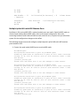
Introduction
This document provides configuration instructions and examples for the Programmable MUX
(PMUX mode) for the Dell Networking M I/O Aggregator using Dell Networking OS version
9.3(0.0). This document includes the following Programmable MUX features:
•
Programmable MUX (PMUX)
o Multiple uplink link aggregation group (LAGs)
10G member ports
40G member ports
o Uplink failure detection (UFD)
o Virtual local area network (VLAN) configurations on a physical port/port-channel
o Virtual link trunking (VLT)
o Stacking
o N-port identifier virtualization (NPIV)
NOTE: For more information, refer to the M IO Aggregator Command Line Interface for Dell
Networking OS Version 9.2(0.2)/9.2(0.0) and the M IO Aggregator Configuration Guide for Dell
Networking OS Version 9.2(0.2)/9.2(0.0).
I/O Aggregator (IOA) Programmable MUX (PMUX) Mode
IOA PMUX is a mode that provides flexibility of operation with added configurability. This
involves creating multiple LAGs, configuring VLANs on uplinks and the server side, configuring
data center bridging (DCB) parameters, and so forth.
By default, IOA starts up in IOA Standalone mode. You can change to PMUX mode by executing
the following commands and then reloading the IOA. After the IOA reboots, the IOA operates in
PMUX mode. PMUX mode supports both stacking and VLT operations.
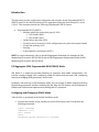
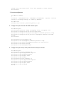
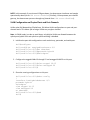
Configuring and Changing to PMUX Mode
After the IOA is operational in the default Standalone mode:
1. Connect the terminal to the console port on the IOA to access the CLI and enter the
following commands:
Login: username
Password: *****
Dell> enable
Dell#
Dell#show system stack-unit 0 iom-mode
Unit Boot-Mode Next-Boot
-----------------------------------------------0 standalone standalone
Dell#
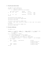
2. Change IOA mode to PMUX mode.
Dell(conf)# stack-unit 0 iom-mode programmable-mux
Where stack-unit 0 defines the default stack-unit number.
3. Delete the startup configuration file.
Dell# delete startup-config
4. Reboot the IOA by entering the reload command.
Dell# reload
5. Repeat the above steps for each member of the IOA in PMUX mode.
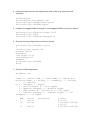
After system is up, you can see the PMUX mode status:
Dell#sh system stack-unit 0 iom-mode
Unit
Boot-Mode
Next-Boot
-----------------------------------------------0
programmable-mux
programmable-mux
Dell#
The IOA is now ready for PMUX operations.
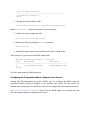
Configuring the Commands without a Separate User Account
Starting with Dell Networking OS version 9.3(0.0), you can configure the PMUX mode CLI
commands without having to configure a new, separate user profile. The user profile you
defined to access and log in to the switch is sufficient to configure the PMUX mode commands.
The IOA PMUX Mode CLI Commands section lists the PMUX mode CLI commands that you
can now configure without a separate user account.
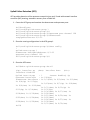
Multiple Uplink LAGs
Unlike IOA Automated modes (Standalone, VLT, and Stacking Modes), the IOA Programmable
MUX can support multiple uplink LAGs. You can provision multiple uplink LAGs.
Note: In order to avoid loops, only disjoint VLANs are allowed between the uplink ports/uplink
LAGs and uplink-to-uplink switching is disabled.
Multiple Uplink LAGs with 10G Member Ports
The following sample commands configure multiple dynamic uplink LAGs with 10G member
ports based on LACP.
1. Bring up all the ports.
Dell#configure
Dell(conf)#int range tengigabitethernet 0/1 - 56
Dell(conf-if-range-te-0/1-56)#no shutdown
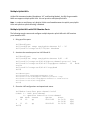
2. Associate the member ports into LAG-10 and 11.
Dell#configure
Dell(conf)#int range tengigabitethernet 0/41 - 42
Dell(conf-if-range-te-0/41-42)#port-channel-protocol lacp
Dell(conf-if-range-te-0/41-42-lacp)#port-channel
10
mode
active
Dell(conf-if-range-te-0/41-42-lacp)#end
Dell#
Dell#configure
Dell(conf)#int tengigabitethernet 0/43
Dell(conf-if-te-0/43)#port-channel-protocol lacp
Dell(conf-if-te-0/43-lacp)#port-channel 11 mode active
Dell(conf-if-te-0/43-lacp)#end
Dell#
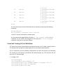
3. Show the LAG configurations and operational status.
Dell#show interface port-channel brief
Codes: L - LACP Port-channel
O - OpenFlow Controller Port-channel
LAG Mode Status
Uptime
Ports
L
10
L3
up
00:01:00
Te 0/41
Te 0/42
L
11
L3
up
00:00:01
Te 0/43
Dell#
(Up)
(Up)
(Up)
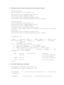
4. Configure the port mode, VLAN, and so forth on the port-channel.
Dell#configure
Dell(conf)#int port-channel 10
Dell(conf-if-po-10)#portmode hybrid
Dell(conf-if-po-10)#switchport
Dell(conf-if-po-10)#vlan tagged 1000
Dell(conf-if-po-10)#link-bundle-monitor enable
Dell#configure
Dell(conf)#int port-channel 11
Dell(conf-if-po-11)#portmode hybrid
Dell(conf-if-po-11)#switchport
Dell(conf-if-po-11)#vlan tagged 1000
% Error: Same VLAN cannot be added to more than one uplink
port/LAG.
Dell(conf-if-po-11)#vlan tagged 1001
Dell(conf-if-po-11)#link-bundle-monitor enable
Dell#show vlan
Codes: * - Default VLAN, G - GVRP VLANs, R - Remote Port
Mirroring VLANs, P - Primary, C - Community, I - Isolated
O - Openflow
Q: U - Untagged, T - Tagged
x - Dot1x untagged, X - Dot1x tagged
o - OpenFlow untagged, O - OpenFlow tagged
G - GVRP tagged, M - Vlan-stack, H - VSN tagged
i - Internal untagged, I - Internal tagged, v - VLT
untagged, V - VLT tagged
*
NUM
1
1000
1001
Dell#
Status
Active
Description
Active
Active
Q
U
U
T
T
Ports
Po10(Te
Po11(Te
Po10(Te
Po11(Te
0/41-42)
0/43)
0/41-42)
0/43)
5. Show LAG member ports utilization.
Dell#show link-bundle-distribution
Link-bundle trigger threshold - 60
LAG bundle - 10
- Inactive
Interface
Utilization[In Percent] - 0
Line Protocol
Alarm State
Utilization[In Percent]
Te 0/41
Te 0/42
Up
Up
LAG bundle - 11
- Inactive
Interface
Te 0/43
Dell#
0
0
Utilization[In Percent] - 0
Line Protocol
Up
Alarm State
Utilization[In Percent]
0
Multiple Uplink LAGs with 40G Member Ports
By default in IOA, native 40G QSFP+ optional module ports are used in Quad (4x10G) mode, to
convert Quad mode to Native 40G mode, refer to the sample configuration. Also note,
converting between Quad mode and Native mode, and vice versa, requires that you reload the
system for the configuration changes to take effect.
The following sample commands configure multiple dynamic uplink LAGs with 40G member
ports based on LACP.
1. Convert the quad mode (4x10G) ports to native 40G mode.
Dell#configure
Dell(conf)#no stack-unit 0 port 33 portmode quad
Disabling quad mode on stack-unit 0 port 33 will make interface
configs of Te 0/33 Te 0/34 Te 0/35 Te 0/36 obsolete after a save
and reload.
[confirm yes/no]:yes
Please save and reset unit 0 for the changes to take effect.
Dell(conf)#no stack-unit 0 port 37 portmode quad
Disabling quad mode on stack-unit 0 port 37 will make interface
configs of Te 0/37 Te 0/38 Te 0/39 Te 0/40 obsolete after a save
and reload.
[confirm yes/no]:yes
Please save and reset unit 0 for the changes to take effect.
Dell(conf)#no stack-unit 0 port 49 portmode quad
Disabling quad mode on stack-unit 0 port 49 will make interface
configs of Te 0/49 Te 0/50 Te 0/51 Te 0/52 obsolete after a save
and reload.
[confirm yes/no]:yes
Please save and reset unit 0 for the changes to take effect.
Dell(conf)#no stack-unit 0 port 53 portmode quad
Disabling quad mode on stack-unit 0 port 53 will make interface
configs of Te 0/53 Te 0/54 Te 0/55 Te 0/56 obsolete after a save
and reload.
[confirm yes/no]:yes
Please save and reset unit 0 for the changes to take effect.
Dell(conf)#
2. Save the configuration.
Dell#write memory
!
01:05:48: %STKUNIT0-M:CP %FILEMGR-5-FILESAVED:
config to startup-config in flash by default
Copied
running-
Dell#reload
Proceed with reload [confirm yes/no]: yes
3. Configure the port-channel with 40G member ports.
Dell#configure
Dell(conf)#interface range fortygige 0/33, fortygige 0/37
Dell(conf-if-range-fo-0/33,fo-0/37)#no shut
Dell(conf-if-range-fo-0/33,fo-0/37)#port-channel-protocol lacp
Dell(conf-if-range-fo-0/33,fo-0/37-lacp)#port-channel 20 mode
active
Dell(conf)#
Dell(conf)#int fortygige 0/49
Dell(conf-if-fo-0/49)#port-channel-protocol lacp
Dell(conf-if-fo-0/49-lacp)#port-channel 21 mode active
Dell(conf-if-fo-0/49-lacp)#
Dell(conf-if-fo-0/49)#no shut
4. Configure the port mode, VLAN, and so forth on the port-channel.
Dell#configure
Dell(conf)#int port-channel 20
Dell(conf-if-po-20)#portmode hybrid
Dell(conf-if-po-20)#switchport
Dell(conf-if-po-20)#no shut
Dell(conf-if-po-20)#ex
Dell(conf)#int port-channel 21
Dell(conf-if-po-21)#portmode hybrid
Dell(conf-if-po-21)#switchport
Dell(conf-if-po-21)#no shut
Dell(conf-if-po-21)#end
Dell#
5. Show the port channel status.
Dell#sh int port-channel br
Codes: L - LACP Port-channel
O - OpenFlow Controller Port-channel
L
LAG
20
L
21
Dell#
Mode
L2
Status
up
Uptime
00:00:53
L2
up
00:00:02
Ports
Fo 0/33
Fo 0/37
Fo 0/49
(Up)
(Up)
(Up)
Dell(conf)#int port-channel 20
Dell(conf-if-po-20)#vlan tagged 1000
Dell(conf-if-po-20)#
Dell(conf-if-po-21)#vlan tagged 1000
% Error: Same VLAN cannot be added to more than
port/LAG.
Dell(conf-if-po-21)#vlan tagged 1001
Dell(conf-if-po-21)#
one uplink
6. Show the VLAN status.
Dell#show vlan
Codes: * - Default VLAN, G - GVRP VLANs, R - Remote Port
Mirroring VLANs, P - Primary, C - Community, I - Isolated
O - Openflow
Q: U - Untagged, T - Tagged
x - Dot1x untagged, X - Dot1x tagged
o - OpenFlow untagged, O - OpenFlow tagged
G - GVRP tagged, M - Vlan-stack, H - VSN tagged
i - Internal untagged, I - Internal tagged, v - VLT untagged,
V - VLT tagged
*
NUM
1
1000
1001
Dell#
Status
Active
Active
Active
Description
Q
U
U
T
T
Ports
Po20(Fo
Po21(Fo
Po20(Fo
Po21(Fo
0/33,37)
0/49)
0/33,37)
0/49)
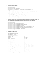
Uplink Failure Detection (UFD)
UFD provides detection of the upstream connectivity loss and, if used with network interface
controller (NIC) teaming, automatic recovery from a failed link.
1. Create the UFD group and associate the downstream and upstream ports.
Dell#configure
Dell(conf)#uplink-state-group 1
Dell(conf-uplink-state-group-1)#
Dell(conf-uplink-state-group-1)#upstream port-channel 128
Dell(conf-uplink-state-group-1)#downstream
tengigabitethernet 0/1-32
2. Show the running configurations in the UFD-group 1.
Dell(conf-uplink-state-group-1)#show config
!
uplink-state-group 1
downstream TenGigabitEthernet 0/1-32
upstream Port-channel 128
Dell(conf-uplink-state-group-1)#
3. Show the UFD status.
Dell#show uplink-state-group detail
(Up): Interface up
(Dwn): Interface down
(Dis):
Interface disabled
Uplink State Group
: 1
Status: Enabled, Up
Upstream Interfaces
: Po 128(Up)
Downstream Interfaces : Te 0/1(Dwn) Te 0/2(Dwn) Te 0/3(Dwn)
Te 0/4(Up) Te 0/5(Up)
Te 0/6(Dwn) Te 0/7(Up) Te 0/8(Dwn)
Te 0/9(Dwn) Te 0/10(Dwn)
Te 0/11(Dwn) Te 0/12(Up) Te
0/13(Up) Te 0/14(Dwn)
Te 0/15(Up)
Te 0/16(Dwn) Te 0/17(Dwn) Te
0/18(Dwn) Te 0/19(Dwn) Te 0/20(Dwn)
Te 0/21(Dwn) Te 0/22(Dwn) Te
0/23(Dwn) Te 0/24(Dwn) Te 0/25(Dwn)
Te 0/26(Dwn) Te 0/27(Dwn) Te
0/28(Dwn) Te 0/29(Dwn) Te 0/30(Dwn)
Te 0/31(Dwn) Te 0/32(Dwn)
Dell#
NOTE: In this example, if port-channel 128 goes down, the downstream interfaces are brought
operationally down (set to UFD error-disabled). Similarly, if the upstream port-channel
goes up, the downstream ports are brought up (cleared from UFD error-disabled).
VLAN Configuration on Physical Ports and Port-Channels
Unlike other Dell Networking OS platforms, IOA allows VLAN configurations on port and portchannel levels. This allows you to assign VLANs to a port/port-channel.
Note: In PMUX mode, In order to avoid loops, only disjoint VLANs are allowed between the
uplink ports/uplink LAGs and uplink-to-uplink switching is disabled.
1. Initialize the port with configurations such as admin up, portmode, and switchport.
Dell#configure
Dell(conf)#int tengigabitethernet 0/1
Dell(conf-if-te-0/1)#no shutdown
Dell(conf-if-te-0/1)#portmode hybrid
Dell(conf-if-te-0/1)#switchport
2. Configure the tagged VLANs 10 through 15 and untagged VLAN 20 on this port.
Dell(conf-if-te-0/1)#vlan tagged 10-15
Dell(conf-if-te-0/1)#vlan untagged 20
Dell(conf-if-te-0/1)#
3. Show the running configurations on this port.
Dell(conf-if-te-0/1)#show config
!
interface TenGigabitEthernet 0/1
portmode hybrid
switchport
vlan tagged 10-15
vlan untagged 20
no shutdown
Dell(conf-if-te-0/1)#end
Dell#
4. Initialize the port-channel with configurations such as admin up, portmode, and
switchport.
Dell#configure
Dell(conf)#int port-channel 128
Dell(conf-if-po-128)#portmode hybrid
Dell(conf-if-po-128)#switchport
5. Configure the tagged VLANs 10 through 15 and untagged VLAN 20 on this port-channel.
Dell(conf-if-po-128)#vlan tagged 10-15
Dell(conf-if-po-128)#
Dell(conf-if-po-128)#vlan untagged 20
6. Show the running configurations on this port-channel.
Dell(conf-if-po-128)#show config
!
interface Port-channel 128
portmode hybrid
switchport
vlan tagged 10-15
vlan untagged 20
shutdown
Dell(conf-if-po-128)#end
Dell#
7. Show the VLAN configurations.
Dell#show vlan
Codes: * - Default VLAN, G - GVRP VLANs, R - Remote Port
Mirroring VLANs, P - Primary, C - Community, I - Isolated
O - Openflow
Q: U - Untagged, T - Tagged
x - Dot1x untagged, X - Dot1x tagged
o - OpenFlow untagged, O - OpenFlow tagged
G - GVRP tagged, M - Vlan-stack, H - VSN tagged
i - Internal untagged, I - Internal tagged, v - VLT
untagged, V - VLT tagged
*
NUM
1
10
Status
Active
Active
11
Active
Description
Q
U
T
T
T
Ports
Te 0/33
Po128(Te 0/41-42)
Te 0/1
Po128(Te 0/41-42)
12
Active
13
Active
14
Active
15
Active
20
Active
T
T
T
T
T
T
T
T
T
U
U
Te 0/1
Po128(Te
Te 0/1
Po128(Te
Te 0/1
Po128(Te
Te 0/1
Po128(Te
Te 0/1
Po128(Te
Te 0/1
0/41-42)
0/41-42)
0/41-42)
0/41-42)
0/41-42)
Dell#
You can remove the inactive VLANs that have no member ports using the following
command:
Dell#configure
Dell(conf)#no interface vlan <vlan-id>
->vlan-id - Inactive VLAN with no member ports
You can remove the tagged VLANs using the no vlan tagged <VLAN-RANGE>
command. You can remove the untagged VLANs using the no vlan untagged
command in the physical port/port-channel.
Virtual Link Trunking (VLT) in PMUX Mode
VLT allows the physical links between two devices (known as VLT nodes or peers) within a
VLT domain to be considered a single logical link to connected external devices.
For VLT operations, use the following configurations on both the primary and secondary
VLT. Ensure the VLTi links are connected and administratively up. VLTi connects the VLT
peers for VLT data exchange.
1. Configure VLTi.
Dell#configure
Dell(conf)#int port-channel 127
Dell(conf-if-po-127)# channel-member fortygige 0/33,37
Dell(conf-if-po-127)# no shutdown
Dell(conf-if-po-127)# end
2. Configure the VLT domain.
Dell#configure
Dell(conf)#vlt domain 1
Dell(conf-vlt-domain)# peer-link port-channel 127
-> VLT peer destination
Dell(conf-vlt-domain)# back-up destination 169.254.31.23
Dell(conf-vlt-domain)#system-mac mac-address
00:01:09:06:06:06
-> unit-id 0 – VLT Primary, unit-id 1 – VLT Secondary
Dell(conf-vlt-domain)# unit-id 0
Dell(conf-vlt-domain)#end
3. Configure the VLT port channel. In the following example, the local and remote VLT
port-channels are the same but you can also use different VLT port-channels.
Dell#configure
Dell(conf)#int port-channel 128
Dell(conf-if-po-128)# portmode hybrid
Dell(conf-if-po-128)# switchport
Dell(conf-if-po-128)# vlt-peer-lag port-channel 128
Dell(conf-if-po-128)# link-bundle-monitor enable
Dell(conf-if-po-128)# no shutdown
Dell(conf-if-po-128)# end
4. Show the VLT peer status.
Dell#show vlt brief
VLT Domain Brief
-----------------Domain ID:
Role:
Role Priority:
ICL Link Status:
HeartBeat Status:
VLT Peer Status:
Local Unit Id:
Version:
Local System MAC address:
Remote System MAC address:
Configured System MAC address:
Remote system version:
Delay-Restore timer:
Peer-Routing :
Peer-Routing-Timeout timer:
Multicast peer-routing timeout:
1
Primary
32768
Up
Up
Up
0
6(2)
00:01:e8:e1:e1:c3
f8:b1:56:0e:b1:7f
00:01:09:06:06:06
6(2)
90 seconds
Disabled
0 seconds
150 seconds
Dell#
5. Configure the secondary VLT.
NOTE: Repeat steps from 1 through 4 on the secondary VLT, ensuring you use the different
backup destination and unit-id.
Dell#show vlt brief
VLT Domain Brief
-----------------Domain ID:
Role:
Role Priority:
ICL Link Status:
HeartBeat Status:
VLT Peer Status:
Local Unit Id:
Version:
Local System MAC address:
Remote System MAC address:
Configured System MAC address:
Remote system version:
Delay-Restore timer:
Peer-Routing :
Peer-Routing-Timeout timer:
Multicast peer-routing timeout:
Dell#
1
Secondary
32768
Up
Up
Up
1
6(2)
f8:b1:56:0e:b1:7f
00:01:e8:e1:e1:c3
00:01:09:06:06:06
6(2)
90 seconds
Disabled
0 seconds
150 seconds
Dell#show vlt detail
Local LAG Id
Peer LAG Id
Local Status
Active VLANs
------------------- ------------ ----------128
128
UP
UP
Dell#
Peer
Status
---------1
Stacking in PMUX Mode
PMUX stacking allows the stacking of two or more IOA units. This allows grouping of multiple
units for high availability. IOA supports a maximum of six stacking units.
NOTE: Prior to configuring the stack-group, ensure the stacking ports are connected and in 40G
native mode.
1. Configure stack groups on all stack units.
Dell#
Dell#configure
Dell(conf)#stack-unit 0 stack-group 0
Dell(conf)#00:37:46: %STKUNIT0-M:CP %IFMGR-6STACK_PORTS_ADDED: Ports Fo 0/33 have been configured as
stacking ports. Please save and reset stack-unit 0 for
config to take effect
Dell(conf)#stack-unit 0 stack-group 1
Dell(conf)#00:37:57: %STKUNIT0-M:CP %IFMGR-6STACK_PORTS_ADDED: Ports Fo 0/37 have been configured as
stacking ports. Please save and reset stack-unit 0 for
config to take effect
Dell(conf)#end
Dell#00:38:16: %STKUNIT0-M:CP %SYS-5-CONFIG_I: Configured
from console
2. Reload the stack units.
Dell#reload
Proceed with reload [confirm yes/no]: yes
3. Show the units stacking status.
Dell#show system brief
Stack MAC : 00:01:e8:e1:e1:c3
Reload-Type
:
normal-reload]
normal-reload [Next boot :
-- Stack Info -Unit UnitType
Status
ReqTyp
CurTyp
Version
Ports
--------------------------------------------------------0
Management
online
I/O-Aggregator I/OAggregator <<release version>> 56
1
Standby
online
I/O-Aggregator I/OAggregator <<release version>> 56
2
Member
not present
3
Member
not present
4
Member
not present
5
Member
not present
Dell#
N-Port Identifier Virtualization (NPIV) Proxy Gateway (NPG)
NPIV NPG feature provides Fibre Channel over Ethernet (FCoE)-FC bridging on the IOA and MXL
10/40GbE switch with the FC Flex IO module, allowing server-converged network access (CNA)
to communicate with storage area network (SAN) fabrics. In NPIV mode, the FC/Ethernet split
happens at the chassis edge, thus removing the need for an explicit external Fibre Channel
forwarder (FCF).
To configure the IOA and MXL with the FC Flex IO modules to operate as an NPIV proxy
gateway, use the following commands.
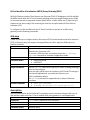
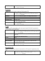
dcb-map
Create a DCB map to configure priority flow control (PFC) and enhanced transmission selection
(ETS) on Ethernet ports that support converged Ethernet traffic. Apply the DCB map to an
Ethernet interface.
dcb-map map-name
Syntax
Parameters
map-name = Enter a DCB map name. The maximum number of
alphanumeric characters is 32.
To remove a DCB map from an interface, enter the no dcb-map
map-name command in Interface Configuration mode.
Defaults
None.
Command Modes
• CONFIGURATION
• INTERFACE
Command History
Version 9.3(0.0)
Usage Information
Use the dcb-map command to specify PFC and ETS settings and apply
them to Ethernet ports.
After you apply a DCB map to an interface, the PFC and ETS settings in
the map are applied when you enable the Ethernet port.
DCBx is enabled by default.
The dcb-map command is supported only on physical Ethernet
interfaces.
Related Commands
• show qos dcb-map
• dcb-map stack-unit all stack-ports all
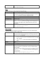
description
Add a text description of the FCoE and FC parameters used to transmit storage traffic over an
IOA and MXL switch with the FC Flex IO module NPIV proxy gateway in a converged fabric.
description text
Syntax
Parameters
text = Enter a maximum of 32 characters.
Defaults
None
Command Modes
FCOE MAP
Command History
Version 9.3(0.0)
Related Commands
•
•
fcoe-map
show fcoe-map
fabric
Apply an FCoE map on a fabric-facing Fibre Channel (FC) port.
Fabric map-name
Syntax
Parameters
map-name = Enter a maximum of 32 alphanumeric characters.
To remove an FCoE map from an FC interface, enter the no fabric
map-name command in Interface Configuration mode.
Defaults
None
Command Modes
INTERFACE FIBRE_CHANNEL
Command History
Version 9.3(0.0)
Usage Information
After you apply an FCoE map on an FC interface, when you enable the
port (no shutdown), the FC port will login to the FC equipment it is
connected to; after login success, advertisements are sent to the
server ports.
Related Commands
• fcoe-map
• interface fibrechannel
• show fcoe-map
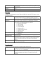
fabric-id vlan
Configure the association between the dedicated VLAN (used to carry FCoE traffic between
servers and a SAN) and the fabric storage arrays.
fabric-id fabric-num vlan vlan-id
Syntax
To remove a fabric-VLAN association from an FCoE map, enter the no
fabric-id vlan command.
Parameters
• fabric-id fabric-num = Enter a fabric ID number that is
the same as the ID number of the dedicated VLAN. The range is
from 1 to 4094.
• vlan vlan-id = Enter the ID number of the dedicated
VLAN.
Defaults
None
Command Modes
FCOE MAP
Command History
Version 9.3(0.0)
Usage Information
The fabric and VLAN ID numbers must be the same. However, in each
FCoE map, the fabric ID, FC-MAP value, and FCoE VLAN parameters
must be unique.
You must first create a VLAN and then specify the configured VLAN ID
in the fabric-id vlan command. Otherwise, the following error
message displays:
FTOS(conf-fcoe-f)#fabric-id 10 vlan 10
% Error: Vlan 10 does not exist
Related Commands
•
•
fcoe-map
show fcoe-map
fcf-priority
Configure the priority to select an upstream FCoE forwarder (FCF).
fcf—priority priority
Syntax
To remove a configured FCF priority from an FCoE map, enter the no
fcf-priority command.
Parameters
priority = Enter the fcf priority. The range is from 0 to 128.
Defaults
128
Command Modes
FCOE MAP
Command History
Version 9.3(0.0)
Usage Information
The FCF priority is used by the server CNAs to select an upstream FCF
to use for a fabric login (FLOGI).
Related Commands
• fcoe-map
• show fcoe-map
fc-map
Configure the FCoE mapped address prefix value used to identify FCoE traffic transmitted on
the FCoE VLAN for the specified fabric.
fc—map fc-map-value
Syntax
To remove a configured FC-MAP value from an FCoE map, enter the
no fc-map command.
Parameters
fc-map-value = Enter the unique MAC address prefix used by a
SAN fabric.
The range is from 0EFC00 to 0EFCFF.
Defaults
None
Command Modes
FCOE MAP
Command History
Version 9.3(0.0)
Usage Information
In an FCoE map, the FC-MAP value, fabric ID, and FCoE VLAN
parameters must be unique.
Related Commands
• fcoe-map
• show fcoe-map
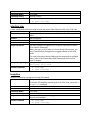
fcoe priority-bits
Configure the administrative values for advertised for the FCoE protocol in application priority
TLVs.
fcoe priority-bits priority-bitmap
Syntax
To remove the configured FCoE priority, use the no fcoe
priority-bits command.
Parameters
Defaults
Command Modes
Command History
priority-bitmap = Enter the priority-bitmap range. The range
is from 1 to FF.
0x8
PROTOCOL LLDP
Version 9.3(0.0)
fcoe-map
Configure the links between the server CNAs and a SAN fabric. Apply the FCoE map on a serverfacing Ethernet port.
fcoe-map map-name
Syntax
To remove an FCoE map from an Ethernet interface, enter the no
fcoe-map map-name command in Interface configuration mode.
Parameters
map-name = Enter a maximum of 32 alphanumeric characters.
Defaults
None for the MXL switch.
For the IOA, the following parameters are applied:
• Description: SAN_FABRIC
• Fabric-id: 1002
• Fcoe-vlan: 1002
• Fc-map: 0x0efc00
• Fcf-priority: 128
• Fka-adv-period: 8000mSec
• Keepalive: enable
• Vlan priority: 3
Command Modes
• CONFIGURATION
• INTERFACE
Command History
Version 9.3(0.0)
Usage Information
In each FCoE map, the fabric ID, FC-MAP value, and FCoE VLAN
parameters must be unique. Use one FCoE map to access one SAN
fabric. You cannot use the same FCoE map to access different
fabrics.
Related Commands
• interface fibrechannel
• show fcoe-map
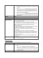
fka-adv-period
Configure the time used to transmit FIP keepalive (FKA) advertisements.
fka-adv-period seconds
Syntax
To delete the FIP keepalive time period from an FCoE map, enter the
no fka-adv-period command.
Parameters
Seconds = Enter the time period (in seconds) used to send FIP
keepalive messages to peer devices. The range is from 8 to 90
seconds.
Defaults
Command Modes
Command History
Related Commands
8 seconds
FCOE MAP
Version 9.3(0.0)
• fcoe-map
• show fcoe-map
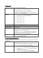
interface vlan
Create a dedicated VLAN to be used to send and receive Fibre Channel traffic over FCoE links.
interface vlan vlan-id
Syntax
Parameters
vlan-id = Enter a number as the VLAN Identifier. The range is 1 to
4094.
Defaults
Not configured.
Command Modes
CONFIGURATION
Command History
Version 9.3(0.0)
Usage Information
You must configure a separate FCoE VLAN for each fabric to which
FCoE traffic is forwarded.
When you apply an FCoE map to a server-facing Ethernet port, the
port is automatically configured as a tagged member of the FCoE
VLAN.
For more information about VLANs and the commands to configure
them, refer to the Virtual LAN (VLAN) Commands section of the
Layer 2 chapter.
Example (Single Range) Dell(conf)#interface vlan 10
Dell(conf-if-vl-10)#
Related Commands
• fcoe-map
• show fcoe-map
keepalive
Enable FIP keepalive message monitoring (if disabled).
Keepalive
Syntax
To remove FIP keepalive monitoring from an FCoE map, enter the no
keepalive command.
Parameters
None
Defaults
Enabled on Ethernet and FC interfaces.
Command Modes
FCOE MAP
Command History
Version 9.3(0.0)
Usage Information
Use FIP keepalive (FKA) messaging to detect if the other FCoE
devices are reachable.
Related Command
• fcoe-map
• show fcoe-map
Priority-pgid
Assign 802.1 priority traffic to a priority group in a DCB map.
priority-pgid dot1p0_group-num dot1p1_groupSyntax
num dot1p2_group-num dot1p3_group-num
dot1p4_group-num dot1p5_group-num
dot1p6_group-num dot1p7_group-num
To remove a priority-pgid configuration from a DCB map, enter the
no priority-pgid command.
Parameters
• dotp0_group-num = Enter the priority group number for
each 802.1p class of traffic in a DCB map.
• dotp1_group-num
• dotp2_group-num
• dotp3_group-num
• dotp4_group-num
• dotp5_group-num
• dotp6_group-num
• dotp7_group-num
Defaults
None
Command Modes
DCB MAP
Command History
Version 9.3(0.0)
Usage Information
PFC and ETS settings are not pre-configured on Ethernet ports. You
must use the dcb-map command to configure different groups of
802.1p priorities with PFC and ETS settings.
Using the priority-pgid command, you assign each 802.1p
priority to one priority group. All 802.1p priorities mapped to the
same queue must be in the same priority group.
Related Command
• dcb-map
• priority-group bandwidth pfc
priority-group bandwidth pfc
Configure the ETS bandwidth allocation and PFC mode used to manage port traffic in an 802.1p
priority group.
priority-group group-num {bandwidth
Syntax
percentage| strict-priority} pfc {on | off}
To remove a priority-group configuration in a DCB map, enter the no
priority-group bandwidth pfc command.
Parameters
• priority-group group-num = Enter the keyword
priority-group then the number of an 802.1p priority
group. Use the priority-pgid command to create the
priority groups in a DCB map.
• bandwidth percentage = Enter the keyword
bandwidth then a bandwidth percentage allocated to the
•
•
Defaults
Command Modes
Command History
Usage Information
Related Command
priority group. The range is 1 to 100. The sum of all allocated
bandwidth percentages in priority groups in a DCB map must
be 100%.
strict-priority = Configure the priority-group traffic
to be handled with strict priority scheduling. Strict-priority
traffic is serviced first, before bandwidth allocated to other
priority groups is made available.
pfc {on | off} = Configure whether priority-based flow
control is enabled (on) or disabled (off) for port traffic in the
priority group.
None
DCB MAP
Version 9.3(0.0)
Use this command to configure PFC and ETS traffic handling for each
priority group in a DCB map.
You can enable PFC on a maximum of two priority queues.
If you configure more than one priority group as strict priority, the
higher numbered priority queue is given preference when
scheduling data traffic.
If a priority group does not use its allocated bandwidth, the unused
bandwidth is made available to other priority groups.
By default, equal bandwidth is assigned to each dot1p priority in a
priority group.
Use the bandwidth parameter to configure the bandwidth
percentage assigned to a priority group. The sum of the bandwidth
allocated to all priority groups in a DCB map must be 100% of the
bandwidth on the link.
You must allocate at least 1% of the total port bandwidth to each
priority group.
• dcb-map
• priority-pgid
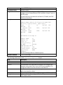
show fcoe-map
Display the Fibre Channel and FCoE configuration parameters in FCoE maps.
show fcoe-map [brief | map-name]
Syntax
Parameters
• brief = Displays an overview of currently configured FCoE
maps.
• map-name = Displays the FC and FCoE configuration
parameters in a specified FCoE map. The FCoE map is applied
on Ethernet (FCoE) and FC ports to transmit FC storage traffic
to a specified fabric.
Command Modes
• EXEC
Command History
Usage Information
Example
• EXEC Privilege
Version 9.3(0.0)
Use this command to display the FC and FCoE parameters used to
configure server-facing Ethernet (FCoE) and fabric-facing FC ports in
all FCoE maps.
In each FCoE map, the values for the fabric ID, FC-MAP, and FCoE
VLAN must be unique.
Dell#show fcoe-map brief
Fabric-Name Fabric-Id Vlan-Id FC-MAP FCFPriority Config-State Oper-State
test
16
16
0efc02 128
ACTIVE
UP
cnatest 1003
1003
0efc03 128
ACTIVE
UP
Sitest 1004
1004
0efc04 128
ACTIVE
DOWN
Dell#show fcoe-map si
Related Command
Fabric Name
si
Fabric Id
1004
Vlan Id
1004
Vlan priority 3
FC-MAP
0efc04
FKA-ADV-Period 8
Fcf Priority
128
Config-State
ACTIVE
Oper-State
DOWN
Members
See the following tables for field descriptions.
• fcoe-map
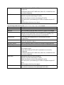
The following table describes the show fcoe-map brief output.
Field
Description
Field-Name
Name of a SAN fabric.
Fabric ID
The ID number of the SAN fabric to which FC traffic is forwarded.
VLAN ID
The dedicated FCoE VLAN used to transport FCoE storage traffic
between servers and a fabric over the NPIV proxy gateway. The
configured VLAN ID must be the same as the fabric ID.
FC-MAP
FCoE MAC address-prefix value - The unique 24-bit MAC address
prefix that identifies a fabric.
FCF Priority
The priority used by a server to select an upstream FCoE forwarder.
Config-State
Indicates whether the configured FCoE and FC parameters in the
FCoE map are valid:
Oper-State
Active (all mandatory FCoE and FC parameters are correctly
configured)
Incomplete (either the FC-MAP value, fabric ID, or VLAN ID are not
correctly configured).
Operational status of link to the fabric:
Up (link is up and transmitting FC traffic)
Down (link is down and not transmitting FC traffic)
Link-wait (link is up and waiting for FLOGI to complete on peer FC
port)
Removed (port has been shut down).
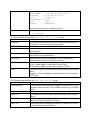
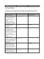
The following table describes the show fcoe-map map-name output.
Field
Description
Fabric-Name
Name of a SAN fabric.
Fabric ID
The ID number of the SAN fabric to which FC traffic is forwarded.
VLAN ID
The dedicated FCoE VLAN used to transport FCoE storage traffic
between servers and a fabric over the NPIV proxy gateway. The
configured VLAN ID must be the same as the fabric ID.
VLAN priority
FCoE traffic uses VLAN priority 3. (This setting is not userconfigurable.)
FC-MAP
FCoE MAC address-prefix value - The unique 24-bit MAC address
prefix that identifies a fabric.
FKA-ADV_period
Time (in seconds) used to transmit FIP keepalive advertisements.
FCF Priority
The priority used by a server to select an upstream FCoE forwarder.
Config-State
Indicates whether the configured FCoE and FC parameters in the
FCoE map are valid:
Active (all mandatory FCoE and FC parameters are correctly
configured)
Incomplete (either the FC-MAP value, fabric ID, or VLAN ID are not
correctly configured).
Oper-State
Operational status of link to the fabric:
Up (link is up and transmitting FC traffic)
Down (link is down and not transmitting FC traffic)
Link-wait (link is up and waiting for FLOGI to complete on peer FC
port)
Removed (port has been shut down).
Members
IOA and MXL Switch with the FC Flex IO module Ethernet and FC
ports that are members of the dedicated FCoE VLAN.
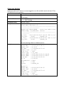
show npiv devices
Display the FCoE and FC devices currently logged in to an IOA and MXL switch with the FC Flex
IO module NPIV proxy gateway.
show npiv devices [brief]
Syntax
Parameters
Brief = Displays an overview of current server CNA-fabric
connections.
Command Modes
• EXEC
• EXEC Privilege
Command History
Version 9.3(0.0)
dell# show npiv devices brief
Example
Total NPIV Devices = 2
--------------------------------------------------------------------ENode-Intf ENode-WWPN
FCoE-Vlan Fabric-Intf
Fabric-Map LoginMethod Status
-------------------------------------------------------Te 0/12
20:01:00:10:18:f1:94:20 1003 Fc 0/5
fid_1003
FLOGI
LOGGED_IN
Te 0/13
10:00:00:00:c9:d9:9c:cb 1003 Fc 0/0
fid_1003
FDISC
LOGGED_IN
Example
See the following tables for field descriptions.
ENode[0]:
ENode MAC
: 00:10:18:f1:94:21
ENode Intf : Te 0/12
FCF MAC
: 5c:f9:dd:ef:10:c8
Fabric Intf : Fc 0/5
FCoE Vlan
: 1003
Fabric Map : fid_1003
ENode WWPN : 20:01:00:10:18:f1:94:20
ENode WWNN : 20:00:00:10:18:f1:94:21
FCoE MAC
: 0e:fc:03:01:02:01
FC-ID
: 01:02:01
LoginMethod : FLOGI
Secs
: 5593
Status
: LOGGED_IN
ENode[1]:
ENode MAC
ENode Intf
FCF MAC
Fabric Intf
FCoE Vlan
Fabric Map
:
:
:
:
:
:
00:10:18:f1:94:22
Te 0/13
5c:f9:dd:ef:10:c9
Fc 0/0
1003
fid_1003
ENode WWPN
ENode WWNN
FCoE MAC
FC-ID
LoginMethod
Secs
Status
Related Command
:
:
:
:
:
:
:
10:00:00:00:c9:d9:9c:cb
10:00:00:00:c9:d9:9c:cd
0e:fc:03:01:02:02
01:02:01
FDISC
5593
LOGGED_IN
See the following tables for field descriptions.
• dcb-map
• fcoe-map
The following table describes the show npiv devices brief output.
Field
Description
ENode-Intf
IOA and MXL switch with the FC Flex IO module Ethernet interface
(slot/port) to which a server CNA is connected.
ENode-WWPN
Worldwide port name (WWPN) of a server CNA port.
FCoE-Vlan
VLAN ID of the dedicated VLAN used to transmit FCoE traffic to and
from the fabric.
Fabric_Intf
Fabric-facing Fibre Channel port (slot/port) on which FC traffic is
transmitted to the specified fabric.
Fabric-Map
Name of the FCoE map containing the FCoE/FC configuration
parameters for the server CNA-fabric connection.
LoginMethod
Method used by the server CNA to log in to the fabric; for example:
FLOGI - ENode logged in using a fabric login (FLOGI).
FDISC - ENode logged in using a fabric discovery (FDISC).
Status
Operational status of the link between a server CNA port and a SAN
fabric:
Logged In - Server has logged in to the fabric and is able to transmit
FCoE traffic.
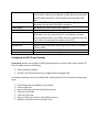
The following table describes the show npiv devices output.
Field
Description
ENode [number]
A server CNA that has successfully logged in to a fabric over an IOA
and MXL switch with the FC Flex IO module Ethernet port in ENode
mode.
Enode MAC
MAC address of a server CNA port.
Enode Intf
Port number of a server-facing Ethernet port operating in ENode
mode.
FCF MAC
Fibre Channel forwarder MAC: MAC address of IOA and MXL switch
with the FC Flex IO module FCF interface.
Fabric Intf
Fabric-facing Fibre Channel port (slot/port) on which FCoE traffic is
transmitted to the specified fabric.
FCoE VLAN
Fabric Map
Enode WWPN
Enode WWNN
FCoE MAC
FC-ID
LoginMethod
Secs
State
ID of the dedicated VLAN used to transmit FCoE traffic from a
server CNA to a fabric and configured on both the server-facing IOA
and MXL switch with the FC Flex IO module port and server CNA
port.
Name of the FCoE map containing the FCoE/FC configuration
parameters for the server CNA-fabric connection.
Worldwide port name of the server CNA port.
Worldwide node name of the server CNA.
Fabric-provided MAC address (FPMA). The FPMA consists of the FCMAP value in the FCoE map and the FC-ID provided by the fabric
after a successful FLOGI. In the FPMA, the most significant bytes are
the FC-MAP; the least significant bytes are the FC-ID.
FC port ID provided by the fabric.
Method used by the server CNA to log in to the fabric; for example,
FLOGI or FDISC.
Number of seconds that the fabric connection is up.
Status of the fabric connection: logged in.
Configuring an NPIV Proxy Gateway
Prerequisite: Before you configure an NPIV proxy gateway on an IOA or MXL switch with the FC
Flex IO module, ensure the following:
•
•
DCB is enabled by default.
DCB (PFC and ETS) parameters are configured for converged traffic.
To configure NPG operation on an IOA and MXL switch with the FC Flex IO module, follow these
steps:
1.
2.
3.
4.
5.
6.
7.
Enable Fibre Channel capability on the switch.
Create a DCB map.
Apply a DCB map on server-facing Ethernet ports.
Create an FCoE VLAN.
Create an FCoE map.
Apply an FCoE map on server-facing Ethernet ports.
Apply an FCoE Map on fabric-facing FC ports.
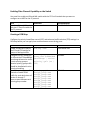
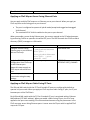
Enabling Fibre Channel Capability on the Switch
You must first enable an IOA and MXL switch with the FC Flex IO module that you want to
configure as an NPG for the FC protocol.
Task
Command
Enable an IOA and MXL switch feature fc
with the FC Flex IO module for
the FC protocol.
Command Mode
CONFIGURATION
Creating a DCB Map
Configure the priority-based flow control (PFC) and enhanced traffic selection (ETS) settings in a
DCB map before you can apply them on downstream server-facing ports.
Task
Create a DCB map to specify
the PFC and ETS settings for
groups of dot1p priorities.
Configure the PFC setting (on
or off) and the ETS bandwidth
percentage allocated to traffic
in each priority group or
whether priority group traffic
should be handled with strict
priority scheduling.
Specify the priority group ID
number to handle VLAN
traffic for each dot1p class-ofservice: 0 through 7.
Leave a space between each
priority group number.
Command
dcb-map name
Command Mode
CONFIGURATION
priority-group
group_num {bandwidth
percentage | strictpriority} pfc {on |
off}
DCB MAP
priority-pgid
dot1p0_group-num
dot1p1_group-num
dot1p2_group-num
dot1p3_group-num
dot1p4_group-num
dot1p5_group-num
dot1p6_group-num
dot1p7_group-num
DCB MAP
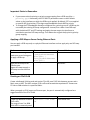
Important Points to Remember
•
•
If you remove a dot1p priority-to-priority group mapping from a DCB map (the no
priority pgid command), the PFC and ETS parameters revert to their default
values on the interfaces on which the DCB map is applied. By default, PFC is not applied
on specific 802.1p priorities; ETS assigns equal bandwidth to each 802.1p priority.
To change the ETS bandwidth allocation configured for a priority group in a DCB map, do
not modify the existing DCB map configuration. Instead, first create a new DCB map
with the desired PFC and ETS settings and apply the new map to the interfaces to
override the previous DCB map settings. Then delete the original dot1p priority-priority
group mapping.
Applying a DCB Map on Server-Facing Ethernet Ports
You can apply a DCB map only on a physical Ethernet interface and can apply only one DCB map
per interface.
Task
Enter Interface Configuration
mode on a server-facing port
to apply a DCB map.
Apply the DCB map on an
Ethernet port.
Repeat this step to apply a
DCB map to more than one
port.
Command
interface
{tengigabitEthernet
slot/port |
fortygigabitEthernet
slot/port}
dcb-map name
Command Mode
CONFIGURATION
INTERFACE
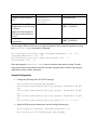
Creating an FCoE VLAN
Create a dedicated VLAN to send and receive FC traffic over FCoE links between servers and a
fabric over an NPG. The NPG receives FCoE traffic and forwards de-capsulated FC frames over
FC links to SAN switches in a specified fabric.
When you apply an FCoE map to an Ethernet port, the port is automatically configured as a
tagged member of the FCoE VLAN.
Task
Command
Create the dedicated VLAN for interface vlan vlanid
FCoE traffic.
The range is from 2 to 4094.
VLAN 1002 is commonly used
Command Mode
CONFIGURATION
to transmit FCoE traffic.
Creating an FCoE Map
The values for the FCoE VLAN, fabric ID, and FC-MAP must be unique. Apply an FCoE map on
downstream server-facing Ethernet ports and upstream fabric-facing Fibre Channel ports.
Task
Create an FCoE map.
Configure the association
between the dedicated VLAN
and the fabric where the
desired storage arrays are
installed.
The fabric and VLAN ID
numbers must be the same.
The range is from 2 to 4094.
Add a text description.
The maximum is 32
characters.
Specify the FC-MAP value
used to generate a fabricprovided MAC address.
You must enter a unique MAC
address prefix as the FC-MAP
value for each fabric.
The range is from 0EFC00 to
0EFCFF.
The default is None.
Configure the priority used by
a server CNA to select the FCF
for a fabric login (FLOGI). The
range is from 0 to 128. The
default is 128.
Enable the monitoring FIP
keepalive messages (if it is
disabled) to detect if other
FCoE devices are reachable.
The default is enabled.
Configure the time (in
seconds) used to transmit FIP
keepalive advertisements.
The range is 8 to 90 seconds.
Command
fcoe-map map-name
fabric-id fabric-num
vlan vlan-id
Command Mode
CONFIGURATION
FCoE MAP
description text
FCoE MAP
fc-map fc-map-value
FCoE MAP
fcf-priority
priority
FCoE MAP
keepalive
FCoE MAP
fka-adv-period
seconds
FCoE MAP
The default is 8 seconds.
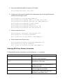
Applying an FCoE Map on Server-Facing Ethernet Ports
You can apply multiple FCoE maps on an Ethernet port or port channel. When you apply an
FCoE map on a server-facing port or port channel:
•
•
The port is configured to operate in hybrid mode (accept both tagged and untagged
VLAN frames).
The associated FCoE VLAN is enabled on the port or port channel.
When you enable a server-facing Ethernet port, the servers respond to the FIP advertisements
by performing FLOGIs on upstream virtualized FCF ports. The NPG forwards the FLOGIs as fabric
discovery (FDISC) messages to a SAN switch.
Task
Configure a server-facing
Ethernet port or port channel
with an FCoE map.
Apply the FCoE/FC
configuration in an FCoE map
on the Ethernet port.
Repeat this step to apply an
FCoE map to more than one
port.
Enable the port for FCoE
transmission using the map
settings.
Command
interface
{tengigabitEthernet
slot/port |
fortygigabitEthernet
slot/port | portchannel num}
fcoe-map map-name
Command Mode
CONFIGURATION
no shutdown
INTERFACE
INTERFACE or
INTERFACE PORT_CHANNEL
Applying an FCoE Map on Fabric-Facing FC Ports
The IOA and MXL switch with the FC Flex IO module FC ports are configured by default to
operate in N port mode. When you apply an FCoE map on a fabric-facing FC port, the FC port
becomes part of the FCoE fabric.
Each IOA and MXL switch with the FC Flex IO module FC port is associated with an Ethernet
MAC address (FCF MAC address). When you enable a fabric-facing FC port, the FCoE map
applied to the port starts sending FIP multicast advertisements using the parameters in the
FCoE map over server-facing Ethernet ports. A server sees the FC port with its applied FCoE
map as an FCF port.
Task
Configure a fabric-facing FC
port.
Command
interface
fibrechannel
slot/port
fabric map-name
Apply the FCoE and FC fabric
configurations in an FCoE map
to the port.
Repeat this step to apply an
FCoE map to more than one
FC port.
no shutdown
Enable the port for FC
transmission.
Command Mode
CONFIGURATION
INTERFACE
FIBRE_CHANNEL
INTERFACE
FIBRE_CHANNEL
You can apply a DCB or FCoE map to a range of Ethernet or Fibre Channel interfaces by using
the interface range command; for example:
Dell(config)# interface range tengigabitEthernet 1/12 - 23 ,
tengigabitEthernet 2/24 – 35
Dell(config)# interface range fibrechannel 0/0 - 3 ,
fibrechannel 0/8 – 11
Enter the keywords interface range then an interface type and port range. The port
range must contain spaces before and after the dash. Separate each interface type and port
range with a space, comma, and space.
Sample Configuration
1. Configure a DCB map with PFC and ETS settings.
Dell(config)# dcb-map SAN_DCB_MAP
Dell(config-dcbx-name)# priority-group 0 bandwidth 60 pfc
off
Dell(config-dcbx-name)# priority-group 1 bandwidth 20 pfc
on
Dell(config-dcbx-name)# priority-group 2 bandwidth 20 pfc
on
Dell(config-dcbx-name)# priority-pgid 0 0 0 1 2 0 0 0
2. Apply the DCB map on a downstream (server-facing) Ethernet port.
Dell(config)# interface tengigabitethernet 1/0
Dell(config-if-te-0/0)#dcb-map SAN_DCB_MAP
3. Create the dedicated VLAN to be used for FCoE traffic.
Dell(conf)#interface vlan 1002
4. Configure an FCoE map to be applied to the downstream (server-facing) Ethernet and
upstream (core-facing) FC ports.
Dell(config)# fcoe-map SAN_FABRIC_A
Dell(config-fcoe-name)# fabric-id 1002 vlan 1002
Dell(config-fcoe-name)# description "SAN_FABRIC_A"
Dell(config-fcoe-name)# fc-map 0efc00
Dell(config-fcoe-name)# keepalive
Dell(config-fcoe-name)# fcf-priority 128
Dell(config-fcoe-name)# fka-adv-period 8
5. Enable an upstream FC port.
Dell(config)# interface fibrechannel 0/0
Dell(config-if-fc-0)# no shutdown
Dell (config-if-fc-0)# fabric SAN_FABRIC_A
6. Enable a downstream Ethernet port.
Dell(config)#interface tengigabitEthernet 0/0
Dell(conf-if-te-0)# no shutdown
Dell (conif-if-te-0)# fcoe-map SAN_FABRIC_A
Displaying NPIV Proxy Gateway Information
To display NPG operation information, use the following show commands.
Command
Show interfaces status
show fcoe-map [brief | mapname]
show qos dcb-map map-name
show npiv devices [brief]
show fc switch
Description
Displays the operational status of Ethernet
and Fibre Channel interfaces.
Displays the FC and FCoE configuration
parameters in FCoE maps.
Displays the configuration parameters in a
specified DCB map.
Displays information on FCoE and FC devices
currently logged in to the NPG.
Displays the FC mode of operation and
worldwide node (WWN) name.
For more information about NPIV Proxy Gateway information, refer to the 9.3(0.0) Addendum.
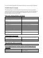
IOA PMUX Mode CLI Commands
The following tables list the IOA PMUX mode CLI commands that you can access without a
separate user profile. For more information about these commands, refer to the Addendum for
Dell Networking OS 9.3(0.0) or the PowerEdge M IO Aggregator Command Line Interface for
Dell Networking OS version 9.2(0.2)/9.2(0.0).
Data Center Bridging (DCB) CLI Commands
advertise dcbx-appln-tlv
Dcb-map
dcb stack-unit all pfcbuffering pfc-port-count pfcqueues
dcbx port-role
iscsi priority-bits
pfc mode on
pfc priority
priority-group
show interface dcbx detail
show interface pfc
Show qos dcb-map
show stack-unit stack-ports pfc
details
show stack-unit stack-ports ets
details
advertise dcbx-tlv
dcb enable
dcb stack-unit pfc-buffering
pfc-port-count pfc-queues
dcbx version
description
fcoe priority-bits
Priority-pgid
pfc no-drop queues
scheduler
show dcb
show interface ets
show interface pfc statistics
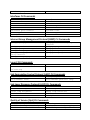
FIP Snooping CLI Commands
clear fip-snooping database
interface vlan
feature fip-snooping
fip-snooping fc-map
clear fip-snooping statistics
fip-snooping enable
fip-snooping port-mode fcf
High Availability (HA) CLI Commands
redundancy force-failover
show redundancy
Internet Small Computer System Interface (iSCSI) Optimization CLI
Commands
advertise dcbx-app-tlv
iscsi cos
iscsi priority-bits
iscsi aging time
iscsi enable
iscsi profile-compellant
iscsi target port
Interfaces CLI Commands
clear counters
flowcontrol
interface ManagementEthernet
interface vlan
negotiation auto
interface port-channel
Vlan tagged
description
interface
interface range
mtu
portmode hybrid
channel-member
minimum-links
Vlan untagged
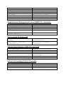
Internet Group Management Protocol (IGMP) CLI Commands
ip igmp group-join-limit
ip igmp querier-timeout
ip igmp query-max-resp-time
ip igmp snooping enable
ip igmp snooping last-memberquery-interval
ip igmp snooping querier
ip igmp last-member-queryinterval
ip igmp query-interval
ip igmp version
ip igmp snooping fast-leave
ip igmp snooping mrouter
Layer 2 CLI Commands
mac-address-table aging-time
mac-address-table station-move
refresh-arp
mac-address-table static
Link Aggregation Control Protocol (LACP) CLI Commands
lacp long-timeout
port-channel mode
lacp port-priority
port-channel-protocol lacp
Link Layer Discovery Protocol (LLDP) CLI Commands
advertise dot1-tlv
advertise management-tlv
clear lldp neighbors
disable
mode
advertise dot3-tlv
clear lldp counters
debug lldp interface
hello
multiplier
Quality of Service (QoS) CLI Commands
dot1p-priority
service-class dynamic dot1p
service-class bandwidth-
rate shape
service-class dot1p-mapping
bandwidth-percentage
percentage
clear qos statistics
policy-aggregate
qos-policy-output
rate shape
service-queue
show qos policy-map
wred-profile
description
policy-map-output
rate police
service-policy output
set
wred
Simple Network Management Protocol (SNMP) CLI Commands
snmp-server enable traps
clear logging
logging buffered
logging monitor
show logging
snmp-server host
logging
logging console
logging source-interface
show logging driverlog stackunit
terminal monitor
Storm Control CLI Commands
show storm-control unknownunicast
storm-control multicast
(Configuration)
storm-control broadcast
(Configuration)
storm-control broadcast
(Interface)
Uplink Failure Detection (UFD) CLI Commands
clear ufd-disable
description
downstream auto-recover
enable
show uplink-state-group
upstream
debug uplink-state-group
downstream
downstream disable links
show running-config uplinkstate-group
uplink-state-group
Virtual Link Trunking (VLT) CLI Commands
back-up destination
peer-link port-channel
show vlt mismatch
vlt domain
clear vlt statistics
lacp ungroup member-independent
unit-id
vlt-peer-lag port-channel