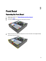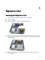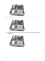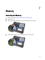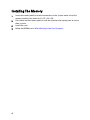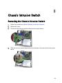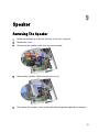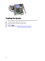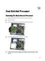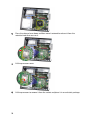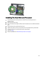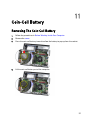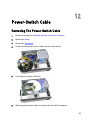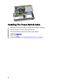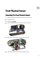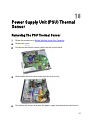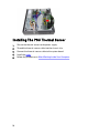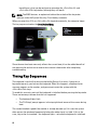
1
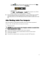
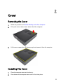
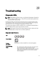
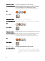
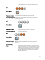
Dell OptiPlex 790 Desktop Owner's Manual
Regulatory Model: D05D
Regulatory Type: D05D001
Notes, Cautions, and Warnings
NOTE: A NOTE indicates important information that helps you make better use of your
computer.
CAUTION: A CAUTION indicates potential damage to hardware or loss of data if
instructions are not followed.
WARNING: A WARNING indicates a potential for property damage, personal injury, or
death.
Information in this publication is subject to change without notice.
© 2011 Dell Inc. All rights reserved.
Reproduction of these materials in any manner whatsoever without the written permission of Dell Inc. is
strictly forbidden.
Trademarks used in this text: Dell™, the DELL logo, Dell Precision™, Precision ON™,ExpressCharge™,
Latitude™, Latitude ON™, OptiPlex™, Vostro™, and Wi-Fi Catcher™ are trademarks of Dell Inc. Intel®,
Pentium®, Xeon®, Core™, Atom™, Centrino®, and Celeron® are registered trademarks or trademarks of Intel
Corporation in the U.S. and other countries. AMD® is a registered trademark and AMD Opteron™,
AMD Phenom™, AMD Sempron™, AMD Athlon™, ATI Radeon™, and ATI FirePro™ are trademarks of
Advanced Micro Devices, Inc. Microsoft®, Windows®, MS-DOS®, Windows Vista®, the Windows Vista start
button, and Office Outlook® are either trademarks or registered trademarks of Microsoft Corporation in the
United States and/or other countries. Blu-ray Disc™ is a trademark owned by the Blu-ray Disc Association
(BDA) and licensed for use on discs and players. The Bluetooth® word mark is a registered trademark and
owned by the Bluetooth® SIG, Inc. and any use of such mark by Dell Inc. is under license. Wi-Fi® is a
registered trademark of Wireless Ethernet Compatibility Alliance, Inc.
Other trademarks and trade names may be used in this publication to refer to either the entities claiming the
marks and names or their products, Dell Inc. disclaims any proprietary interest in trademarks and trade
names other than its own.
2011 — 07
Rev. A00
Contents
Notes, Cautions, and Warnings..................................................................2
1 Working on Your Computer......................................................................9
Before Working Inside Your Computer.............................................................................9
Recommended Tools.......................................................................................................10
Turning Off Your Computer..............................................................................................10
After Working Inside Your Computer..............................................................................11
2 Cover..........................................................................................................13
Removing the Cover........................................................................................................13
Installing The Cover.........................................................................................................13
3 Front Bezel.................................................................................................15
Removing the Front Bezel................................................................................................15
Installing The Front Bezel................................................................................................16
4 Expansion Card.........................................................................................17
Removing the Expansion Card.........................................................................................17
Installing The Expansion Card.........................................................................................19
5 Optical Drive..............................................................................................21
Removing the Optical Drive.............................................................................................21
Installing The Optical Drive.............................................................................................22
6 Hard Drive..................................................................................................23
Removing the Hard Drive................................................................................................23
Installing The Hard Drive.................................................................................................25
7 Memory......................................................................................................27
Removing the Memory....................................................................................................27
Installing The Memory.....................................................................................................28
8 Chassis Intrusion Switch........................................................................29
Removing the Chassis Intrusion Switch..........................................................................29
Installing The Chassis Intrusion Switch..........................................................................30
9 Speaker......................................................................................................31
Removing The Speaker...................................................................................................31
Installing The Speaker.....................................................................................................32
10 Heat Sink And Processor......................................................................33
Removing The Heat Sink and Processor.........................................................................33
Installing The Heat Sink and Processor..........................................................................35
11 Coin-Cell Battery....................................................................................37
Removing The Coin-Cell Battery.....................................................................................37
Installing The Coin-Cell Battery.......................................................................................38
12 Power-Switch Cable..............................................................................39
Removing The Power-Switch Cable................................................................................39
Installing The Power-Switch Cable.................................................................................40
13 Front Thermal Sensor............................................................................41
Removing The Front Thermal Sensor..............................................................................41
Installing The Front Thermal Sensor...............................................................................42
14 System Fan..............................................................................................43
Removing The System Fan..............................................................................................43
Installing The System Fan...............................................................................................44
15 Input/Output Panel.................................................................................47
Removing The Input/Output Panel..................................................................................47
Installing The Input/Output Panel....................................................................................48
16 Power Supply..........................................................................................49
Removing The Power Supply..........................................................................................49
Installing The Power Supply...........................................................................................51
17 System Board..........................................................................................53
Removing The System Board..........................................................................................53
Installing The System Board...........................................................................................54
18 Power Supply Unit (PSU) Thermal Sensor.........................................57
Removing The PSU Thermal Sensor...............................................................................57
Installing The PSU Thermal Sensor................................................................................58
19 System Setup..........................................................................................59
System Setup..................................................................................................................59
Boot Menu.......................................................................................................................59
Boot Menu Enhancements..............................................................................................59
Timing Key Sequences....................................................................................................60
Navigation.......................................................................................................................61
System Setup Options.....................................................................................................61
20 Troubleshooting......................................................................................71
Diagnostic LEDs..............................................................................................................71
Diagnostic Light Patterns..........................................................................................71
Beep Codes.....................................................................................................................78
Error Messages...............................................................................................................81
Address mark not found............................................................................................81
Alert! Previous attempts at booting this system have failed at checkpoint
[nnnn]. For help in resolving this problem, please note this checkpoint and
contact Dell Technical Support................................................................................81
Alert! Security override Jumper is installed.............................................................82
Attachment failed to respond...................................................................................82
Bad command or file name ......................................................................................82
Bad error-correction code (ECC) on disk read.........................................................82
Controller has failed..................................................................................................82
Data error .................................................................................................................82
Decreasing available memory .................................................................................83
Diskette drive 0 seek failure.....................................................................................83
Diskette read failure.................................................................................................83
Diskette subsystem reset failed................................................................................83
Gate A20 failure........................................................................................................83
General failure .........................................................................................................83
Hard-disk drive configuration error .........................................................................83
Hard-disk drive controller failure..............................................................................84
Hard-disk drive failure .............................................................................................84
Hard-disk drive read failure......................................................................................84
Invalid configuration information-please run SETUP program.................................84
Invalid Memory configuration, please populate DIMM1..........................................84
Keyboard failure.......................................................................................................84
Memory address line failure at address, read value expecting value ....................84
Memory allocation error...........................................................................................85
Memory data line failure at address, read value expecting value...........................85
Memory double word logic failure at address, read value expecting value............85
Memory odd/even logic failure at address, read value expecting value.................85
Memory write/read failure at address, read value expecting value........................85
Memory size in CMOS invalid...................................................................................85
Memory tests terminated by keystroke....................................................................86
No boot device available..........................................................................................86
No boot sector on hard-disk drive............................................................................86
No timer tick interrupt ..............................................................................................86
Non-system disk or disk error...................................................................................86
Not a boot diskette....................................................................................................86
Plug and play configuration error.............................................................................86
Read fault..................................................................................................................87
Requested sector not found.....................................................................................87
Reset failed...............................................................................................................87
Sector not found ......................................................................................................87
Seek error ................................................................................................................87
Shutdown failure ......................................................................................................87
Time-of-day clock stopped ......................................................................................87
Time-of-day not set-please run the System Setup program ...................................88
Timer chip counter 2 failed ......................................................................................88
Unexpected interrupt in protected mode.................................................................88
WARNING: Dell's Disk Monitoring System has detected that drive [0/1] on the
[primary/secondary] EIDE controller is operating outside of normal
specifications. It is advisable to immediately back up your data and replace
your hard drive by calling your support desk or Dell................................................88
Write fault.................................................................................................................88
Write fault on selected drive....................................................................................89
X:\ is not accessible. The device is not ready ..........................................................89
21 Specifications.........................................................................................91
Technical Specifications.................................................................................................91
22 Contacting Dell.....................................................................................101
Contacting Dell..............................................................................................................101
8
Working on Your Computer
1
Before Working Inside Your Computer
Use the following safety guidelines to help protect your computer from potential damage
and to help to ensure your personal safety. Unless otherwise noted, each procedure
included in this document assumes that the following conditions exist:
•
•
You have read the safety information that shipped with your computer.
A component can be replaced or--if purchased separately--installed by
performing the removal procedure in reverse order.
WARNING: Before working inside your computer, read the safety information that
shipped with your computer. For additional safety best practices information, see
the Regulatory Compliance Homepage at www.dell.com/regulatory_compliance.
CAUTION: Many repairs may only be done by a certified service technician. You
should only perform troubleshooting and simple repairs as authorized in your
product documentation, or as directed by the online or telephone service and
support team. Damage due to servicing that is not authorized by Dell is not covered
by your warranty. Read and follow the safety instructions that came with the
product.
CAUTION: To avoid electrostatic discharge, ground yourself by using a wrist
grounding strap or by periodically touching an unpainted metal surface, such as a
connector on the back of the computer.
CAUTION: Handle components and cards with care. Do not touch the components
or contacts on a card. Hold a card by its edges or by its metal mounting bracket.
Hold a component such as a processor by its edges, not by its pins.
CAUTION: When you disconnect a cable, pull on its connector or on its pull-tab, not
on the cable itself. Some cables have connectors with locking tabs; if you are
disconnecting this type of cable, press in on the locking tabs before you disconnect
the cable. As you pull connectors apart, keep them evenly aligned to avoid bending
any connector pins. Also, before you connect a cable, ensure that both connectors
are correctly oriented and aligned.
9
NOTE: The color of your computer and certain components may appear differently
than shown in this document.
To avoid damaging your computer, perform the following steps before you begin working
inside the computer.
1.
Ensure that your work surface is flat and clean to prevent the computer cover from
being scratched.
2.
Turn off your computer (see Turning Off Your Computer).
CAUTION: To disconnect a network cable, first unplug the cable from your
computer and then unplug the cable from the network device.
3.
Disconnect all network cables from the computer.
4.
Disconnect your computer and all attached devices from their electrical outlets.
5.
Press and hold the power button while the computer is unplugged to ground the
system board.
6.
Remove the cover.
CAUTION: Before touching anything inside your computer, ground yourself by
touching an unpainted metal surface, such as the metal at the back of the
computer. While you work, periodically touch an unpainted metal surface to
dissipate static electricity, which could harm internal components.
Recommended Tools
The procedures in this document may require the following tools:
•
Small flat-blade screwdriver
•
Phillips screwdriver
•
Small plastic scribe
•
Flash BIOS update program media
Turning Off Your Computer
CAUTION: To avoid losing data, save and close all open files and exit all open
programs before you turn off your computer.
1.
Shut down the operating system:
–
In Windows 7:
Click Start
–
10
, then click Shut Down.
In Windows Vista:
Click Start
, then click the arrow in the lower-right corner of the Start
menu as shown below, and then click Shut Down.
–
In Windows XP:
Click Start → Turn Off Computer → Turn Off . The computer turns off after
the operating system shutdown process is complete.
2.
Ensure that the computer and all attached devices are turned off. If your computer
and attached devices did not automatically turn off when you shut down your
operating system, press and hold the power button for about 6 seconds to turn them
off.
After Working Inside Your Computer
After you complete any replacement procedure, ensure you connect any external
devices, cards, and cables before turning on your computer.
1.
Replace the cover.
CAUTION: To connect a network cable, first plug the cable into the network device
and then plug it into the computer.
2.
Connect any telephone or network cables to your computer.
3.
Connect your computer and all attached devices to their electrical outlets.
4.
Turn on your computer.
5.
Verify that the computer works correctly by running the Dell Diagnostics.
11
12
Cover
2
Removing the Cover
1.
Follow the procedures in Before Working Inside Your Computer.
2.
Pull up the cover-release latch at the side of the computer.
3.
Lift the cover upward to a 45–degree angle and remove it from the computer.
Installing The Cover
1.
Place the computer cover on the chassis.
2.
Press down on the computer cover until it clicks into place.
13
3.
14
Follow the procedures in After Working Inside Your Computer.
Front Bezel
3
Removing the Front Bezel
1.
Follow the procedures in Before Working Inside Your Computer.
2.
Remove the cover.
3.
Pry the front bezel retention clips away from the chassis.
4.
Rotate the bezel away from the computer to release the hooks on the opposite edge
of the bezel from the chassis.
15
Installing The Front Bezel
1.
Insert the hooks along the bottom edge of the front bezel into the slots on the
chassis front.
2.
Rotate the bezel towards the computer to engage the four front-bezel retention clips
until they click into place.
3.
Install the cover.
4.
Follow the procedures in After Working Inside Your Computer.
16
Expansion Card
4
Removing the Expansion Card
1.
Follow the procedures in Before Working Inside Your Computer.
2.
Remove the cover.
3.
Rotate the release tab on the card-retention latch upward.
4.
Pull the release lever away from the PCIe x16 card to release the securing tab from
the dent in the card. Then, ease the card up and out of its connector and remove it
from the computer.
5.
Lift the PCIe x1 expansion card (if any) up and out of its connector and remove it
from the computer.
17
6.
Lift the PCI expansion card (if any) up and out of its connector and remove it from
the computer.
7.
Lift the PCI x4 expansion card (if any) up and out of its connector and remove it from
the computer.
18
Installing The Expansion Card
1.
Insert the PCIe x4 card into the connector on the system board and press down to
secure it in place.
2.
Insert the PCIe card (if any) into the connector on the system board and press down
to secure it in place.
3.
Insert the PCIe x1 card (if any) into the connector on the system board and press
down to secure it in place.
4.
Insert the PCIe x16 card (if any) into the connector on the system board and press
down to secure it in place.
5.
Install the cover.
6.
Follow the procedures in After Working Inside Your Computer.
19
20
Optical Drive
5
Removing the Optical Drive
1.
Follow the procedures in Before Working Inside Your Computer.
2.
Remove the cover.
3.
Remove the front bezel.
4.
Remove the data cable and power cable from the back of the optical drive.
5.
Slide up the optical-drive latch and then push the optical drive from the back
towards the front of the computer.
21
Installing The Optical Drive
1.
Slide down the optical-drive latch and push the optical drive from the front towards
the back of the computer.
2.
Connect the data cable and power cable to the optical drive.
3.
Install the front bezel.
4.
Install the cover.
5.
Follow the procedures in After Working Inside Your Computer.
22
Hard Drive
6
Removing the Hard Drive
1.
Follow the procedures in Before Working Inside Your Computer.
2.
Remove the cover.
3.
Remove the data cable and power cable from the back of the hard drive.
4.
Press the hard-drive bracket latch towards the hard drive and lift it upward.
5.
Flex the hard-drive bracket and then remove the single 3.5 inch hard drive or two 2.5
inch hard drives from the bracket.
23
6.
Turn over the hard-drive bracket and release the screws that secure the 2.5 inch
hard drive to the underside of the bracket.
7.
Flex the hard-drive bracket and then remove the two 2.5 inch hard drives from the
bracket.
8.
Release the screws that secure the 2.5 inch hard drive to the top of the hard-drive
bracket.
24
9.
Release the screws that secure the 2.5 inch hard drive to the underside of the hard
drive bracket.
Installing The Hard Drive
1.
Tighten the screws to secure the 2.5 inch hard drive(s) to the hard-drive bracket.
2.
Flex the hard-drive bracket and then insert the single 3.5 inch hard drive or the two
2.5 inch hard drives into the bracket.
3.
Press the hard-drive bracket latch towards the hard drive and insert it into the
chassis.
4.
Connect the data cable and power cable to the back of the hard drive(s).
5.
Install the cover.
6.
Follow the procedures in After Working Inside Your Computer.
25
26
Memory
7
Removing the Memory
1.
Follow the procedures in Before Working Inside Your Computer.
2.
Remove the cover.
3.
Release the memory-retention clips on each side of the memory modules.
4.
Lift the memory modules out of the connectors on the system board.
27
Installing The Memory
1.
Insert the memory modules into the connectors on the system board. Install the
memory module in the order of A1 > B1 > A2 > B2.
2.
Press down on the memory modules until the retention clips spring back to secure
them in place.
3.
Install the cover.
4.
Follow the procedures in After Working Inside Your Computer.
28
Chassis Intrusion Switch
8
Removing the Chassis Intrusion Switch
1.
Follow the procedures in Before Working Inside Your Computer.
2.
Remove the cover.
3.
Disconnect the intrusion-switch cable from the system board.
4.
Slide the intrusion switch toward the chassis bottom and remove it from the system
board.
29
Installing The Chassis Intrusion Switch
1.
Insert the intrusion switch into the chassis rear and slide it toward the chassis top
to secure it.
2.
Connect the intrusion-switch cable to the system board.
3.
Install the cover.
4.
Follow the procedures in After Working Inside Your Computer.
30
Speaker
9
Removing The Speaker
1.
Follow the procedures in Before Working Inside Your Computer.
2.
Remove the cover.
3.
Disconnect the speaker cable from the system board.
4.
Unthread the speaker cable from the chassis clip.
5.
Press down the speaker-securing tab and slide the speaker upwards to remove it.
31
Installing The Speaker
1.
Press the speaker-securing tab and slide the speaker downward to secure it.
2.
Thread the speaker cable into the chassis clip.
3.
Connect the speaker cable to the system board.
4.
Install the cover.
5.
Follow the procedures in After Working Inside Your Computer.
32
Heat Sink And Processor
10
Removing The Heat Sink and Processor
1.
Follow the procedures in Before Working Inside Your Computer.
2.
Remove the cover.
3.
Disconnect the heat-sink assembly cable from the system board.
4.
Loosen the captive screws in the order: 1, 2, 3 and 4.
5.
Lift the heat sink assembly upwards, and remove it from the computer. Lay the
assembly with the fan facing downwards, and with the thermal grease facing
upwards.
33
6.
Press the release lever down and then move it outward to release it from the
retention hook that secures it.
7.
Lift the processor cover.
8.
Lift the processor to remove it from the socket and place it in an antistatic package.
34
Installing The Heat Sink and Processor
1.
Insert the processor into the processor socket. Ensure that the processor is
properly seated.
2.
Lower the processor cover.
3.
Press the release lever down and then move it inward to secure it with the retention
hook.
4.
Place the heat sink assembly into the chassis.
5.
Tighten the captive screws to secure the heat sink assembly to the system board.
6.
Connect the heat sink assembly cable to the system board.
7.
Install the cover.
8.
Follow the procedures in After Working Inside Your Computer.
35
36
Coin-Cell Battery
11
Removing The Coin-Cell Battery
1.
Follow the procedures in Before Working Inside Your Computer.
2.
Remove the cover.
3.
Press the coin-cell battery inward to allow the battery to pop up from the socket.
4.
Lift the coin-cell battery out of the computer.
37
Installing The Coin-Cell Battery
1.
Place the coin-cell battery into its slot on the system board.
2.
Press the coin-cell battery downwards until it is secured.
3.
Install the cover.
4.
Follow the procedures in After Working Inside Your Computer.
38
Power-Switch Cable
12
Removing The Power-Switch Cable
1.
Follow the procedures in Before Working Inside Your Computer.
2.
Remove the cover.
3.
Remove the front bezel.
4.
Disconnect the power-switch cable from the system board.
5.
Pry the power-switch cable free.
6.
Slide the power-switch cable out through the front of the computer.
39
Installing The Power-Switch Cable
1.
Slide the power-switch cable in through the front of the computer.
2.
Secure the power-switch cable to the chassis.
3.
Connect the power-switch cable to the system board.
4.
Install the front bezel.
5.
Install the cover.
6.
Follow the procedures in After Working Inside Your Computer.
40
Front Thermal Sensor
13
Removing The Front Thermal Sensor
1.
Follow the procedures in Before Working Inside Your Computer.
2.
Remove the cover.
3.
Remove the front bezel.
4.
Disconnect the thermal-sensor cable from the system board.
5.
Unthread the thermal-sensor cable from the chassis clips.
6.
Unthread the thermal-sensor cable from the chassis clip.
41
7.
Pry the thermal sensor away from the chassis front and remove.
Installing The Front Thermal Sensor
1.
Secure the thermal sensor to the chassis front.
2.
Thread the thermal-sensor cable into the chassis clips.
3.
Connect the thermal-sensor cable to the system board.
4.
Install the front bezel.
5.
Install the cover.
6.
Follow the procedures in After Working Inside Your Computer.
42
System Fan
14
Removing The System Fan
1.
Follow the procedures in Before Working Inside Your Computer.
2.
Remove the cover.
3.
Remove the front bezel.
4.
Disconnect the system-fan cable from the system board.
5.
Unthread the system-fan cable from the chassis clips.
6.
Slide the four grommets inward and through the slots in the front of the computer.
43
7.
Lift and remove the system fan out of the computer.
8.
Pry up and remove the four grommets from the system fan.
Installing The System Fan
1.
Place the system fan in the chassis.
2.
Pass the four grommets through the chassis and slide outwards along the grooves
to secure them in place.
3.
Thread the system-fan cable into the chassis clips.
44
4.
Connect the system-fan cable to the system board.
5.
Install the front bezel.
6.
Install the cover.
7.
Follow the procedures in After Working Inside Your Computer.
45
46
Input/Output Panel
15
Removing The Input/Output Panel
1.
Follow the procedures in Before Working Inside Your Computer.
2.
Remove the cover.
3.
Remove the front bezel.
4.
Disconnect the Input/Output panel or the FlyWire cable from the system board.
5.
Remove the screw that secures the Input/Output panel to the chassis.
6.
Slide the Input/Output panel towards the right of the system to release from chassis.
47
7.
Remove the Input/Output panel.
Installing The Input/Output Panel
1.
Insert the Input/Output panel into the slot on the chassis front.
2.
Slide the Input/Output panel towards the left of the computer to secure to the
chassis.
3.
Tighten the screw to secure the Input/Output panel to the chassis.
4.
Connect the Input/Output panel or the FlyWire cable to the system board.
5.
Install the front bezel.
6.
Install the cover.
7.
Follow the procedures in After Working Inside Your Computer.
48
Power Supply
16
Removing The Power Supply
1.
Follow the procedures in Before Working Inside Your Computer.
2.
Remove the cover.
3.
Remove the PSU thermal sensor.
4.
Disconnect the 4–pin power cable from the system board.
5.
Unthread the 4–pin power cable from the chassis clips.
6.
Disconnect the 24–pin power cable from the system board.
49
7.
Unthread the 24–pin power cable from the chassis clip.
8.
Remove the screws that secure the power supply to the back of the computer.
9.
Push in on the blue release tab beside the power supply, and slide the power
towards the front of the computer.
50
10. Lift the power supply out of the computer.
Installing The Power Supply
1.
Place the power supply in the chassis and slide towards the back of the computer
to secure it.
2.
Tighten the screws to secure the power supply from the back of the computer.
3.
Thread the 24–pin power cable into the chassis clip.
4.
Connect the 24–pin power cable to the system board.
5.
Thread the 4–pin power cable into the chassis clips.
6.
Connect the 4–pin power cable to the system board.
7.
Install the PSU thermal sensor.
8.
Install the cover.
9.
Follow the procedures in After Working Inside Your Computer.
51
52
System Board
17
Removing The System Board
1.
Follow the procedures in Before Working Inside Your Computer.
2.
Remove the cover.
3.
Remove the front bezel.
4.
Remove the hard drive.
5.
Remove the expansion cards.
6.
Remove the heat sink and processor.
7.
Disconnect all the cables connected to the system board.
8.
Lift and release the expansion-card latch to gain access to the screws securing the
system board.
53
9.
Remove the screws that secure the system board to the chassis.
10. Slide the system board towards the front of the computer.
11. Remove the system board from the chassis.
Installing The System Board
1.
Align the system board to the port connectors on the back of the chassis and place
the system board in the chassis.
2.
Tighten the screws securing the system board to the chassis.
54
3.
Close the expansion-card latch.
4.
Connect the cables to the system board.
5.
Install the heat sink and processor.
6.
Install the expansion card.
7.
Install the hard drive.
8.
Install the front bezel.
9.
Install the cover.
10. Follow the procedures in After Working Inside Your Computer.
55
56
18
Power Supply Unit (PSU) Thermal
Sensor
Removing The PSU Thermal Sensor
1.
Follow the procedures in Before Working Inside Your Computer.
2.
Remove the cover.
3.
Disconnect the thermal-sensor cable from the system board.
4.
Unthread the thermal-sensor cable from the chassis clip.
5.
Pry the thermal sensor away from the power supply and remove from the chassis.
57
Installing The PSU Thermal Sensor
1.
Secure the thermal sensor to the power supply.
2.
Thread the thermal-sensor cable into the chassis clip.
3.
Connect the thermal-sensor cable to the system board.
4.
Install the cover.
5.
Follow the procedures in After Working Inside Your Computer.
58
System Setup
19
System Setup
This computer offers you the following options:
•
Access System Setup by pressing <F2>
•
Bring up a one-time boot menu by pressing <F12>
Press <F2> to enter System Setup and make changes to the user-definable settings. If
you have trouble entering System Setup using this key, press <F2> when the keyboard
LEDs first flash.
Boot Menu
This feature gives users a quick and convenient mechanism to bypass the System Setupdefined boot device order and boot directly to a specific device (for example: floppy, CDROM, or hard drive).
Keystroke
Function
<Ctrl><Alt><F8>
one-time boot and diagnostics utility menu
<F12>
one-time boot and diagnostics utility menu
Boot Menu Enhancements
The boot menu enhancements are as follows:
•
Easier access — Although the <Ctrl><Alt><F8> keystroke still exists and can be
used to call up the menu, simply press <F12> during system boot to access the
menu.
•
User prompting — Not only is the menu easy to access, when you are prompted
to use the keystroke on the BIOS splash screen (see image below). The
keystroke is not "hidden".
•
Diagnostics options — The boot menu includes two diagnostic options, IDE Drive
Diagnostics (90/90 Hard Drive Diagnostics) and Boot to the Utility Partition. The
59
benefit here is that you do not have to remember the <Ctrl><Alt><D> and
<Ctrl><Alt><F10> keystrokes (although they still work).
NOTE: The BIOS features an option to disable either or both of the keystroke
prompts under the System Security / Post Hotkeys submenu.
When you enter the <F12> or <Ctrl><Alt><F8> keystroke correctly, the computer beeps.
The key sequence invokes the Boot Device Menu.
Since the one-time boot menu only affects the current boot, it has the added benefit of
not requiring the technician to restore the customer's boot order after completing
troubleshooting.
Timing Key Sequences
The keyboard is not the first device initialized by Setup. As a result, if you press a
keystroke too early, you lock out the keyboard. When this happens, a keyboard error
message appears on the monitor, and you cannot restart the system with the
<Ctrl><Alt><Del> keys.
To avoid this scenario, wait until the keyboard is initialized before pressing the keystroke.
There are two ways to know that this has happened:
•
The keyboard lights flash.
•
The "F2=Setup" prompt appears in the top right-hand corner of the screen during
boot.
The second method is good if the monitor is already warmed up. If it is not, the system
often passes the window of opportunity before the video signal is visible. If this is the
case, rely on the first method—the keyboard lights—to know the keyboard is initialized.
60
Navigation
The computer setup can be navigated by either the keyboard or the mouse.
Use the following keystrokes to navigate the BIOS screens:
Action
Keystroke
Expand and collapse field
<Enter>, left- or right-arrow key, or +/–
Expand or collapse all fields
<>
Exit BIOS
<Esc> — Remain in Setup, Save/Exit,
Discard/Exit
Change a setting
Left or right-arrow key
Select field to change
<Enter>
Cancel modification
<Esc>
Reset defaults
<Alt><F> or Load Defaults menu option
System Setup Options
NOTE: Depending on the computer and its installed devices, the items listed in this
section may or may not appear.
General
System Information
Displays the following information:
•
•
•
•
•
System Information: Displays BIOS Version, Service
Tag, Asset Tag, Ownership Date, Manufacture Date,
and the Express Service Code.
Memory Information: Displays Memory Installed,
Memory Available, Memory Speed, Memory Channels
Mode, Memory Technology, DIMM 1 Size, DIMM 2
Size, DIMM 3 Size, and DIMM 4 Size.
Processor Information: Displays Processor Type, Core
Count, Processor ID, Current Clock Speed, Minimum
Clock Speed, Maximum Clock Speed, Processor L2
Cache, Processor L3 Cache, HT Capable, and 64-Bit
Technology.
PCI Information: Displays SLOT1, SLOT2, SLOT3, SLOT4
Device Information: Displays SATA-0, SATA-1,
SATA-2, SATA-3, and LOM MAC Address.
61
General
Boot Sequence
Boot List Option
Date/Time
Allows you to specify the order in which the computer
attempts to find an operating system. The options are:
•
•
•
•
•
•
Diskette drive
USB Storage Device
CD/DVD/CD-RW Drive
Onboard NIC
SATA
CD/DVD/CD-RW Drive
•
•
Legacy
UEFI
Allows you to set the date and time. Changes to the system
date and time take effect immediately.
System Configuration
Integrated NIC
Allows you to enable or disable the integrated network card.
You can set the integrated NIC to:
•
•
•
•
Disabled
Enabled (default)
Enabled w/PXE
Enabled w/ImageServer
NOTE: Depending on the computer and its installed
devices, the items listed in this section may or may not
appear.
Serial Port
Allows you to define the serial port settings. You can set the
serial port to:
•
•
•
•
•
•
62
Disabled
Auto
COM1
COM2
COM3
COM4
System Configuration
NOTE: The operating system may allocate resources even
though the setting is disabled.
SATA Operation
Drives
Allows you to configure the operating mode of the integrated
hard drive controller.
•
•
AHCI = SATA is configured for AHCI mode
ATA = SATA is configured for ATA mode
•
Disabled = The SATA controller is hidden
Allows you to enable or disable the various on-board drives:
•
•
•
•
SATA-0
SATA-1
SATA-2
SATA-3
Smart Reporting
This field controls whether hard drive errors for integrated
drives are reported during system startup. This technology is
part of the SMART (Self Monitoring Analysis and Reporting
Technology) specification. This option is disabled by default.
USB Configuration
This field configures the integrated USB controller. If Boot
Support is enabled, the system is allowed to boot any type of
USB Mass Storage Devices (HDD, memory key, floppy). USBaware OS always see USB Mass Storage devices irrespective
of this setting, provided the port is enabled.
If USB port is enabled, device attached to this port is enabled
and available for OS.
If USB port is disabled, the OS cannot see any device attached
to this port.
•
•
•
Enable USB Controller
Disable USB Mass Storage Dev
Disable USB Controller
NOTE: USB keyboard and mouse always work in the BIOS
setup irrespective of these settings.
Miscellaneous
Devices
Allows you to enable or disable various on-board devices.
Enable PCI Slot — This option is enabled by default.
63
Video
Multi-Display
Allows you to enable or disable Multi-Display. It should be
enabled for Windows 7 32/64-bit only. .
Enable Multi-Display — This option is disabled by default.
NOTE: The Video setting will only be visible when a video card is installed in the
system.
Security
Internal HDD-1
Password
Allows you to set, change, or delete the password on the
system's internal hard disk drive (HDD). Successful changes to
this password take effect immediately.
By default, the drive will not have a password set
•
•
•
Strong Password
Enter the old password
Enter the new password
Confirm new password
This field enforces strong passwords.
Enforce strong password - This option is disabled by default.
Password
Configuration
These fields control the minimum and maximum number of
characters allowed for Admin and System passwords.
•
•
•
•
Password Bypass
Admin Password Min
Admin Password Max
System Password Min
System Password Max
Allows you to bypass the System (Boot) Password and the
internal HDD password prompts during a system restart.
•
•
Disabled — Always prompt for the system and internal
HDD password when they are set. This option is
disabled by default.
Reboot Bypass — Bypass the password prompts on
Restarts (warm boots).
NOTE: The system will always prompt for the system and
internal HDD passwords when powered on from the off
state (a cold boot). Also, the system will always prompt for
passwords on any module bay HDDs that may be present.
64
Security
Password Change
Allows you to determine whether changes to the System and
Hard Disk passwords are permitted when an administrator
password is set.
Allow Non-Admin Password Changes — This option is
enabled by default.
Non-Admin Setup
Changes
This option lets you determine whether changes to the setup
option are permitted when an administrator password is set.
Allow Wireless Switch Changes — This option is disabled by
default.
TPM Security
This option lets you control whether the Trusted Platform
Module (TPM) in the system is enabled and visible to the
operating system.
TPM Security — This option is disabled by default.
NOTE: Activation, deactivation, and clear options are not
affected if you load the setup program's default values.
Changes to this option take effect immediately.
Computrace
This field lets you Activate or Disable the BIOS module
interface of the optional Computrace Service from Absolute
Software.
•
•
•
Chassis Intrusion
Deactivate — This option is disabled by default.
Disable
Activate
Allows you to enable or disable the chassis intrusion feature.
You can set this option to:
•
•
•
•
Clear Intrusion Warning — Enabled by default if
chassis intrusion is detected.
Disable
Enable
On-Silent — Enabled by default if chassis intrusion is
detected.
CPU XD Support
Allows you to enable or disable he execute disable mode of
the processor. This option is enabled by default.
OROM Keyboard
Access
Allows you to determine whether you access the Option ROM
Configuration screens via hotkeys during boot. Specifically,
65
Security
these settings are capable of preventing access to Intel RAID
(CTRL+I) or Intel Management Engine BIOS Extension (CTRL
+P/F12)
•
•
•
Enable — User may enter OROM configuration
screens via the hotkey.
One-Time Enable — User may enter OROM
configuration screens via the hotkeys on next boot
only. After next boot, the setting will revert to disabled.
Disable — User may not enter OROM configuration
screens via the hotkey.
This option is set to Enable by default.
Admin Setup Lockout
Allows you to enable or disable the option to enter Setup when
an Admin password is set. This option is not set by default.
Performance
Multi Core Support
This field specifies whether the process will have one or all
cores enabled. The performance of some applications will
improve with the additional cores. This option is enabled by
default.
Intel® SpeedStep™
Allows you to enable or disable the Intel SpeedStep mode of
the processor. This option is enabled by default.
C States Control
Allows you to enable or disable the additional processor sleep
states. This option is enabled by default.
Intel® TurboBoost™
Allows you to enable or disable Inel TurboBoost mode of the
processor.
•
•
Disabled — Does not allow the TurboBoost driver to
increase the performance state of the processor
above the standard performance.
Enabled — Allows the Intel Turbo driver to increase
the performance of the CPU or graphics processor.
This option is enabled by default.
Hyper-Thread Control
66
Allows you to enable or disable the Hyper-Threading
Technology. This option is enabled by default.
Power Management
AC Recovery
Determines how the system responds when AC power is reapplied after a power loss. You can set the AC Recovery to:
•
•
•
Auto On Time
Power Off (default)
Power On
Last State
Allows you to set the option to automatically turn on the
computer. Time is kept in standard 12-hour format
(hour:minutes:seconds). Change the startup time by typing the
values in the time and AM/PM fields.
NOTE: This feature does not work if you turn off your
computer using the switch on a power strip or surge
protector or if Auto Power is set to disabled.
Deep Sleep Control
Allows you to define the controls when Deep Sleep is enabled.
•
•
•
Disabled
Enabled in S5 only
Enabled in S4 and S5
This option is Disabled by default.
Fan Control Override
Controls the speed of the system fan. This option is disabled by
default.
NOTE: When enabled, the fan runs at full speed.
Wake on LAN
This option allows the computer to power up from the off state
when triggered by a special LAN signal. Wake-up from the
Standby state is unaffected by this setting and must be
enabled in the operating system. This feature only works when
the computer is connected to AC power supply.
•
•
Disabled — Does not allow the system to power on by
special LAN signals when it receives a wake-up signal
from the LAN or wireless LAN.
LAN Only — Allows the system to be powered on by
special LAN signals.
This option is Disabled by default.
67
POST Behavior
Numlock LED
Allows you to enable or disable the Numlock feature when
your computer starts. This option is enabled by default.
Keyboard Errors
Allows you to enable or disable the keyboard error reporting
when the computer starts. This option is enabled by default.
POST Hotkeys
Allows you to specify the function keys to display on the
screen when the computer starts.
Enable F12 — Boot menu (enabled by default)
Fast Boot
This option can speed up the boot process by bypassing some
compatibility steps:
•
•
•
Minimal — The system boots quickly, unless the BIOS
has been updated, memory changed, or the previous
POST did not complete.
Thorough — The system does not skip any steps in the
boot process.
Auto — This allows the operating system to control
this setting (this works only when the operating system
supports Simple Boot Flag).
This option is set to Thorough by default.
Virtualization Support
Virtualization
This option specifies whether a Virtual Machine Monitor
(VMM) can utilize the additional hardware capabilities
provided by Intel® Virtualization Technology. Enable Intel®
Virtualization Technology — This option is enabled by default.
VT for Direct I/O
Enables or disables the Virtual Machine Monitor (VMM) from
utilizing the additional hardware capabilities provided by
Intel® Virtualization technology for direct I/O. Enable Intel®
Virtualization Technology for Direct I/O — This option is
disabled by default.
Maintenance
Service Tag
Displays the Service Tag of your computer.
Asset Tag
Allows you to create a system asset tag if an asset tag is not
already set. This option is not set by default.
68
Maintenance
SERR Messages
Controls the SERR message mechanism. This option is not set
by default. Some graphics cards require that the SERR
message mechanism be disabled.
Image Server
Lookup Method
Specifies how the ImageServer looks up the server address.
•
•
Static IP
DNS (enabled by default)
NOTE: This field is only relevant when the "Integrated NIC"
control in the "System Configuration" group is set to
"Enabled with ImageServer".
ImageServer IP
Specifies the primary static IP address of the ImageServer
with which the client software communicates. The default IP
address is 255.255.255.255.
NOTE: This field is only relevant when the "Integrated NIC"
control in the "System Configuration" group is set to
"Enabled with ImageServer" and when "Lookup Method" is
set to "Static IP".
ImageServer Port
Specifies the primary IP port of the ImageServer with which
the client communicates. The default IP port is 06910.
NOTE: This field is only relevant when the "Integrated NIC"
control in the "System Configuration" group is set to
"Enabled with ImageServer".
Client DHCP
Specifies how the client obtains the IP address.
•
•
Static IP
DNS (enabled by default)
NOTE: This field is only relevant when the "Integrated NIC"
control in the "System Configuration" group is set to
"Enabled with ImageServer".
Client IP
Specifies the static IP address of the client. The default IP
address is 255.255.255.255.
69
Image Server
NOTE: This field is only relevant when the "Integrated NIC"
control in the "System Configuration" group is set to
"Enabled with ImageServer" and when "Client DHCP" is set
to "Static IP".
Client Subnet Mask
Specifies the subnet mask of the client. The default setting is
255.255.255.255.
NOTE: This field is only relevant when the "Integrated NIC"
control in the "System Configuration" group is set to
"Enabled with ImageServer" and when "Client DHCP" is set
to "Static IP".
Client Gateway
Specifies the gateway IP address for the client. The default
setting is 255.255.255.255.
NOTE: This field is only relevant when the "Integrated NIC"
control in the "System Configuration" group is set to
"Enabled with ImageServer" and when "Client DHCP" is set
to "Static IP".
License Status
Displays the current license status.
System Logs
BIOS Events
Allows you to clear the system event logs.
•
Clear Log
DellDiag Events
Displays the DellDiag event log.
Thermal Events
Displays the thermal event log and allows you to:
•
Power Events
Allows you to clear the power event logs.
•
BIOS Progress Events
70
Clear Log
Clear Log
Displays the BIOS Progress event log.
Troubleshooting
20
Diagnostic LEDs
NOTE: The diagnostic LEDs only serve as an indicator of the progress through the
Power-on Self-Test (POST) process. These LEDs do not indicate the problem that
caused the POST routine to stop.
The diagnostic LEDs are located on the front of the chassis next to the power button.
These diagnostic LEDs are only active and visible during the POST process. Once the
operating system starts to load, they turn off and are no longer visible.
The system now includes pre-POST and POST LEDs in an attempt to help identifying a
possible problem with the system easier and more accurate.
NOTE: The diagnostic lights will blink when the power button is amber or off, and
will not blink when it is blue. This has no other significance.
Diagnostic Light Patterns
LED
Power Button
Problem
Description
Troubleshooting
Steps
The computer is either turned off or is not receiving power.
–
Re-seat the power cable in the power connector at the
back of the computer and the electrical outlet.
–
Bypass power strips, power extension cables, and other
power protection devices to verify that the computer
turns on properly.
71
–
Ensure that any power strips being used are plugged into
an electrical outlet and are turned on.
–
Ensure that the electrical outlet is working by testing it
with another device, such as a lamp.
–
Ensure that the main power cable and front panel cable
are securely connected to the system board.
LED
Power Button
Problem Description
A possible system board failure has occurred.
Troubleshooting Steps Unplug the computer. Allow one minute for the power to drain.
Plug the computer into a working electrical outlet and press
the power button.
LED
Power Button
Problem
Description
Troubleshooting
Steps
72
A possible system board, power supply, or peripheral failure has
occurred.
–
Power off computer, leaving the computer plugged in.
Press and hold the power supply test button at the rear of
the power supply unit. If the LED next to the switch
illuminates, the problem may be with your system board.
–
If the LED next to the switch does not illuminate,
disconnect all internal and external peripherals, and
press and hold the power supply test button. If it
illuminates, there could be a problem with a peripheral.
–
If the LED still does not illuminate, remove the PSU
connections from the system board, then press and hold
the power supply button. If it illuminates, there could be a
problem with the system board.
–
If the LED still does not illuminate, the problem is with the
power supply.
LED
Power Button
Problem
Description
Troubleshooting
Steps
Memory modules are detected, but a memory power failure has
occurred.
–
If two or more memory modules are installed, remove the
modules, then re-install one module and re-start the
computer. If the computer starts normally, continue to
install additional memory modules (one at a time) until
you have identified a faulty module or reinstalled all
modules without error. If only one memory module is
installed, try moving it to a different DIMM connector and
re-start the computer.
–
If available, install verified working memory of the same
type into your computer.
LED
Power Button
Problem Description
BIOS may be corrupt or missing.
Troubleshooting Steps The computer hardware is operating normally but the BIOS
may be corrupt or missing.
LED
Power Button
73
Problem Description
A possible system board failure has occurred.
Troubleshooting Steps Remove all peripheral cards from the PCI and PCI-E slots and
re-start the computer. If the computer boots, add the
peripheral cards back one by one until you find the bad one.
LED
Power Button
Problem Description
Power connector not installed properly.
Troubleshooting Steps Re-seat the 2x2 power connector from the power supply unit.
LED
Power Button
Problem Description
Possible peripheral card or system board failure has occurred.
Troubleshooting Steps Remove all peripheral cards from the PCI and PCI-E slots and
re-start the computer. If the computer boots, add the
peripheral cards back one by one until you find the bad one.
LED
Power Button
Problem Description
Troubleshooting Steps
74
A possible system board failure has occurred.
–
Disconnect all internal and external peripherals, and
re-start the computer. If the computer boots, add the
peripheral cards back one by one until you find the bad
one.
–
If the problem persists, the system board is faulty.
LED
Power Button
Problem Description
A possible coin cell battery failure has occurred.
Troubleshooting Steps Remove the coin cell battery for one minute, reinstall the
battery, and restart.
LED
Power Button
Problem Description
A possible processor failure has occurred.
Troubleshooting Steps
Re-seat the processor.
LED
Power Button
Problem Description Memory modules are detected, but a memory failure has
occurred.
Troubleshooting
Steps
–
If two or more memory modules are installed, remove
the modules, then re-install one module and re-start the
computer. If the computer starts normally, continue to
install additional memory modules (one at a time) until
you have identified a faulty module or reinstalled all
modules without error.
75
–
If available, install working memory of the same type
into your computer.
LED
Power Button
Problem Description
A possible hard drive failure has occurred.
Troubleshooting Steps
Re-seat all power and data cables.
LED
Power Button
Problem Description
A possible USB failure has occurred.
Troubleshooting Steps
Re-install all USB devices and check all cable connections.
LED
Power Button
Problem Description
Troubleshooting
Steps
76
No memory modules are detected.
–
If two or more memory modules are installed, remove
the modules, then reinstall one module and restart the
computer. If the computer starts normally, continue to
install additional memory modules (one at a time) until
you have identified a faulty module or reinstalled all
modules without error.
–
If available, install working memory of the same type
into your computer.
LED
Power Button
Problem Description
Troubleshooting Steps
Memory modules are detected, but a memory configuration or
compatibility error has occurred.
–
Ensure that no special requirements for memory
module/connector placement exist.
–
Ensure that the memory you are using is supported by
your computer.
LED
Power Button
Problem Description
Troubleshooting
Steps
A possible expansion card failure has occurred.
–
Determine if a conflict exists by removing an expansion
card (not a graphics card) and restarting the computer.
–
If the problem persists, reinstall the card you removed,
then remove a different card and restart the computer.
–
Repeat this process for each expansion card installed.
If the computer starts normally, troubleshoot the last
card removed from the computer for resource conflicts.
LED
Power Button
Problem Description
A possible system board resource and/or hardware failure has
occurred.
77
Troubleshooting
Steps
–
Clear CMOS.
–
Disconnect all internal and external peripherals, and
restart the computer. If the computer boots, add the
peripheral cards back one by one until you find the bad
one.
–
If the problem persists, the system board / system
board component is faulty.
LED
Power Button
Problem
Description
Some other failure has occurred.
Troubleshooting
Steps
–
Ensure that the display/monitor is plugged into a discrete
graphic card.
–
Ensure that all hard drives and optical drive cables are
properly connected to the system board.
–
If there is an error message on the screen identifying a
problem with a device ( hard drive), check the device to
make sure it is functioning properly.
–
If the operating system is attempting to boot from a
device (optical drive), check system setup to ensure the
boot sequence is correct for the devices installed on
your computer.
Beep Codes
The computer can emit a series of beeps during start-up if the display cannot show
errors or problems. These series of beeps, called beep codes, identify various problems.
The delay between each beep is 300 ms, the delay between each set of beeps is 3 sec,
and the beep sound lasts 300 ms. After each beep and each set of beeps, the BIOS
should detect if the user presses the power button. If so, BIOS will jump out from looping
and execute the normal shutdown process and power system.
Code
78
1-1-2
Cause
Microprocessor register failure
Code
1-1-3
Cause
NVRAM
Code
1-1-4
Cause
ROM BIOS checksum failure
Code
1-2-1
Cause
Programmable interval timer
Code
1-2-2
Cause
DMA initialization failure
Code
1-2-3
Cause
DMA page register read/write failure
Code
1-3-1 through 2-4-4
Cause
DIMMs not being properly identified or used
Code
3-1-1
Cause
Slave DMA register failure
Code
3-1-2
Cause
Master DMA register failure
Code
3-1-3
Cause
Master interrupt mask register failure
Code
3-1-4
Cause
Slave interrupt mask register failure
Code
3-2-2
Cause
Interrupt vector loading failure
Code
3-2-4
79
Cause
Keyboard Controller Test failure
Code
3-3-1
Cause
NVRAM power loss
Code
3-3-2
Cause
NVRAM configuration
Code
3-3-4
Cause
Video Memory Test failure
Code
3-4-1
Cause
Screen initialization failure
Code
3-4-2
Cause
Screen retrace failure
Code
3-4-3
Cause
Search for video ROM failure
Code
4–2–1
Cause
No time tick
Code
4–2–2
Cause
Shutdown failure
Code
4–2–3
Cause
Gate A20 failure
Code
4–2–4
Cause
Unexpected interrupt in protected mode
Code
4–3–1
Cause
Memory failure above address 0FFFFh
Code
80
4–3–3
Cause
Timer-chip counter 2 failure
Code
4–3–4
Cause
Time-of-day clock stopped
Code
4–4–1
Cause
Serial or parallel port test failure
Code
4–4–2
Cause
Failure to decompress code to shadowed memory
Code
4–4–3
Cause
Math coprocessor test failure
Code
4–4–4
Cause
Cache test failure
Error Messages
Address mark not found
Description The BIOS found a faulty disk sector or could not find a particular disk
sector.
Alert! Previous attempts at booting this system have failed at
checkpoint [nnnn]. For help in resolving this problem, please note
this checkpoint and contact Dell Technical Support.
Description The computer failed to complete the boot routine three consecutive times
for the same error. Contact Dell and report the checkpoint code (nnnn) to
the support technician
81
Alert! Security override Jumper is installed.
Description The MFG_MODE jumper has been set and AMT Management features are
disabled until it is removed.
Attachment failed to respond
Description The floppy or hard drive controller cannot send data to the associated
drive.
Bad command or file name
Description Ensure that you have spelled the command correctly, put spaces in the
proper place, and used the correct pathname.
Bad error-correction code (ECC) on disk read
Description The floppy or hard drive controller detected an uncorrectable read error.
Controller has failed
Description
The hard drive or the associated controller is defective.
Data error
Description The floppy or hard drive cannot read the data. For the Windows operating
system, run the chkdsk utility to check the file structure of the floppy or
hard drive. For any other operating system, run the appropriate
corresponding utility.
82
Decreasing available memory
Description One or more memory modules may be faulty or improperly seated. Reinstall the memory modules and, if necessary, replace them.
Diskette drive 0 seek failure
Description A cable may be loose or the computer configuration information may not
match the hardware configuration.
Diskette read failure
Description The floppy disk may be defective or a cable may be loose. If the drive
access light turns on, try a different disk.
Diskette subsystem reset failed
Description
The floppy drive controller may be faulty.
Gate A20 failure
Description One or more memory modules may be faulty or improperly seated.
Reinstall the memory modules and, if necessary, replace them.
General failure
Description The operating system is unable to carry out the command. This message
is usually followed by specific information—for example, Printer out of
paper. Take the appropriate action to resolve the problem.
Hard-disk drive configuration error
Description
The hard drive failed initialization.
83
Hard-disk drive controller failure
Description
The hard drive failed initialization.
Hard-disk drive failure
Description
The hard drive failed initialization.
Hard-disk drive read failure
Description
The hard drive failed initialization.
Invalid configuration information-please run SETUP program
Description The computer configuration information does not match the hardware
configuration.
Invalid Memory configuration, please populate DIMM1
Description DIMM1 slot does not recognize a memory module. The module should be
re-seated or installed.
Keyboard failure
Description A cable or connector may be loose, or the keyboard or keyboard/mouse
controller may be faulty.
Memory address line failure at address, read value expecting
value
Description A memory module may be faulty or improperly seated. Reinstall the
memory modules and, if necessary, replace them.
84
Memory allocation error
Description The software you are attempting to run is conflicting with the operating
system, another program, or a utility.
Memory data line failure at address, read value expecting value
Description A memory module may be faulty or improperly seated. Reinstall the
memory modules and, if necessary, replace them.
Memory double word logic failure at address, read value
expecting value
Description A memory module may be faulty or improperly seated. Reinstall the
memory modules and, if necessary, replace them.
Memory odd/even logic failure at address, read value expecting
value
Description A memory module may be faulty or improperly seated. Reinstall the
memory modules and, if necessary, replace them
Memory write/read failure at address, read value expecting value
Description A memory module may be faulty or improperly seated. Reinstall the
memory modules and, if necessary, replace them.
Memory size in CMOS invalid
Description The amount of memory recorded in the computer configuration
information does not match the memory installed in the computer.
85
Memory tests terminated by keystroke
Description
A keystroke interrupted the memory test.
No boot device available
Description
The computer cannot find the floppy disk or hard drive.
No boot sector on hard-disk drive
Description The computer configuration information in System Setup may be
incorrect.
No timer tick interrupt
Description
A chip on the system board might be malfunctioning.
Non-system disk or disk error
Description The floppy disk in drive A does not have a bootable operating system
installed on it. Either replace the floppy disk with one that has a bootable
operating system, or remove the floppy disk from drive A and restart the
computer.
Not a boot diskette
Description The operating system is trying to boot to a floppy disk that does not have a
bootable operating system installed on it. Insert a bootable floppy disk.
Plug and play configuration error
Description The computer encountered a problem while trying to configure one or
more cards.
86
Read fault
Description The operating system cannot read from the floppy or hard drive, the
computer could not find a particular sector on the disk, or the requested
sector is defective.
Requested sector not found
Description The operating system cannot read from the floppy or hard drive, the
computer could not find a particular sector on the disk, or the requested
sector is defective.
Reset failed
Description
The disk re-set operation failed.
Sector not found
Description The operating system cannot locate a sector on the floppy or hard drive.
Seek error
Description The operating system cannot find a specific track on the floppy disk or
hard drive.
Shutdown failure
Description
A chip on the system board might be malfunctioning.
Time-of-day clock stopped
Description
The battery might be dead.
87
Time-of-day not set-please run the System Setup program
Description The time or date stored in System Setup does not match the computer
clock.
Timer chip counter 2 failed
Description
A chip on the system board may be malfunctioning.
Unexpected interrupt in protected mode
Description The keyboard controller may be malfunctioning or a memory module may
be loose.
WARNING: Dell's Disk Monitoring System has detected that drive
[0/1] on the [primary/secondary] EIDE controller is operating
outside of normal specifications. It is advisable to immediately
back up your data and replace your hard drive by calling your
support desk or Dell.
Description During initial startup, the drive detected possible error conditions. When
your computer finishes booting, immediately back up your data and
replace your hard drive (for installation procedures, see "Adding and
Removing Parts" for your computer type). If no replacement drive is
immediately available and the drive is not the only bootable drive, enter
System Setup and change the appropriate drive setting to None. Then
remove the drive from the computer.
Write fault
Description
88
The operating system cannot write to the floppy or hard drive.
Write fault on selected drive
Description
The operating system cannot write to the floppy or hard drive.
X:\ is not accessible. The device is not ready
Description The floppy drive cannot read the disk. Insert a floppy disk into the drive
and try again.
89
90
21
Specifications
Technical Specifications
NOTE: Offerings may vary by region. For more information regarding the
configuration of your computer, click Start
(or Start in Windows XP) Help and
Support, and then select the option to view information about your computer.
Processor
Processor type
Total Cache
•
•
•
•
•
Intel Core i3 series
Intel Core i5 series
Intel i7 Quad Core series
Intel Pentium Dual Core series
Intel Celeron Dual Core series
up to 8 MB cache depending on processor
type
System Information
System Chipset
Intel 6 Series Express chipset
BIOS Chip (NVRAM)
64 Mbits (8 MB) located at SPI_2 on
chipset
16 Mbits (2 Mb) located at SPI_1 on
chipset
Memory
Type
DDR3
Speed
1333 MHz
Connectors
91
Memory
Desktop, Mini-Tower, Small Form
Factor
four DIMM slots
Ultra Small Form Factor
two DIMM slots
Capacity
1 GB, 2 GB, and 4 GB
Minimum Memory
1 GB
Maximum memory
Desktop, Mini-Tower, Small Form
Factor
16 GB
Ultra Small Form Factor
8 GB
Video
Integrated
•
•
Intel HD Graphics
Intel HD Graphics 2000
Discrete
PCI Express x16 graphics adapter
Video memory
up to 1.7 GB shared video memory
(Microsoft Windows Vista and Windows 7)
Audio
Integrated
four Channel High Definition Audio
Network
Integrated
Intel 82579LM Ethernet capable of
10/100/1000 Mb/s communication
Expansion Bus
Bus Type
Bus Speed
92
•
•
•
•
PCI 2.3
PCI Express 2.0
SATA 1.0, 2.0, 3.0
USB 2.0
PCI Express:
Expansion Bus
•
•
x1-slot bidirectional speed – 500
MB/s
x16-slot bidirectional speed – 16
GB/s
SATA: 1.5 Gbps, 3.0 Gbps, and 6.0 Gbps
Cards
PCI
Mini-Tower
up to one full-height card
Desktop
up to one low-profile card
Small Form Factor
none
Ultra Small Form Factor
none
PCI Express x16 (with support for PCI-Express x1)
Mini-Tower
up to one full-height cards
Desktop
up to one low-profile cards
Small Form Factor
up to one low-profile cards
Ultra Small Form Factor
none
Mini PCI Express
Mini-Tower
none
Desktop
none
Small Form Factor
none
Ultra Small Form Factor
up to one half-height card
Drives
Externally Accessible:
5.25–inch drive bays
Mini-Tower
two
Desktop
one
93
Drives
Small Form Factor
one slim line bay
Ultra Small Form Factor
one slim line bay
Internally Accessible:
3.5–inch SATA drive bays
Mini-Tower
two
Desktop
one
Small Form Factor
one
Ultra Small Form Factor
none
2.5–inch SATA drive bays
Mini-Tower
two
Desktop
one
Small Form Factor
one
Ultra Small Form Factor
one
External Connectors
Audio:
Back Panel
two connectors for line-out and line-in/
microphone
Front Panel
two connectors for microphone and
headphone
Network Adapter
one RJ45 connector
Serial
one 9-pin connector; 16550C compatible
Parallel
one 25-pin connector (optional for minitower)
USB 2.0
Mini-Tower, Desktop, Small Form
Factor
Front Panel: 4
Back Panel: 6
94
External Connectors
Ultra Small Form Factor
Front Panel: 2
Back Panel: 5
Video
15-pin VGA connector, 20-pin DisplayPort
connector
NOTE: Available video connectors may vary based on the graphics card
selected.
System Board Connectors
PCI 2.3 data width (maximum) — 32 bits
Mini-Tower, Desktop
one 120-pin connector
Small Form Factor, Ultra Small Form
Factor
none
PCI Express x1 data width (maximum) — one PCI Express lane
Mini-Tower, Desktop, Small Form
Factor
one 164-pin connector
Ultra Small Form Factor
none
PCI Express x16 (wired as x4) data width (maximum) — four PCI Express lanes
Mini-Tower, Desktop, Small Form
Factor
one 164-pin connector
Ultra Small Form Factor
none
PCI Express x16 data width (maximum) — 16 PCI Express lanes
Mini-Tower, Desktop, Small Form
Factor
one 164-pin connector
Ultra Small Form Factor
none
Serial ATA
Mini-Tower
four 7-pin connectors
Desktop, Small Form Factor
three 7-pin connectors
Ultra Small Form Factor
two 7-pin connectors
Memory
95
System Board Connectors
Mini-Tower, Desktop, Small Form
Factor
four 240-pin connectors
Ultra Small Form Factor
two 240-pin connectors
Internal USB
Mini-Tower, Desktop
one 10-pin connector
Small Form Factor, Ultra Small Form
Factor
none
System Fan
one 5-pin connector
Front panel control
Mini-Tower, Desktop, Small Form
Factor
one 34-pin connector
Ultra Small Form Factor
one 20-pin connector
Desktop, Small Form Factor, Ultra
Small Form Factor
two 2-pin connectors
Processor
one 1155-pin connector
Processor Fan
one 5-pin connector
Power connector
Mini-Tower, Desktop, Small Form
Factor
one 34-pin connector
Ultra Small Form Factor
none
Controls and Lights
Front of the computer:
Power button light
Blue light — Solid blue light indicates
power-on state; blinking blue light indicates
sleep state of the computer.
Amber light — Solid amber light when the
computer does not start indicates a problem
with the system board or power supply.
96
Controls and Lights
Blinking amber light indicates a problem
with the system board.
Drive activity light
Blue light — Blinking blue light indicates
that the computer is reading data from or
writing data to the hard drive.
Diagnostic lights
Four lights located on the front panel of the
computer.
Back of the computer:
Link integrity light on integrated
network adapter
Green — a good 10 Mbps connection exists
between the network and the computer.
Orange — a good 100 Mbps connection
exists between the network and the
computer.
Yellow — a good 1000 Mbps connection
exists between the network and the
computer.
Off (no light) — the computer is not
detecting a physical connection to the
network.
Network activity light on integrated
network adapter
Yellow light — A blinking yellow light
indicates that network activity is present.
Power supply diagnostic light
Green light — The power supply is turned on
and is functional. The power cable must be
connected to the power connector (at the
back of the computer) and the electrical
outlet.
NOTE: You can test the health of the power system by pressing the test button.
When the system power supply voltage is within specification, the self-test LED
lights up. If the LED does not light up, the power supply may be defective. AC
power must be connected during this test.
97
Power
Wattage
Maximum
Heat
Dissipation
Voltage
Mini-Tower
265 W
1390 BTU/hr
100 VAC to 240 VAC, 50 Hz to 60 Hz, 5.0 A
Desktop
250 W
1312 BTU/hr
100 VAC to 240 VAC, 50 Hz to 60 Hz, 4.4 A
Small Form
Factor
240 W
1259 BTU/hr
100 VAC to 240 VAC, 50 Hz to 60 Hz, 3.6 A;
100 VAC to 240 VAC, 50 Hz to 60 Hz, 4.0 A
Ultra Small
Form Factor
200 W
758 BTU/hr
100 VAC to 240 VAC, 50 Hz to 60 Hz, 2.9 A
NOTE: Heat dissipation is calculated by using the power supply wattage rating.
Coin-cell
battery
3 V CR2032 lithium coin cell
Physical
Height
Width
Depth
Weight
Mini-Tower
36.00 cm
17.50 cm (6.89 41.70 cm (16.42
(14.17 inches) inches)
inches)
8.87 kg (19.55 lb)
Desktop
36.00 cm
10.20 cm (4.01 41.00 cm (16.14
(14.17 inches) inches)
inches)
7.56 kg (16.67 lb)
Small Form
Factor
29.00 cm
9.26 cm (3.65
(11.42 inches) inches)
31.20 cm (12.28
inches)
5.70 kg (12.57 lb)
Ultra Small
Form Factor
23.70 cm (9.33 6.50 cm (2.56
inches)
inches)
24.00 cm (9.45
inches)
3.27 kg (7.20 lb)
Environmental
Temperature range:
Operating
10 °C to 35 °C (50 °F to 95 °F)
Storage
–40 °C to 65 °C (–40 °F to 149 °F)
Relative humidity (maximum) :
98
Operating
20% to 80% (non-condensing)
Storage
5% to 95% (non-condensing)
Environmental
Maximum vibration:
Operating
0.25 GRMS
Storage
0.5 GRMS
Maximum shock:
Operating
40 G
Storage
105 G
Altitude:
Operating
–15.2 m to 3048 m (–50 ft to 10,000 ft)
Storage
–15.2 m to 10,668 m (–50 ft to 35,000 ft)
Airborne contaminant level
G1 or lower as defined by ANSI/ISAS71.04-1985
99
100
Contacting Dell
22
Contacting Dell
NOTE: If you do not have an active Internet connection, you can find contact
information on your purchase invoice, packing slip, bill, or Dell product catalog.
Dell provides several online and telephone-based support and service options.
Availability varies by country and product, and some services may not be available in
your area. To contact Dell for sales, technical support, or customer service issues:
1.
Visit support.dell.com.
2.
Select your support category.
3.
If you are not a U.S. customer, select your country code at the bottom of the page,
or select All to see more choices.
4.
Select the appropriate service or support link based on your need.
101