1
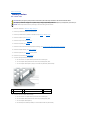
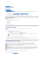
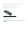
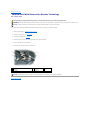
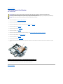
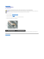
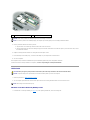
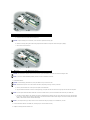
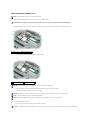
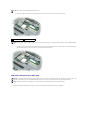
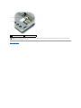
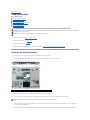
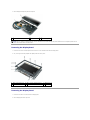
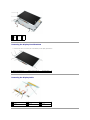
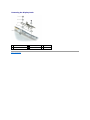
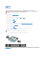
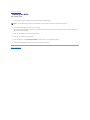
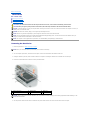
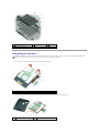
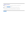
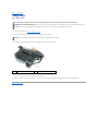
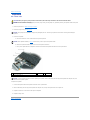
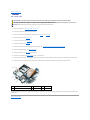
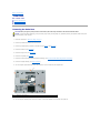
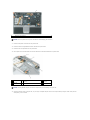
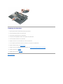
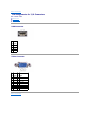
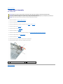
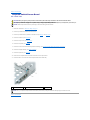
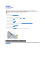
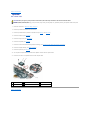
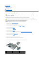
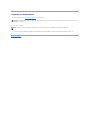
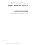
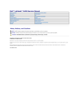
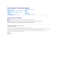
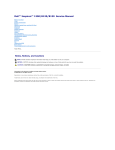
Dell™ Latitude™ D430 Service Manual
Before You Begin
Hard Drive
Hinge Cover
Keyboard
Coin-Cell Battery
Internal Card With Bluetooth® Wireless Technology
Memory and Mini-Cards
Display Assembly
Palm Rest
Speaker
Suspend-Switch Sensor Board
System Board
Fan
PC Card/Smart Card Reader
Modem
Wireless Switch
Power Button Assembly
Battery Latches
Pin Assignments for I/O Connectors
Flashing the BIOS
Notes, Notices, and Cautions
NOTE: A NOTE indicates important information that helps you make better use of your computer.
NOTICE: A NOTICE indicates either potential damage to hardware or loss of data and tells you how to avoid the problem.
CAUTION: A CAUTION indicates a potential for property damage, personal injury, or death.
Information in this document is subject to change without notice.
© 2007 Dell Inc. All rights reserved.
Reproduction in any manner whatsoever without the written permission of Dell Inc. is strictly forbidden.
Trademarks used in this text: Dell, the DELL logo, and InspironLatitude are trademarks of Dell Inc.; Bluetooth is a trademark owned by Bluetooth SIG, Inc. and is used by Dell Inc.
under license.
Other trademarks and trade names may be used in this document to refer to either the entities claiming the marks and names or their products. Dell Inc. disclaims any
proprietary interest in trademarks and trade names other than its own.
Model PP09S
June 2007 Rev. A00
Back to Contents Page
Battery Latches
Dell™ Latitude™ D430 CAUTION: Before you begin any of the procedures in this section, follow the safety instructions in the Product Information Guide.
CAUTION: To prevent static damage to components inside your computer, discharge static electricity from your body before you touch any of
your computer's electronic components. You can do so by touching an unpainted metal surface.
NOTICE: Handle components and cards by their edges, and avoid touching pins and contacts.
1.
Follow the instructions in "Before You Begin" on page 7.
2.
Remove any installed PC Cards from the PC Card slot.
3.
Remove any installed memory modules or Mini PCI cards (see Memory and Mini-Cards).
4.
Remove the hard drive (see Hard Drive).
5.
Remove the hinge cover (see Hinge Cover).
6.
Remove the keyboard (see Keyboard).
7.
Remove the internal card with Bluetooth® wireless technology (see Internal Card With Bluetooth® Wireless Technology).
8.
Remove the display assembly (see Display Assembly).
9.
Remove the palm rest (see Palm Rest) and lay it aside.
10.
Remove the system board (see System Board).
11.
To remove the longer battery-latch assembly:
a.
Use a screw driver or a plastic scribe to press down on the securing tab.
b.
Turn the computer base upside down and remove the protruding battery latch.
c.
Turn the computer base topside up and pry out and lift away the battery-latch assembly.
1
screw driver
2
longer battery-latch assembly
3
securing tab
4
computer base
12.
To remove the shorter battery-latch assembly:
a.
Use a screw driver or a plastic scribe to press down on the securing tab.
b.
Turn the computer base upside down and remove the protruding battery latch.
c.
Turn the computer base topside up.
d.
Pull the battery-latch assembly sideways out of the bracket and lift away the assembly.
1
screw driver
2
bracket
3
securing tab
4
shorter battery-latch assembly
5
computer base
Back to Contents Page
Back to Contents Page
Before You Begin
Dell™ Latitude™ D430 Recommended Tools
Turning Off Your Computer
Before Working Inside Your Computer
This chapter provides procedures for removing and installing the components in your computer. Unless otherwise noted, each procedure assumes that the
following conditions exist:
l
You have performed the steps in Turning Off Your Computer and Before Working Inside Your Computer.
l
You have read the safety information in the Dell™ Product Information Guide.
l
A component can be replaced or—if purchased separately—installed by performing the removal procedure in reverse order.
Recommended Tools
The procedures in this document may require the following tools:
l
Small flat-blade screwdriver
l
Phillips screwdriver
l
Small plastic scribe
l
Hex nut driver
l
Flash BIOS update program CD
Turning Off Your Computer
NOTICE: To avoid losing data, save and close all open files and exit all open programs before you turn off your computer.
1.
Shut down the operating system:
a.
Save and close all open files and exit all open programs.
b.
In the Microsoft® Windows® XP operating system, click Start® Shut Down® Shut down.
In Microsoft® Windows Vista™, click the Windows Vista Start button
corner of the Start menu as shown below, and then click Shut Down.
, in the lower-left corner of the desktop, click the arrow in the lower-right
The computer turns off after the operating system shutdown process is complete.
2.
Ensure that the computer and all attached devices are turned off. If your computer and attached devices did not automatically turn off when you shut
down your operating system, press and hold the power button for about 4 seconds to turn them off.
Before Working Inside Your Computer
Use the following safety guidelines to help protect your computer from potential damage and to help to ensure your own personal safety.
CAUTION: Before you begin any of the procedures in this section, follow the safety instructions in the Product Information Guide.
NOTICE: Handle components and cards with care. Do not touch the components or contacts on a card. Hold a card by its edges or by its metal
mounting bracket. Hold a component such as a processor by its edges, not by its pins.
NOTICE: Only a certified service technician should perform repairs on your computer. Damage due to servicing that is not authorized by Dell is not
covered by your warranty.
NOTICE: When you disconnect a cable, pull on its connector or on its pull-tab, not on the cable itself. Some cables have connectors with locking tabs; if
you are disconnecting this type of cable, press in on the locking tabs before you disconnect the cable. As you pull connectors apart, keep them evenly
aligned to avoid bending any connector pins. Also, before you connect a cable, ensure that both connectors are correctly oriented and aligned.
NOTICE: To avoid damaging the computer, perform the following steps before you begin working inside the computer.
1.
Ensure that the work surface is flat and clean to prevent the computer cover from being scratched.
2.
Turn off your computer (see Turning Off Your Computer).
3.
If the computer is connected to a docking device (docked), undock it. See the documentation that came with your docking device for instructions.
NOTICE: To disconnect a network cable, first unplug the cable from your computer and then unplug the cable from the network device.
4.
Disconnect all telephone or network cables from the computer.
5.
Close the display and turn the computer upside down on a flat work surface.
NOTICE: To avoid damaging the system board, you must remove the main battery before you service the computer.
6.
1
Disconnect your computer and all attached devices from their electrical outlets.
battery
7.
8.
battery-bay latch releases (2)
Remove the main battery:
a.
Slide the two battery-bay latch releases on the bottom of the computer.
b.
Remove the battery from the battery bay.
Press the power button to ground the system board.
Back to Contents Page
2
Back to Contents Page
Internal Card With Bluetooth® Wireless Technology
Dell™ Latitude™ D430 CAUTION: Before performing the following procedures, read the safety instructions in your Product Information Guide.
NOTICE: To avoid electrostatic discharge, ground yourself by using a wrist grounding strap or by periodically touching a connector on the back panel of
the computer.
NOTICE: To prevent damage to the system board, remove the main battery before you service the computer.
If you ordered an internal card with Bluetooth wireless technology with your computer, it is already installed.
1.
Follow the procedures in "Before You Begin" on page 7.
2.
Remove the hinge cover (see Hinge Cover).
3.
Remove the keyboard (see Keyboard).
4.
Remove the M2 x 3-mm screw from the card holder and lay the holder aside.
5.
Lift the card away from the aligning pin.
6.
Disconnect the card cable connector from the card.
1 internal card with Bluetooth wireless
technology
2 card cable
connector
3 M2 x 3-mm
screw
4 card holder
5 aligning pin
NOTICE: Be careful when removing the card to avoid damaging the card, card cable, or surrounding components.
Back to Contents Page
Back to Contents Page
PC Card/Smart Card Reader
Dell™ Latitude™ D430 CAUTION: Before you begin any of the procedures in this section, follow the safety instructions in the Product Information Guide.
CAUTION: To prevent static damage to components inside your computer, discharge static electricity from your body before you touch any of
your computer's electronic components. You can do so by touching an unpainted metal surface.
NOTICE: Handle components and cards by their edges, and avoid touching pins and contacts.
1.
Follow the instructions in "Before You Begin" on page 7.
2.
Remove any installed PC Cards from the PC Card slot.
3.
Remove any installed memory modules or Mini PCI cards (see Memory and Mini-Cards).
4.
Remove the hard drive (see Hard Drive).
5.
Remove the hinge cover (see Hinge Cover).
6.
Remove the keyboard (see Keyboard).
7.
Remove the internal card with Bluetooth® wireless technology (see Internal Card With Bluetooth® Wireless Technology).
8.
Remove the display assembly (see Display Assembly).
9.
Remove the palm rest (see Palm Rest).
10.
11.
1
Remove the system board (see System Board).
Turn the system board upside down and pull on the pull-tab to disconnect the PC Card/smart card reader connector from the bottom of the system
board.
pull-tab
12.
2
PC Card/smart card reader
PC Card/smart-card reader cable
Turn the system board topside up remove the reader from the system board.
Back to Contents Page
3
Back to Contents Page
Coin-Cell Battery
Dell™ Latitude™ D430 CAUTION: Before performing the following procedures, follow the safety instructions in your Product Information Guide.
NOTICE: To avoid electrostatic discharge, ground yourself by using a wrist grounding strap or by periodically touching a connector on the back panel of
the computer.
NOTICE: To prevent damage to the system board, remove the main battery before you service the computer.
1
1.
Follow the procedures in "Before You Begin" on page 7.
2.
Remove the keyboard (see Keyboard).
3.
Disconnect the coin-cell battery cable connector from the system board connector.
4.
Remove the coin-cell battery from the system board.
cable connector
2
coin-cell battery
When you replace the battery, insert it at a 30-degree angle under the clip with the positive (identified by a plus [+] symbol) side up, and then push it into
place.
Back to Contents Page
Back to Contents Page
Memory and Mini-Cards
Dell™ Latitude™ D430 Memory
Mini-Cards
Memory
You can increase your computer memory by installing memory modules on the system board. See "Specifications" in your computer User's Guide for information
about the memory supported by your computer. Install only memory modules that are intended for your computer.
NOTE: Memory modules purchased from Dell are covered under your computer warranty.
CAUTION: Before you begin any of the procedures in this section, follow the safety instructions in the Product Information Guide.
NOTICE: To prevent damage to the system board, remove the main battery before you service the computer.
This computer has one memory module connector labeled "DIMM A." To install a memory module in DIMM A:
1.
Follow the procedures in "Before You Begin" on page 7.
2.
Turn the computer upside down, loosen the three captive screws on the memory/Mini-Card module cover, and remove the cover.
3.
Ground yourself by touching one of the metal connectors on the back of the computer.
NOTICE: If you leave your work area, ground yourself again when you return to the computer.
4.
If you are replacing a memory module, remove the existing module:
NOTICE: To prevent damage to the memory module connector, do not use tools to spread the memory-module securing clips.
a.
Use your fingertips to carefully spread apart the securing clips on each end of the memory module connector until the module pops up.
b.
Remove the module from the connector.
1
memory module
2
securing clips (2)
NOTICE: Insert memory modules at a 45-degree angle to prevent damage to connectors.
NOTE: If the memory module is not installed properly, the computer may not boot properly. No error message indicates this failure.
5.
Ground yourself and install the new memory module:
a.
Align the notch in the module edge connector with the tab in the connector slot.
b.
Slide the module firmly into the slot at a 45-degree angle, and rotate the module down until it clicks into place. If you do not feel the click, remove
the module and reinstall it.
6.
Replace the memory/Mini-Card module cover and tighten the three captive screws.
7.
Insert the battery into the battery bay, or connect the AC adapter to your computer and an electrical outlet.
8.
Turn on the computer.
As the computer boots, it detects the additional memory and automatically updates the system configuration information.
To confirm the amount of memory installed in the computer, click Start® Help and Support® Dell System Information.
Mini-Cards
CAUTION: Before you begin any of the procedures in this section, follow the safety instructions in the Product Information Guide.
NOTICE: To prevent damage to the system board, remove the main battery before you service the computer.
1.
Follow the procedures in "Before You Begin" on page 7.
2.
Turn the computer upside down and loosen the three captive screws on the memory/Mini-Card module cover and remove the cover.
NOTE: Cable routing for the Mini-Cards may vary.
Wireless Local Area Network (WLAN) Cards
1.
If a WLAN card is not already installed, go to step 2. If you are replacing a WLAN card, remove the existing card:
1
antenna cables (2)
a.
Disconnect the antenna cables from the WLAN card.
NOTICE: To prevent damage to the connector, do not use tools to spread the securing clips.
1
b.
Release the card by pushing the metal securing clips toward the back of the computer until the card pops up slightly.
c.
Lift the card out of its connector.
WLAN card
2
metal securing clips (2)
NOTICE: The connectors are keyed to ensure correct insertion. If you feel resistance, check the connectors and realign the card.
NOTE: Do not insert a Mobile Broadband (WWAN) network card into the WLAN card connector.
2.
Install the WLAN card:
NOTICE: To avoid damaging the WLAN card, never place cables on top of or under the card.
NOTE: The WLAN card may have two or three antenna connectors, depending on the type of card you ordered.
a.
Move any antenna cables out of the way to make space for the WLAN card.
b.
Align the WLAN card with the connector at a 45-degree angle, and press the card down into the securing clips until the card clicks into place.
NOTE: For more specific information about which cable to connect to which connector, see the documentation that came with your WLAN card.
c.
Connect the antenna cables to the antenna connectors on the WLAN card by matching the color of the cable to the color of the triangle above
the connector. Connect the main antenna cable (white) to the antenna connector with the white triangle. Connect the auxiliary antenna cable
(black) to the antenna connector with the black triangle.
NOTE: If your computer has a gray cable, connect it to the connector with the gray triangle, if one is available on your card.
3.
Connect the antenna cables to the WLAN card, ensuring that you route the cables correctly.
4.
Replace the memory/Mini-Card module cover.
Mobile Broadband (WWAN) Cards
NOTE: Mobile Broadband cards may not be available in all regions.
If you ordered a Mobile Broadband card with your computer, the card is already installed.
CAUTION: Before you begin any of the procedures in this section, follow the safety instructions in the Product Information Guide.
1.
If a Mobile Broadband card is not already installed, go to step 5. If you are replacing a Mobile Broadband card, remove the existing card:
1 antenna wires (2) 2 Mobile Broadband card
a.
Disconnect the Mobile Broadband card from any attached cables.
1 Mobile Broadband card 2 metal securing tabs (2)
NOTICE: To prevent damage to the connector, do not use tools to spread the securing clips.
b.
Use your fingertips to carefully spread apart the metal securing tabs until the card pops up slightly.
c.
Slide and lift the Mobile Broadband card out of its connector.
NOTICE: The connectors are keyed to ensure correct insertion. If you feel resistance, check the connectors and realign the card.
NOTE: Do not insert a WLAN card into the Mobile Broadband card slot.
NOTICE: The Mobile Broadband card may have one or two connectors, depending on the type of card you ordered.
2.
To install a Mobile Broadband card:
a.
Move any antenna cables out of the way to make space for the card.
NOTICE: To avoid damaging the Mobile Broadband card, never place cables on top of or under the card and ensure that you route the cables properly.
NOTE: Cable routing for the Mobile Broadband card may vary.
b.
Align the card with the connector at a 45-degree angle, and press the card into the connector until you feel a click.
1 Mobile Broadband card 2 system board connector
NOTE: For more specific information about which cable to connect to which connector, see the documentation that came with your Mobile Broadband
card.
c.
Connect the white antenna cable with the black stripe to the connector on the card marked with a white triangle; connect the black antenna
cable with the white stripe to the connector on the card marked with a black triangle.
Subscriber Identity Module (SIM) Card
NOTICE: To protect the SIM card from electrostatic discharge (ESD), do not touch the SIM card connector. Also, take care when removing the card to
slide the card completely out of the metal tabs before lifting the card out of the slot. The card is brittle and may easily break otherwise.
NOTE: The SIM card is located in the battery bay. You must remove the main battery before you can access the SIM card.
1.
Slide the SIM card out of the SIM card slot with the cut-off corner of the card facing toward the back of the computer.
1 metal tabs (2) on SIM card slot 2 SIM card with cut-off corner
NOTE: When you replace the SIM card, ensure that you slide the SIM card under the two metal tabs on the SIM card slot with the cut-off corner of the
card facing toward the back of the computer.
Back to Contents Page
Back to Contents Page
Display Assembly
Dell™ Latitude™ D430 Removing the Display Assembly
Removing the Display Bezel
Removing the Display Panel
Removing the Display-Panel Brackets
Removing the Display Cable
Removing the Display Latch
CAUTION: Before you begin any of the procedures in this section, follow the safety instructions in the Product Information Guide.
NOTICE: To avoid electrostatic discharge, ground yourself by using a wrist grounding strap or by periodically touching an unpainted metal surface (such
as the back panel) on the computer.
NOTICE: You must remove the display assembly before you remove the palm rest.
1.
Follow the instructions in "Before You Begin" on page 7.
2.
Remove the hinge cover (see Hinge Cover).
3.
Remove the keyboard (see Keyboard).
4.
Remove the internal card with Bluetooth® wireless technology (see Internal Card With Bluetooth® Wireless Technology).
Removing the Display Assembly
1.
Remove the two M2.5 x 5-mm left and right hinge screws from the back of the computer.
2.
Turn the computer upside down and remove the two M2.5 x 5-mm screws labeled "D" from the computer base.
1
M2.5 x 5-mm screws (4)
3.
Remove the antenna cables from the WLAN and Mobile Broadband Mini- Cards, if applicable.
4.
Turn the computer over topside up and open the display approximately 180 degrees so that it lies flat against your work surface.
NOTE: Ensure that any plastic sleeves that protect unconnected Mini-Card connectors do not slide off.
5.
6.
Carefully dislodge the Mini-Card antenna cables from their routing guides and pull the cables with their connectors through the system board so that
they are clear of the computer base.
Pull on the display cable pull-tab toward the back of the computer to disconnect the display cable from the display connector on the system board.
7.
1
Lift the display assembly away from the computer.
Mini-Card antenna cables
2
display cable
3
display assembly
NOTE: When you replace the display assembly, route the Mini-Card antenna cables through the system board and turn the computer upside down to
connect the antenna cables to the Mini-Cards.
Removing the Display Bezel
1.
Remove the six screw covers/bumpers and the six M2.5 x 4.2-mm shoulder screws from the display bezel.
2.
Use your fingers to carefully separate the display bezel from the top cover.
1
screw covers/bumpers (6)
2
M2.5 x 4.2-mm shoulder screws (6)
3 display bezel
4
top cover
Removing the Display Panel
1.
Remove the two M2 x 3-mm screws from the display panel.
2.
Lift the display panel off the top cover.
1 M2 x
2 display 3 top
3-mm
panel
cover
screws
(2)
Removing the Display-Panel Brackets
1.
1
Remove the four M2 x 3-mm screws (two on each bracket) from the display-panel brackets.
display-panel brackets (2)
2
M2 x 3-mm screws (4)
3
display panel
Removing the Display Cable
1 back of display-panel cable
assembly
2 pull-tab on inverter
connector
3 bottom flex-cable
connector
4 top flex-cable connector
Removing the Display Latch
1
M2 x 3-mm screws (2)
2
screw holders (2)
3
display latch
4
metal plate
5
display base
Back to Contents Page
Back to Contents Page
Fan
Dell™ Latitude™ D430 CAUTION: Before you begin any of the procedures in this section, follow the safety instructions in the Product Information Guide.
CAUTION: To prevent static damage to components inside your computer, discharge static electricity from your body before you touch any of
your computer's electronic components. You can do so by touching an unpainted metal surface.
NOTICE: Handle components and cards by their edges, and avoid touching pins and contacts.
1.
Follow the instructions in "Before You Begin" on page 7.
2.
Remove any installed PC Cards from the PC Card slot.
3.
Remove any installed memory modules or Mini PCI cards (see Memory and Mini-Cards).
4.
Remove the hard drive (see Hard Drive).
5.
Remove the hinge cover (see Hinge Cover).
6.
Remove the keyboard (see Keyboard).
7.
Remove the internal card with Bluetooth® wireless technology (see Internal Card With Bluetooth® Wireless Technology).
8.
Remove the display assembly (see Display Assembly).
9.
Remove the palm rest (see Palm Rest) and lay it aside.
10.
Remove the system board (see System Board) and remove the fan connector from the top of the system board.
11.
Turn the system board upside down.
NOTICE: Ensure that you have moved any cables out of the way before you lift away the fan.
12.
Loosen the three captive screws from the fan, and lift the fan away from bottom of the system board.
1 modem cable
2 captive screws (3)
3 bottom of system board
4 fan assembly
5 fan connector on top of the system board
Back to Contents Page
Back to Contents Page
Flashing the BIOS
Dell™ Latitude™ D430 1.
Ensure that the AC adapter is plugged in and that the main battery is installed properly.
NOTE: If you use a BIOS update program CD to flash the BIOS, set up the computer to boot from a CD before inserting the CD.
2.
Insert the BIOS update program CD, and turn on the computer.
Follow the instructions that appear on the screen. The computer continues to boot and updates the new BIOS. When the flash update is complete, the
computer will automatically reboot.
3.
Press <F2> during POST to enter the system setup program.
4.
Press <Alt><F> to reset the computer defaults.
5.
Press <Esc Suspend>, select Save changes and reboot, and press <Enter> to save configuration changes.
6.
Remove the flash BIOS update program CD from the drive and restart the computer.
Back to Contents Page
Back to Contents Page
Hard Drive
Dell™ Latitude™ D430 Removing the Hard Drive
Dismantling the Hard Drive
Replacing the Hard Drive
CAUTION: If you remove the hard drive from the computer when the drive is hot, do not touch the metal housing of the hard drive.
CAUTION: Before you begin any of the procedures in this section, follow the safety instructions in the Product Information Guide.
NOTICE: To prevent data loss, turn off your computer before removing the hard drive. Do not remove the hard drive while the computer is turned on, in
standby mode, or in hibernate mode.
NOTICE: Hard drives are extremely fragile; even a slight bump can damage the drive.
NOTE: Dell does not guarantee compatibility or provide support for hard drives from sources other than Dell. NOTE: You need the Operating System CD to install the Microsoft® Windows® operating system. You also need the Drivers and Utilities CD for your
computer to install the drivers and utilities on the new hard drive.
NOTE: This computer is not equipped with an optical drive—use the Media Base (sold separately) to install software.
Removing the Hard Drive
1.
Follow the procedures in "Before You Begin" on page 7.
NOTE: Before you remove the hard drive, ensure that you removed the main battery.
2.
Turn the computer upside down, and loosen the two captive screws on the metal bracket that holds the hard drive.
3.
Holding the bracket by the sides, slide it toward the back of the computer to dislodge the bracket from underneath the two metal clips.
4.
Remove the metal bracket from the hard drive and lay the bracket aside.
1
captive screws (2)
2
metal bracket
3
hard drive
4
metal clips (2)
NOTICE: When the hard drive is not in the computer, store it in protective antistatic packaging. See "Protecting Against Electrostatic Discharge" in the
Product Information Guide.
5.
Use the pull-tab to disconnect the hard drive cable from the system board connector and remove the hard drive from the computer.
1
pull-tab
2
hard drive cable
3
hard drive
4
system board connector
Dismantling the Hard Drive
NOTICE: The replacement hard drive ships with the protective cover and the hard drive cable. Only a certified service technician should dismantle the
hard drive. Damage due to servicing that is not authorized by Dell is not covered by your warranty.
1.
1
protective cover
2.
1
Use your fingers to carefully remove the protective cover from the hard drive.
2
hard drive
Use a hard drive tool to carefully pry up the ZIF connector that holds the hard drive cable, and remove the cable.
ZIF connector
2
hard drive cable
Replacing the Hard Drive
NOTICE: Use firm and even pressure to slide the drive into place. If you use excessive force, you may damage the connector.
1.
Follow the steps in Removing the Hard Drive in reverse order.
NOTE: This computer is not equipped with an optical drive—use the Media Base (sold separately) to install software.
2.
Install the operating system for your computer (see "Restoring Your Operating System" in your computer User's Guide).
3.
Install the drivers and utilities for your computer (see "Reinstalling Drivers and Utilities" in your computer User's Guide).
Back to Contents Page
Back to Contents Page
Hinge Cover
Dell™ Latitude™ D430 CAUTION: Before you begin any of the procedures in this section, follow the safety instructions in the Product Information Guide.
NOTICE: To avoid electrostatic discharge, ground yourself by using a wrist grounding strap or by periodically touching an unpainted metal surface (such
as a connector on the back of the computer).
NOTICE: The hinge cover is fragile and can be damaged if extreme force is used. Be careful when removing the hinge cover.
1.
Follow the procedures in "Before You Begin" on page 7.
2.
Open the display all the way (180 degrees) so that it rests on your work surface.
NOTICE: To avoid damaging the hinge cover, do not lift the cover on both sides simultaneously.
3.
1
Starting on the right side of the computer, use a plastic scribe to pry up the hinge cover.
hinge cover
4.
2
plastic scribe
Ease the hinge cover up, moving from right to left, and remove it.
To replace the hinge cover, insert the left edge of the cover into the hinge cover slot, and press from left to right until the cover snaps into place.
Back to Contents Page
Back to Contents Page
Keyboard
Dell™ Latitude™ D430 CAUTION: Before you begin any of the procedures in this section, follow the safety instructions in the Product Information Guide.
NOTICE: To avoid electrostatic discharge, ground yourself by using a wrist grounding strap or by periodically touching an unpainted metal surface (such
as a connector on the back of the computer).
1.
Follow the procedures in "Before You Begin" on page 7.
2.
Remove the hinge cover (see Hinge Cover).
NOTICE: The keycaps on the keyboard are fragile, easily dislodged, and time- consuming to replace. Be careful when removing and handling the
keyboard.
3.
Remove the keyboard:
a.
Remove the three M2 x 3-mm screws across the top of the keyboard.
NOTICE: Lift the keyboard carefully in step b to ensure that you do not pull on the keyboard cable.
b.
Rotate the keyboard forward to gain access to the two keyboard connectors.
c.
Pull up on the plastic bars on the keyboard connectors to disconnect the keyboard connectors from the system board.
1
plastic bars on keyboard connectors
2
tabs (4)
3
keyboard
4
M2 x 3-mm screws (3)
NOTICE: To avoid scratching the palm rest when replacing the keyboard, hook the tabs along the front edge of the keyboard into the palm rest, and
then secure the keyboard in place.
To replace the keyboard:
1.
Connect the keyboard cable to the keyboard connectors on the system board.
2.
Place the tabs along the front edge of the keyboard into the palm rest, and lay the keyboard down on the palm rest.
3.
Replace the three M2 x 3-mm screws at the top of the keyboard.
4.
Replace the hinge cover.
Back to Contents Page
Back to Contents Page
Modem
Dell™ Latitude™ D430 CAUTION: Before you begin any of the procedures in this section, follow the safety instructions in the Product Information Guide.
CAUTION: To prevent static damage to components inside your computer, discharge static electricity from your body before you touch any of
your computer's electronic components. You can do so by touching an unpainted metal surface.
NOTICE: Handle components and cards by their edges, and avoid touching pins and contacts.
1.
Follow the instructions in "Before You Begin" on page 7.
2.
Remove any installed PC Cards from the PC Card slot.
3.
Remove any installed memory modules or Mini PCI cards (see Memory and Mini-Cards).
4.
Remove the hard drive (see Hard Drive).
5.
Remove the hinge cover (see Hinge Cover).
6.
Remove the keyboard (see Keyboard).
7.
Remove the internal card with Bluetooth® wireless technology (see Internal Card With Bluetooth® Wireless Technology).
8.
Remove the display assembly (see Display Assembly).
9.
Remove the palm rest (see Palm Rest) and lay it aside.
10.
Remove the system board (see System Board) and turn it upside down.
11.
Remove the modem connector from the bottom of the system board and carefully dislodge the modem cable from the metal clips on the system board.
12.
Remove the M2 x 3-mm modem screw and pull up on the modem pull-tab to remove the modem from its socket on the system board.
1
M2 x 3-mm screw
2
pull-tab
3
modem
4
modem connector
To replace the modem, ensure that the modem is properly aligned with the socket and that you route the modem cable correctly under the metal clips on the
system board.
Back to Contents Page
Back to Contents Page
Palm Rest
Dell™ Latitude™ D430 Removing the Palm Rest
Replacing the Palm Rest
Removing the Palm Rest
CAUTION: Before you begin any of the procedures in this section, follow the safety instructions in the Product Information Guide.
NOTICE: To avoid electrostatic discharge, ground yourself by using a wrist grounding strap or by periodically touching an unpainted metal surface (such
as the back panel) on the computer.
1.
Follow the instructions in "Before You Begin" on page 7.
2.
Remove any installed PC Cards from the PC Card slot.
3.
Remove any installed memory modules or Mini PCI cards (see Memory and Mini-Cards).
4.
Remove the hard drive (see Hard Drive).
5.
Remove the hinge cover (see Hinge Cover).
6.
Remove the keyboard (see Keyboard).
7.
Remove the internal card with Bluetooth® wireless technology (see Internal Card With Bluetooth® Wireless Technology).
8.
Remove the display assembly (see Display Assembly).
9.
Turn the computer upside down and remove the seven M2.5 x 5-mm screws from the computer base.
1
10.
M2.5 x 5-mm screws (7)
Turn the computer topside up and remove the six M2.5 x 5-mm screws labeled "P" from the top of the palm rest.
1
M2.5 x 5-mm screws (6)
NOTICE: Pull on the plastic tab on top of the connectors to avoid damaging the connectors.
11.
Disconnect the speaker connector from the system board.
12.
Disconnect the Secure Digital/SIM card reader cable from the system board.
13.
Disconnect the touch pad cable from the system board.
14.
Lift the plastic bar on the LED board connector and disconnect the LED board cable from the system board.
1 speaker connector
2 Secure Digital/SIM card reader cable
connector
3 LED board
connector
4 touch pad
connector
NOTICE: Carefully separate the palm rest from the computer base to avoid damage to the palm rest.
15.
Starting at the back center of the palm rest, use your fingers to separate the palm rest from the computer base by lifting the inside of the palm rest
while pushing in on the outside.
Replacing the Palm Rest
1.
Align the palm rest with the computer base and gently snap into place.
2.
Connect the LED board connector to the system board.
3.
Connect the touch pad connector to the system board.
4.
Connect the Secure Digital/SIM card reader cable connector to the system board.
5.
Connect the speaker connector to the system board.
6.
Replace the six M2.5 x 5-mm screws labeled "P" on the top of the palm rest.
7.
Turn the computer upside down and replace the seven M2.5 x 5-mm screws in the computer base.
8.
Replace the display assembly (see Display Assembly).
9.
Replace the internal card with Bluetooth® wireless technology (see Internal Card With Bluetooth® Wireless Technology).
10.
Replace the keyboard (see Keyboard).
11.
Replace the hinge cover (see Hinge Cover).
Back to Contents Page
Back to Contents Page
Pin Assignments for I/O Connectors
Dell™ Latitude™ D430 USB Connector
Video Connector
USB Connector
Pin Signal
1
USB5V+
2
USBP–
3
USBP+
4
GND
Video Connector
Pin Signal Pin Signal
1
CRT_R 9
5V+
2
CRT_G 10
GND
3
CRT_B 11
MONITOR_DETECT–
4
NC
12
DDC_DATA
5
GND
13
CRT_HS
6
GND
14
CRT_VS
7
GND
15
DDC_CLK
8
GND
Back to Contents Page
Back to Contents Page
Power Button Assembly
Dell™ Latitude™ D430 CAUTION: Before you begin any of the procedures in this section, follow the safety instructions in the Product Information Guide.
CAUTION: To prevent static damage to components inside your computer, discharge static electricity from your body before you touch any of
your computer's electronic components. You can do so by touching an unpainted metal surface.
NOTICE: Handle components and cards by their edges, and avoid touching pins and contacts.
1.
Follow the instructions in "Before You Begin" on page 7.
2.
Remove any installed PC Cards from the PC Card slot.
3.
Remove any installed memory modules or Mini PCI cards (see Memory and Mini-Cards).
4.
Remove the hard drive (see Hard Drive).
5.
Remove the hinge cover (see Hinge Cover).
6.
Remove the keyboard (see Keyboard).
7.
Remove the internal card with Bluetooth® wireless technology (see Internal Card With Bluetooth® Wireless Technology).
8.
Remove the display assembly (see Display Assembly).
9.
Remove the palm rest (see Palm Rest).
10.
Disconnect the power-button assembly connector from the system board.
11.
Push the assembly toward the inside of the computer base and lift out.
1
power button assembly
Back to Contents Page
2
computer base
Back to Contents Page
Suspend-Switch Sensor Board
Dell™ Latitude™ D430 CAUTION: Before you begin any of the procedures in this section, follow the safety instructions in the Product Information Guide.
CAUTION: To prevent static damage to components inside your computer, discharge static electricity from your body before you touch any of
your computer's electronic components. You can do so by touching an unpainted metal surface.
NOTICE: Handle components and cards by their edges, and avoid touching pins and contacts.
1.
Follow the instructions in "Before You Begin" on page 7.
2.
Remove any installed PC Cards from the PC Card slot.
3.
Remove any installed memory modules or Mini PCI cards (see Memory and Mini-Cards).
4.
Remove the hard drive (see Hard Drive).
5.
Remove the hinge cover (see Hinge Cover).
6.
Remove the keyboard (see Keyboard).
7.
Remove the internal card with Bluetooth® wireless technology (see Internal Card With Bluetooth® Wireless Technology).
8.
Remove the display assembly (see Display Assembly).
9.
Remove the palm rest (see Palm Rest).
10.
Disconnect the suspend-switch sensor board connector from the system board.
11.
Remove the M2 x 3-mm screw and lift the suspend-switch sensor board away.
1
M2 x 3-mm screw
2
suspense-switch sensor board
3
aligning pin
NOTE: When you replace the suspend-switch sensor board, ensure that you align the board with the aligning pin and the screw hole.
Back to Contents Page
Back to Contents Page
Wireless Switch
Dell™ Latitude™ D430 CAUTION: Before you begin any of the procedures in this section, follow the safety instructions in the Product Information Guide.
CAUTION: To prevent static damage to components inside your computer, discharge static electricity from your body before you touch any of
your computer's electronic components. You can do so by touching an unpainted metal surface.
NOTICE: Handle components and cards by their edges, and avoid touching pins and contacts.
1.
Follow the instructions in "Before You Begin" on page 7.
2.
Remove any installed PC Cards from the PC Card slot.
3.
Remove any installed memory modules or Mini PCI cards (see Memory and Mini-Cards).
4.
Remove the hard drive (see Hard Drive).
5.
Remove the hinge cover (see Hinge Cover).
6.
Remove the keyboard (see Keyboard).
7.
Remove the internal card with Bluetooth® wireless technology (see Internal Card With Bluetooth® Wireless Technology).
8.
Remove the display assembly (see Display Assembly).
9.
Remove the palm rest (see Palm Rest) and lay it aside.
10.
Remove the system board (see System Board).
11.
Use a screw driver or plastic scribe to carefully pry the wireless switch from the wall of the computer base.
1
computer base
Back to Contents Page
2
wireless switch
3
screw driver
Back to Contents Page
Speaker
Dell™ Latitude™ D430 CAUTION: Before you begin any of the procedures in this section, follow the safety instructions in the Product Information Guide.
NOTICE: To avoid electrostatic discharge, ground yourself by using a wrist grounding strap or by periodically touching an unpainted metal surface (such
as the back panel) on the computer.
1.
Follow the instructions in "Before You Begin" on page 7.
2.
Remove any installed PC Cards from the PC Card slot.
3.
Remove any installed memory modules or Mini PCI cards (see Memory and Mini-Cards).
4.
Remove the hard drive (see Hard Drive).
5.
Remove the hinge cover (see Hinge Cover).
6.
Remove the keyboard (see Keyboard).
7.
Remove the internal card with Bluetooth® wireless technology (see Internal Card With Bluetooth® Wireless Technology).
8.
Remove the display assembly (see Display Assembly).
9.
Remove the palm rest (see Palm Rest).
10.
Turn the palm rest upside down and disconnect the speaker connector from the system board.
11.
Remove the two M2 x 3-mm speaker screws from the computer base.
1
speaker
2 M2 x 3-mm speaker screws (2)
3
speaker cables routing
4
bottom of palm rest
Back to Contents Page
Back to Contents Page
System Board
Dell™ Latitude™ D430 Removing the System Board
Replacing the System Board
Removing the System Board
CAUTION: Before you begin any of the procedures in this section, follow the safety instructions in the Product Information Guide.
NOTICE: To avoid electrostatic discharge, ground yourself by using a wrist grounding strap or by periodically touching an unpainted metal surface (such
as the back panel) on the computer.
The system board's BIOS chip contains the Service Tag, which is also visible on a barcode label on the bottom of the computer. The replacement kit for the
system board includes a CD that provides a utility for transferring the Service Tag to the replacement system board.
CAUTION: Before you begin any of the procedures in this section, follow the safety instructions in the Product Information Guide.
CAUTION: To prevent static damage to components inside your computer, discharge static electricity from your body before you touch any of
your computer's electronic components. You can do so by touching an unpainted metal surface.
NOTICE: Handle components and cards by their edges, and avoid touching pins and contacts.
1.
Follow the instructions in "Before You Begin" on page 7.
2.
Remove any installed PC Cards from the PC Card slot.
3.
Remove any installed memory modules or Mini PCI cards (see Memory and Mini-Cards).
4.
Remove the hard drive (see Hard Drive).
5.
Remove the hinge cover (see Hinge Cover).
6.
Remove the keyboard (see Keyboard).
7.
Remove the internal card with Bluetooth® wireless technology (see Internal Card With Bluetooth® Wireless Technology).
8.
Remove the display assembly (see Display Assembly).
9.
Remove the palm rest (see Palm Rest).
10.
Disconnect the power button connector from the system board.
11.
Disconnect the suspend-switch sensor board connector from the system board.
12.
Remove the remaining two M2.5 x 5-mm screws that secure the system board to the computer base.
13.
Lift the system board at an angle toward the side of the computer and out of the computer base.
1 computer base
2 M2.5 x 5-mm screws (2)
3 system board assembly
4 power button connector
5 suspend-switch sensor board
Replacing the System Board
1.
Follow all of the steps in Removing the System Board in reverse order.
NOTICE: Before turning on the computer, replace all screws and ensure that no stray screws remain inside the computer. Failure to do so may result in
damage to the computer.
2.
Turn on the computer.
NOTE: After you have replaced the system board, enter the computer Service Tag into the BIOS of the replacement system board.
3.
Insert the CD that accompanied the replacement system board into the appropriate drive. Follow the instructions that appear on the screen.
Back to Contents Page
Back to Contents Page
Dell™ Latitude™ D430 Notes, Notices, and Cautions
NOTE: A NOTE indicates important information that helps you make better use of your computer.
NOTICE: A NOTICE indicates either potential damage to hardware or loss of data and tells you how to avoid the problem.
CAUTION: A CAUTION indicates a potential for property damage, personal injury, or death.
Information in this document is subject to change without notice.
© 2007 Dell Inc. All rights reserved.
Reproduction in any manner whatsoever without the written permission of Dell Inc. is strictly forbidden.
Trademarks used in this text: Dell, the DELL logo, and InspironLatitude are trademarks of Dell Inc.; Bluetooth is a trademark owned by Bluetooth SIG, Inc. and is used by Dell Inc.
under license.
Other trademarks and trade names may be used in this document to refer to either the entities claiming the marks and names or their products. Dell Inc. disclaims any
proprietary interest in trademarks and trade names other than its own.
June 2007 Rev. A00
Back to Contents Page