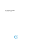
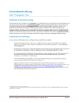
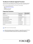
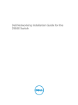
1
Basic Layer 2 Setup and Buffer Tuning of the
S25P for Storage Environments
Introduction
This document is intended for the users of S-Series S25P switches running FTOS 7.8.1.0 and configured
for use in a storage environment. This document describes:
•
•
•
•
Using the console port to enable all ports on the switch for Layer 2 switching
Verifying that the installed FTOS software is FTOS 7.8.1.0
Setting up passwords for managing the switch. For details on management, see the Management
chapter in the FTOS Configuration Guide for the S-Series and the Control and Monitoring chapter in
the FTOS Command Reference for the S-Series.
Optimizing the buffer for use in pure storage environments
This document does not cover:
•
•
•
Installing optional modules. For installation details, see the document Installing S25P Systems. For a
configuration example, see Figure 7 on page 6 here.
Adding the switch to an S-Series stack. For stacking configuration details, see the Stacking chapters in
the Configuration Guide and the Command Reference listed above.
Layer 3 (IP addressing) configuration. For details, see the Interfaces and IP Addressing chapters in the
Configuration Guide and Interface Commands chapter in the Command Reference listed above.
The full S-Series documentation set is available on the Technical Documentation CD-ROM and from the
Documentation tab of iSupport at the Force10 Networks website:
https://www.force10networks.com/CSPortal20/KnowledgeBase/Documentation.aspx
This document contains the following sections:
•
•
•
•
Accessing the Console Port on page 2
Setting Up Passwords on page 3
Setting Up Layer 2 Switching on page 4
Managing the Buffer Profile and Setting up Flow Control on page 5
101-00337-00
1
Accessing the Console Port
Step
Task
1
Install a straight-through RJ-45 copper cable (a standard Ethernet cable) between your system and the console
port of the S-Series switch. The console port is at the far left of the faceplate.
2
Turn on the switch by connecting it to power (there is no on/off button).
3
After the switch boots up (the status messages stop), press Enter twice to get the EXEC mode prompt. You
should see Force10>, as shown below.
Verifying the Software Release and S-Series Model
Unless you know that your system has already been installed with FTOS 7.8.1.0 or later, verify that the
required version is installed.
Task
Command Syntax
Command Mode
Display the installed FTOS version and S-Series model.
show inventory
EXEC
After typing show inventory, press Enter. The system replies with the type of output shown below. In this
case, “System Name” (S-Series model type) is “S25P” and “Software version” is “7.8.1.0”.
The following screenshot illustrates the expected output of the show inventory command:
Force10>show inventory
System Name
: S25P
System Mode
: 1.0
Software Version
: 7.8.1.0
Unit Type
Serial Number Part Number Revision
-------------------------------------------------------------* 0 S25-01-GE-24P
DL277000000
7590004800
B
0 S50-PWR-AC
N/A
N/A
N/A
0 S50-FAN
N/A
N/A
N/A
* - Management Unit
Software Protocol Configured
-------------------------------------------------------------Force10>
If your system does not have the correct software version installed, see the S-Series and FTOS Release
Notes, Version 7.8.1.0 for upgrade instructions. A printed copy should be included with your system.
Alternatively, see the printed Readme First document that is included with your system.
2
Basic Layer 2 Setup and Buffer Tuning of the S25P for Storage Environments
Setting Up Passwords
Step
Task
Command Syntax
Command Mode
1
Go from EXEC mode to EXEC privilege mode, commonly
called enable mode. After you enter enable and press Enter,
the prompt changes to: Force10#
enable
EXEC
2
Go from EXEC privilege mode to CONFIGURATION mode.
The prompt changes to: Force10(conf)#
config
EXEC privilege
3
Create a password for remote access (through Telnet).
For example, for the username “admin” with password
“admin”, enter username admin password admin.
username name
password password
CONFIGURATION
4
Create a password for access to Command Line Interface
(CLI) modes beyond the EXEC mode. This is typically called
the enable password.
For example, to create the enable password “admin”, enter
enable password admin.
enable password
password
CONFIGURATION
The following screenshot illustrates the use of these commands:
Force10>enable
Force10#config
Force10(config)#username admin password admin
Force10(config)#enable password admin
Force10(config)#
You can see the result of setting up a password, or of the other configuration changes that you make by
entering, in EXEC privilege mode, show running-config. The following screenshot shows the running
configuration from its top up to the part that displays the result of using the commands, above:
Force10#show run
Current Configuration ...
! Version 7.8.1.0
! Last configuration change at Wed Oct 27 17:55:30 2008 by default
!
redundancy disable-auto-reboot stack-unit
!
hardware watchdog
!
hostname Force10
!
enable password 7 b125455cf679b208e79b910e85789edf
!
username admin password 0 admin
In this case, the password was selected to be encrypted, so the result displayed is encrypted. For details on
setting passwords, see the Getting Started chapter in the FTOS Configuration Guide for the S-Series and
the Security chapter in the FTOS Command Reference for the S-Series.
For details on using the show running-config command, see the File Management chapter in the FTOS
Command Reference for the S-Series.
101-00337-00
3
Setting Up Layer 2 Switching
Step
Task
Command Syntax
Command Mode
Select all ports.
This example assumes that the stack ID is 0.
The prompt changes to:
Force10(conf-if-range-gi-0/1-24)#
interface range gi 0/1 - 24
CONFIGURATION
2
Enable the selected ports for Layer 2 switching.
switchport
INTERFACE RANGE
3
Set the maximum Link MTU (frame size) to handle
Jumbo frames.
mtu 9252
INTERFACE RANGE
4
Administratively enable all ports.
no shutdown
INTERFACE RANGE
5
Return to CONFIGURATION mode.
exit
INTERFACE RANGE
6
Repeat the above sequence for the 10GbE ports.
interface range te 0/25 - 28
CONFIGURATION
7
After physically connecting the ports, use the show
ip interfaces brief command to inspect
administrative status (the Status field in the output)
and link status (the Protocol field).
do show ip interfaces brief
INTERFACE RANGE
1
(A space is required before and
after the dash in the command.)
The following screenshot illustrates the use of these commands (use a space before and after the hyphen):
Force10(config)#interface range gigabitethernet 0/1 - 24
Force10(conf-if-range-gi-0/1-48)#switchport
Force10(conf-if-range-gi-0/1-48)#mtu 9252
Force10(conf-if-range-gi-0/1-48)#no shutdown
21:22:23: %STKUNIT0-M:CP %IFMGR-5-ASTATE_UP: Changed interface
21:22:23: %STKUNIT0-M:CP %IFMGR-5-ASTATE_UP: Changed interface
21:22:23: %STKUNIT0-M:CP %IFMGR-5-ASTATE_UP: Changed interface
21:22:23: %STKUNIT0-M:CP %IFMGR-5-ASTATE_UP: Changed interface
21:22:23: %STKUNIT0-M:CP %IFMGR-5-ASTATE_UP: Changed interface
21:22:23: %STKUNIT0-M:CP %IFMGR-5-ASTATE_UP: Changed interface
21:22:23: %STKUNIT0-M:CP %IFMGR-5-ASTATE_UP: Changed interface
21:22:23: %STKUNIT0-M:CP %IFMGR-5-ASTATE_UP: Changed interface
21:22:23: %STKUNIT0-M:CP %IFMGR-5-ASTATE_UP: Changed interface
! ----------------------- output truncated ------------- !
Force10#show ip interface brief
Interface
IP-Address
OK Method Status
GigabitEthernet 0/0
unassigned
NO Manual up
GigabitEthernet 0/1
unassigned
NO Manual up
GigabitEthernet 0/2
unassigned
NO Manual up
GigabitEthernet 0/3
unassigned
NO Manual up
GigabitEthernet 0/4
unassigned
NO Manual up
GigabitEthernet 0/5
unassigned
NO Manual up
GigabitEthernet 0/6
unassigned
NO Manual up
GigabitEthernet 0/7
unassigned
NO Manual up
GigabitEthernet 0/8
unassigned
NO Manual up
GigabitEthernet 0/9
unassigned
NO Manual up
! ----------------------- output truncated ------------- !
4
Admin
Admin
Admin
Admin
Admin
Admin
Admin
Admin
Admin
state
state
state
state
state
state
state
state
state
to
to
to
to
to
to
to
to
to
up:
up:
up:
up:
up:
up:
up:
up:
up:
Gi
Gi
Gi
Gi
Gi
Gi
Gi
Gi
Gi
0/1
0/2
0/3
0/4
0/5
0/6
0/7
0/8
0/9
Protocol
down
down
down
down
down
down
down
down
down
down
Basic Layer 2 Setup and Buffer Tuning of the S25P for Storage Environments
Managing the Buffer Profile and Setting up Flow Control
Buffer profile management, also called buffer tuning or buffer carving, enables you to modify the way your
switch allocates buffers from its available memory, and helps prevent packet drops during a temporary
burst of traffic.
Force10 recommends the following buffer profile configuration for high-performance storage
environments, and is valid for both standalone and stacked units of the S-Series.
Buffer Profile Management with FTOS 7.8.1.0
FTOS 7.8.1.0 greatly simplifies buffer tuning for use in dedicated storage environments:
Step
Task
Command Syntax
Command Mode
1
Optimize the switch memory buffers for use in
dedicated storage environments.
buffer-profile global 1Q
CONFIGURATION
2
Change from CONFIGURATION mode to EXEC
privilege mode.
exit
CONFIGURATION
3
Save the configuration to non-volatile memory.
write memory
EXEC privilege
4
Restart the system.
reload
EXEC privilege
For buffer tuning details, see the S-Series Debugging and Diagnostics chapters in the S-Series versions of
the FTOS Configuration Guide and the FTOS Command Reference.
Buffer Profile Management with FTOS 7.7.2.0a
The screenshots, below, are from the S-Series and FTOS Release Notes Version 7.7.2.0. They show
examples of buffer configurations excerpted from the running configuration of an S-Series switch running
FTOS 7.7.2.0a and optimized for a storage environment.
The configuration statements can be copied and pasted into the CLI to accomplish generally the same
result as provided in the one command, shown above, in FTOS 7.8.1.0.
For more on buffer profile management, flow control, and Ethernet Pause Frames, see that Release Notes
document and the FTOS Configuration Guide for the S-Series.
Figure 1 Buffer Carving for 1Gig Interfaces in a Standalone Unit
!
buffer-profile fp eql-fp
buffer dedicated queue0 3 queue1 3 queue2 3 queue3 3 queue4 3 queue5 3 queue6 3 queue7 3
buffer dynamic 1257
Force10#
101-00337-00
5
Figure 2 Defining a Buffer Profile for ASIC Queues [in bytes]
!
buffer-profile fp eql-hig
buffer dedicated queue0 3 queue1 3 queue2 3 queue3 3 queue4 3 queue5 3 queue6 3 queue7 3
buffer dynamic 1257
Force10#
Figure 3 Configuring Internal ASIC Buffers in Stack Unit 0
!
buffer fp-uplink stack-unit 0 port-set 0 buffer-policy eql-hig
buffer fp-uplink stack-unit 0 port-set 1 buffer-policy eql-hig
Force10#
Figure 4 Applying the Buffer Profile to all 1Gig and 10Gig Ports
!
interface range gi 0/1 - 24 , te 0/25 - 28
buffer-policy eql-fp
Force10#
Figure 5 Flow Control for 1Gig Interfaces
!
interface range gi 0/1 - 24
flow-control rx on tx on
Force10#
Figure 6 Refresh Interval for Interface Statistics
!
rate-interval 30
Force10#
Figure 7 Configuring Ten Gig Ports [assuming all four 10Gig interfaces are available]
!
interface range te 0/25 - 28
no ip address
mtu 9252
switchport
flowcontrol rx on tx on threshold 1024 1024 1054
rate-interval 30
no shutdown
Force10#
Figure 8 Assigning Ports to a VLAN
!
interface vlan 2
untagged gi 0/1 - 24, te 0/25 - 28
Force10#
6
Basic Layer 2 Setup and Buffer Tuning of the S25P for Storage Environments
To apply the configuration, above, to other stack members, use the following commands. The interface
range used and port-pipes (“port-set 0-1”) designated would depend on the S-Series model. The following
sequence presumes that the subject stack member is an S25P model. For an example of configuring an
S50N model, see Basic Layer 2 Setup and Buffer Tuning of the S50N for Storage Environments.
Step
Task
Command Syntax
Command Mode
Apply the “eql-hig”
buffer profile to another
stack member.
buffer fp-uplink stack-unit 0-7 port-set 0
buffer-policy eql-hig
For the variable 0-7, enter the stack ID of the stack member
CONFIGURATION
Select all ports on the
switch.
interface range gi slot/port - port
For the variable slot/port, enter the stack ID of the target
3
Apply the “eql-fp” buffer
profile to the ports
selected above.
buffer-policy eql-fp
INTERFACE
RANGE
4
Change modes from
INTERFACE RANGE to
CONFIGURATION.
exit
INTERFACE
RANGE
5
Select all 1GbE ports.
interface range gi slot/1 - 24
For slot, enter the stack ID of of the target stack member.
CONFIGURATION
1
2
to which to apply the “eql-hig” configuration.
For example, for an S25P switch with a stack ID of 1, the
command is:
buffer fp-uplink stack-unit 1 port-set 0
buffer-policy eql-hig
CONFIGURATION
stack member, along with 1 for the beginning port number in
the range and 24 for the highest-numbered 1GbE port.
For example, for an S25P switch with a stack ID of 1, the
command is: interface range gi 1/1 - 24
If the switch has 10 GbE modules inserted, include the 10
GbE port range in the command, for example:
interface range gi 1/1 - 24, te 1/25 - 28
For example, for a stack ID of 1, enter:
interface range gi 1/1 - 24
6
Enable flow control on
the 1GbE ports.
flow-control rx on tx on
INTERFACE
RANGE
7
Change modes from
INTERFACE RANGE to
EXEC privilege.
end
INTERFACE
RANGE
8
Save the configuration to
non-volatile memory.
write memory
EXEC privilege
9
Restart the system.
reload
EXEC privilege
10
Verify that the buffer
profile is applied.
show buffer-profile summary fp-uplink
EXEC privilege
101-00337-00
7
8
Basic Layer 2 Setup and Buffer Tuning of the S25P for Storage Environments