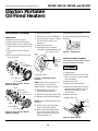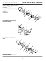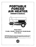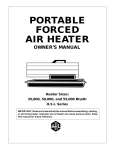
1
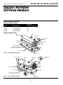
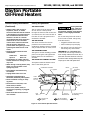
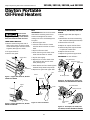
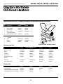
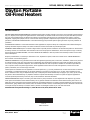
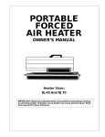
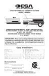
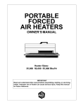
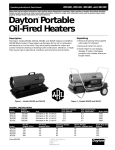
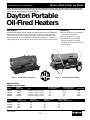
2E510E, 2E511E, 3E218E, and 3E219D
Operating Instructions & Parts Manual
Please read and save these instructions. Read carefully before attempting to assemble, install, operate or maintain the product described.
Protect yourself and others by observing all safety information. Failure to comply with instructions could result in personal injury and/or
property damage! Retain instructions for future reference.
Dayton Portable
Oil-Fired Heaters
®
Description
Unpacking
Dayton Models 2E510E, 2E511E, 3E218E, and 3E219D are 40,000 to 150,000 Btu/Hr
heaters. These heaters use only Kerosene or No. 1 fuel oil for combustion and
electricity to run the motor. They are primarily intended for indoor and outdoor
temporary heating of well-ventilated buildings under construction, alteration, or
repair. They may be used in agricultural, industrial, and commercial environments.
1. Remove all packing items supplied
with heater for shipment.
Figure 1 – Models 2E510E and 2E511E
2. Remove all items from carton.
3. Check heater for any shipping
damage. If heater is damaged,
promptly inform dealer where you
bought heater.
Figure 2 – Models 3E218E and 3E219D
ARL LOGO
®
G 004
Specifications
GENERAL SPECIFICATIONS
Model
Output
Rating Btu
Fuel
Fuel Tank Capacity
(U.S. Gallons)
2E510E
2E511E
3E218E
3E219D
40,000
60,000
110,000
150,000
Kerosene or No. 1 fuel oil
Kerosene or No. 1 fuel oil
Kerosene or No. 1 fuel oil
Kerosene or No. 1 fuel oil
3.0
5.0
9.0
13.5
Fuel Consumption
(U.S. Gallons/Hr.)
Motor RPM
0.3
0.44
0.8
1.1
1725
1725
3450
3450
Model
Hot Air
Output (CFM)
Air Pump
Pressure (PSI)
Shipping Weight
(Pounds)
Heater Weight
(Pounds - without fuel)
2E510E
2E511E
3E218E
3E219D
170
180
490
550
3.0
3.4
5.3
5.4
32
33
58
67
28
29
49
56
Form 5S1792
Printed in U.S.A.
03430
0898/157/VCPVP
®
Version B - For Reduction
G016.J
2E510E, 2E511E, 3E218E, and 3E219D
Dayton Operating Instructions and Parts Manual
Dayton Portable
Oil-Fired Heaters
®
Specifications (Continued)
ELECTRICAL SPECIFICATIONS
Model
Electrical Input
Amperage
(during normal run)
2E510E
2E511E
3E218E
3E219D
120 Volt/60 Hertz
120 Volt/60 Hertz
120 Volt/60 Hertz
120 Volt/60 Hertz
2.0
2.0
3.6
3.6
Product Identification
Handle
Hot Air
Outlet
Upper Shell
Thermostat
Knob
Lower
Shell
Fan Guard
Air Filter
End Cover
Fuel Tank
Fuel
Cap
Ignition Control Assembly
(on inside of side cover)
Side Cover
Figure 3 – Models 2E510E and 2E511E
Hot Air Outlet
Power Cord
Thermostat
Knob
Upper Shell
Fuel Cap
Fan
Guard
Lower Shell
Side Cover
Fuel
Tank
Ignition Control Assembly
(on inside of side cover)
Figure 4 – Models 3E218E and 3E219D
Power Cord
104447
2
Dayton Operating Instructions and Parts Manual
Models 2E510E, 2E511E, 3E218E, and 3E219D
General Safety Information
Make certain you read and understand
all warnings. Keep these instructions
for reference. They are your guide to
safe and proper operation of this
heater.
Safety information appears throughout these instructions. Pay close
attention to them. Below are definitions for the safety information listed
throughout this manual.
Under this heading,
installation, operating and maintenance procedures or
practices will be found that, if not
carefully followed, WILL result in IMMEDIATE serious personal injury or death.
Under this heading, installation,
operating, and maintenance procedures or practices will be found that, if
not carefully followed, COULD result
in severe personal injury or death.
Under this heading,
installation, operating, and maintenance procedures or
practices will be found that, if not carefully
followed, COULD result in minor
personal injury, product or property
IMPORTANT: Every possible circumstance
that might involve a hazard cannot be
anticipated. The warnings in this manual
and on tags or decals affixed to the unit
are therefore not all-inclusive. If a
procedure, work method, or operating
technique not specifically recommended
by Dayton is used, you must make sure it
is safe for you and others. You should
also ensure that equipment will not be
damaged or made unsafe by the operating or maintenance method you choose.
Carbon monoxide
poisoning may lead
to death! Some people are more
affected by carbon monoxide than
others. Early signs of carbon monoxide
poisoning resemble the flu, with
headaches, dizziness, and/or nausea. If
you have these signs, the heater may
not be operating properly, or the areas
may not be sufficiently ventilated. Get
fresh air at once! Have heater serviced.
d) During fueling, all fuel lines and
fuel-line connections shall be
inspected for leaks. Any leaks shall
be repaired prior to returning the
heater to service.
e) At no time shall more than one
day's supply of heater fuel be stored
inside a building in the vicinity of
the heater. Bulk fuel storage shall be
outside the structure.
Improper use of
this heater can
cause serious injury or death from
burns, fire, explosion, electrical shock,
and carbon monoxide poisoning.
f) All fuel storage shall be located a
minimum of 25 feet from heaters,
torches, welding equipment, and
similar sources of ignition (exception: the fuel reservoir integral with
the heater unit).
Make certain you read and understand
all warnings. Keep these instructions
for reference. They are your guide to
safe and proper operation of this
heater.
g) Whenever possible, fuel storage
shall be confined to areas where
floor penetrations do not permit fuel
to drip onto or be ignited by a fire at
lower elevation.
• Use only Kerosene or No. 1 fuel
oil to avoid risk of fire or explosion.
Never use gasoline, naphtha, paint
thinners, alcohol, or other highly
flammable fuels.
• Fueling
a) Personnel involved with fueling
shall be qualified and thoroughly
familiar with the manufacturer's
instructions and applicable federal,
state, and local regulations regarding the safe fueling of heating units.
b) Only the type of fuel specified on
the heater's data plate shall be used.
c) All flame, including the pilot
light, if any, shall be extinguished
and the heater allowed to cool, prior
to fueling.
h) Fuel storage shall be in accordance with the federal, state, or
local authority having jurisdiction.
• Never use heater where gasoline,
paint thinner, or other highly
flammable vapors are present.
• Follow all local ordinances and codes
when using heater.
• Use only in well-vented areas. Provide
at least three square feet of fresh,
outside air for each 100,000 Btu/Hr of
rating. This heater produces carbon
monoxide, which is listed by the
State of California as a reproductive
toxin under Proposition 65.
• Use only in places free of flammable
vapors or high dust content.
• Use only with the electrical voltage
and frequency specified on model
plate.
• Use only a three-prong, grounded
extension cord.
®
104447
3
2E510E, 2E511E, 3E218E, and 3E219D
Dayton Operating Instructions and Parts Manual
Dayton Portable
Oil-Fired Heaters
®
General Safety Information
(Continued)
Theory of Operation
Fuels
THE FUEL SYSTEM
• Heaters used in the vicinity of
tarpaulins, canvas, or similar
enclosure materials shall be located
a safe distance from such materials.
The recommended minimum safe
distance is 10 feet. It is further
recommended that these enclosure
materials be of a fire retardant
nature. These enclosure materials
shall be securely fastened to
prevent them from igniting or from
upsetting the heater due to wind
action.
The air pump forces air through the
air line. The air is then pushed
through the burner head nozzle. This
air causes fuel to lift from the tank. A
fine mist of fuel is sprayed into the
combustion chamber.
Use only Kerosene
or No. 1 fuel oil to
avoid risk of fire or explosion. Never
use gasoline, naphtha, paint thinners,
alcohol, or other highly flammable
fuels.
• Minimum heater clearances from
combustibles:
Outlet: 8 Ft.
Top: 4 Ft.
Sides: 4 Ft.
Rear: 4 Ft.
• Locate heater on a stable and level
surface while hot or running or a fire
may occur.
• When moving or storing heater, keep
heater in a level position or fuel
spillage may occur.
THE AIR SYSTEM
The motor turns the fan. The fan
pushes air into and around the
combustion chamber. This air is heated
and provides a stream of clean, hot air.
THE IGNITION SYSTEM
The ignition control assembly provides
power to the ignitor. This ignites the
fuel/air mixture in the combustion
chamber.
THE FLAME-OUT CONTROL SYSTEM
Do not use heavy fuels such as No. 2
fuel oil or No. 2 Diesel. Using heavy
fuels will result in:
• clogged fuel filter and nozzle
• carbon build-up on spark plug
• the need of non-toxic anti-icer in
fuel during very cold weather
IMPORTANT: Use a KEROSENE ONLY
container. Be sure storage container is
clean. Foreign matter such as rust, dirt, or
water will cause the flame-out control to
shut down heater. Foreign matter may also
require you to clean fuel system often.
This system causes the heater to shut
down if the flame goes out.
Combustion Chamber
Motor
Ignitor
• Keep children and animals away
from heater.
Fan
Air Pump
Air Intake
Filter
• Unplug heater when not in use.
• This heater is equipped with a
thermostat, heater may start anytime.
• Never use heater in living or sleeping areas.
Cool
Air In
Clean
Heated
Air Out
Air
Output
Filter
• Never block air inlet (rear) or air
outlet (front) of heater.
• Never move, handle, refuel, or
service a hot, operating, or pluggedin heater.
• Never attach duct work to front or
rear of heater.
Fuel
Tank
Nozzle
Fuel
Filter
Air For Fuel
System
Air Line
To Burner
Air For Combustion and Heating
Ignition Control
Assembly
Fuel
Figure 5 - Cross Section Operational View
104447
4
Dayton Operating Instructions and Parts Manual
Models 2E510E, 2E511E, 3E218E, and 3E219D
Assembly
(For Models 3E218E and 3E219D Only)
These models are furnished with
wheels and handles. Wheels, handles,
and the mounting hardware are found
in the shipping carton.
TOOLS NEEDED
• MEDIUM PHILLIPS SCREWDRIVER
• 3/8" Open or Adjustable Wrench
• Hammer
1. Slide axle through wheel support
frame. Install wheels on axle.
IMPORTANT: When installing wheels,
point extended hub of wheels toward
wheel support frame (See Figure 6).
TO START HEATER
1. Follow all ventilation and safety
information.
2. Place cap nuts on axle ends. Gently
tap with hammer to secure.
2. Locate heater to provide maximum
circulation of the heated air. Follow
all location requirements noted in
General Safety Information, page 3.
3. Place heater on wheel support
frame. Make sure air inlet end (rear)
of heater is over wheels. Line up
holes on fuel tank flange with holes
on wheel support frame.
4. Place front handle and rear handle on
top of fuel tank flange. Insert screws
through handles, fuel tank flange,
and wheel support frame. Attach nut
finger tight after inserting each screw.
Screw
Hot Air
Outlet
Air
Inlet
Fuel
Tank
Flange
Wheel Support
Frame
Ventilation
EXTENSION CORD WIRE SIZE
REQUIREMENTS
Axle
Cap Nut
Follow the minimum fresh, outside
air ventilation requirements. If proper
fresh, outside air ventilation is not
provided, carbon monoxide poisoning
can occur. Provide proper fresh,
outside air ventilation before running
heater.
Provide a fresh air opening of at least
three square feet for each 100,000
Btu/Hr rating. Provide extra fresh air if
more heaters are being used.
• a two-car garage door (16-foot-wide
opening) raised 3.5 inches
Extended
Hub
• a single-car garage door (9-footwide opening) raised 6 inches
• two, 30-inch windows raised 11
inches
Wheel
Operation
Figure 6 - Wheel and Handle Assembly,
Models 3E218E and 3E219D Only
5. Turn thermostat knob clockwise to
the HIGH position.
5. After inserting all screws, tighten
nuts firmly.
Example: A 150,000 Btu/Hr heater
requires one of the following:
Nut
4. Attach fuel cap.
6. Plug power cord of heater into
three-prong, grounded extension
cord. Extension cord must be at least
six feet long.
Front Handle
Rear Handle
3. Fill fuel tank with Kerosene or No. 1
fuel oil.
Review and
understand the
warnings in the General Safety
Information section. They are needed
to safely operate this heater. Follow
all local codes when using this heater.
• 6 to 10 feet long, use 18 AWG
rated cord.
• 11 to 100 feet long, use 16 AWG
rated cord.
• 101 to 200 feet long, use 14 AWG
rated cord.
7. Plug extension cord into standard
120 Volt/60 hertz, three-hole,
grounded outlet.
Note: Ignitor will preheat for five
seconds, then heater will start.
8. Adjust thermostat knob to the
desired setting.
Note: A cold heater may affect the
thermostat setting. Further adjustments may be needed until the heater
cycles at the desired setting. This
thermostat is a general-heating
control. It is not intended for precise
temperature control.
TO STOP HEATER
Unplug extension cord from outlet.
TO RESET HEATER
1. Unplug extension cord from outlet
and wait 10 seconds (two minutes if
heater has been running).
2. Repeat steps under To Start Heater.
®
104447
5
2E510E, 2E511E, 3E218E, and 3E219D
Dayton Operating Instructions and Parts Manual
Dayton Portable
Oil-Fired Heaters
®
Maintenance
FAN
Never service
heater while it is
plugged in, operating, or hot. Severe
burns and electrical shock can occur.
UPPER SHELL REMOVAL
1. Remove screws along each side of
heater using 5/16" nut-driver. These
screws attach upper and lower shells
together (See Figures 7 and 8).
IMPORTANT: Remove fan from motor
shaft before removing motor from
heater. The weight of the motor
resting on the fan could damage the
fan pitch.
AIR OUTPUT, AIR INTAKE, AND LINT
FILTERS
1. Remove upper shell (See Figures 7
and 8).
2. Remove filter end cover screws using
5/16" nut-driver (See Figures 10 and 11).
1. Remove upper shell.
3. Remove filter end cover.
2. Use 1/8" Allen wrench to loosen
setscrew which holds fan to motor
shaft.
4. Replace air output and lint filters.
5. Wash and dry with soap and water
or replace air intake filter.
2. Lift upper shell off.
3. Slip fan off motor shaft.
3. Remove fan guard.
4. Clean fan using a soft cloth moistened with Kerosene or solvent.
7. Replace fan guard and upper shell.
5. Dry fan thoroughly.
IMPORTANT: Do not oil filters.
Upper Shell
6. Replace filter end cover.
6. Replace fan on motor shaft. Place
fan hub flush with end of motor
shaft (See Figure 9).
Fan Guard
7. Place setscrew on flat of shaft. Tighten
setscrew firmly (40-50 inch-pounds).
8. Replace fan guard and upper shell.
Fan
Motor
Figure 7 - Upper Shell Removal, Models
2E510E and 2E511E
Air Intake Filter
Filter End Cover
Fan Guard
Lint Filter
Air Output Filter
Setscrew
Figure 10 - Air Output, Air Intake, and
Lint Filters, Models 2E510E and 2E511E
Upper
Shell
Air Intake Filter
Flush
Filter End Cover
Motor
Shaft
Lint
Filter
Fan
Guard
Figure 8 - Upper Shell Removal, Models
3E218E and 3E219D
Figure 9 - Fan Cross Section
Air Output
Filter
Fan Guard
Figure 11 - Air Output, Air Intake, and
Lint Filters, Models 3E218E and 3E219D
104447
6
Dayton Operating Instructions and Parts Manual
Models 2E510E, 2E511E, 3E218E, and 3E219D
Fuel Filter
Maintenance (Continued)
PUMP PRESSURE ADJUSTMENT
1. Remove pressure gauge plug from
filter end cover (See Figure 12).
Pressure
Gauge
2. Install accessory pressure gauge (Part
Number HA1180) (See Figure 13).
3. Start heater (See Operation, page 5).
Allow motor to reach full speed.
4. Adjust pressure. Turn relief valve to
right to increase pressure. Turn relief
valve to left to decrease pressure.
See specification chart below for
correct pressure for each model.
Model
Pump
Pressure
2E510E
2E511E
3E218E
3E219D
3.0 psi
3.4 psi
5.3 psi
5.4 psi
5. Remove pressure gauge. Replace
pressure gauge plug in filter end cover.
PRESSURE ADJUST
P
Figure 13 - Adjusting Pump Pressure
Side
Cover
Upper Fuel Line
FUEL FILTER
1. Remove side cover screws using
5/16" nut-driver.
Figure 14 - Fuel Filter Removal, Models
2E510E and 2E511E
2. Remove side cover.
Fuel Filter, Bushing, and
Lower Fuel Line
3. Pull upper fuel line off fuel filter
neck (See Figure 14).
Upper
Fuel
Line
4. Carefully pry bushing, fuel filter, and
lower fuel line (Models 3E218E and
3E219D only) out of fuel tank (See
Figure 15).
5. Wash fuel filter with clean fuel and
replace in tank.
6. Attach upper fuel line to fuel filter
neck.
7. Replace side cover.
Side
Cover
Figure 15 - Fuel Filter Removal, Models
3E218E and 3E219D
Pressure
Gauge Plug
Relief
Valve
Figure 12 - Pressure Gauge Plug
Removal
®
104447
7
2E510E, 2E511E, 3E218E, and 3E219D
Dayton Operating Instructions and Parts Manual
Dayton Portable
Oil-Fired Heaters
®
Maintenance (Continued)
IGNITOR
1. Remove upper shell and fan guard
(See page 6).
2. Remove fan (See page 6).
6. Remove combustion chamber.
Stand combustion chamber on end
with nozzle adapter bracket on top
(See Figure 17).
Ignitor Screw/Washer
Assembly
Ignitor
3. Remove 4 side cover screws with a
5/16" nut driver. Remove side cover
(See Figures 14 and 15).
4. Disconnect ignitor wires (yellow for
3E218E and 3E219D, gray for
2E510E and 2E511E) from ignition
control assembly (See Figure 16).
Pull the ignitor wires up through
the hole in the lower shell.
Ignitor
Element
Nozzle
Adapter
Bracket
Photocell
Bracket
Nozzle
Adapter
Bracket
Ignitor
Air
Line
Hose
Ignitor
Wires
Combustion
Chamber
Nozzle Adapter
Bracket Opening
Figure 17 - Ignitor Replacement
7. Remove ignitor screw with a 1/4"
nut driver. Carefully remove ignitor
from nozzle adapter bracket.
8. Carefully remove replacement
ignitor from styrofoam packing.
Photocell
Bracket
Ignition
Control
Assembly
Photocell
Assembly
Side Cover
Figure 16 - Disconnecting Ignitor Wires
from Ignition Control Assembly
13. Connect and route fuel line hose
and air line hose to nozzle adapter
assembly. See Fuel and Air Line
Replacement and Proper Routing,
page 9.
14. Replace photocell in photocell
bracket. Route wires as shown in
Figure 18, 19, or 20.
16. Replace fan guard and upper shell
(See page 6).
Do not bend or
strike ignitor
element. Handle with care.
Fuel
Line
Hose
12. Replace side cover (See Figures 14
and 15).
15. Replace fan (See page 6).
5. Disconnect fuel line hose and air
line hose. Remove photocell from
photocell bracket (See Figure 16).
Combustion
Chamber
11. Route the ignitor wires back down
through the hole in the lower shell.
Connect wires to the ignition
control assembly.
9. Carefully guide ignitor into
opening in nozzle adapter bracket.
Do not strike ignitor element.
Attach ignitor to nozzle adapter
bracket with screw using a 1/4" nut
driver (See Figure 17). Torque 8 to
15 in. lbs. Do not over torque.
10. Replace combustion chamber.
Combustion
Chamber
Burner
Strap
Photocell
Bracket
Air Line
Hose
Nozzle/
Adapter
Assembly
Fuel Line
Hose
Figure 18 - Removing Air and Fuel Line
Hoses, (40, and 60,000 Btu/Hr Models Only)
Combustion
Chamber
Burner
Strap
Photocell
Bracket
Air Line
Hose
Nozzle/
Adapter
Assembly
Fuel Line
Hose
Figure 19 - Removing Air and Fuel Line
Hoses, (110,000 Btu/Hr Model Only)
104447
8
Dayton Operating Instructions and Parts Manual
Models 2E510E, 2E511E, 3E218E, and 3E219D
Maintenance (Continued)
Combustion
Chamber
6. Carefully remove nozzle from the
nozzle adapter using 5/8" socket
wrench.
Burner
Strap
Photocell
Bracket
Air Line
Hose
5. Place plastic hex-body into vise and
lightly tighten.
Nozzle
Face
Nozzle/
Adapter
Assembly
Nozzle
Sleeve
Fuel Line
Hose
Nozzle
Figure 20 - Removing Air and Fuel Line
Hoses (150,000 Btu/Hr Model Only)
Nozzle Adapter
NOZZLE
1. Remove upper shell (See page 6).
2. Remove fan (See page 6).
3. Remove fuel and air line hoses from
nozzle assembly (See Figure 18, 19,
or 20).
4. Turn nozzle assembly 1/4 turn to
left and pull toward motor to
remove (See Figure 21).
Air Line
Fitting
Fuel Line
Fitting
Figure 22 - Nozzle and Nozzle Adapter,
All Models
7. Blow compressed air through face
of nozzle. This will free any dirt in
nozzle area.
8. Inspect nozzle sleeve for damage.
9. Replace nozzle into nozzle adapter
until nozzle seats. Tighten 1/3 turn
more using 5/8" socket wrench (4045 inch-pounds).
Burner Strap
Nozzle
Assembly
10. Attach nozzle assembly to burner
strap.
FUEL AND AIR LINE REPLACEMENT
AND PROPER ROUTING
1. Remove upper shell (see page 6).
2. Remove side cover screws using
5/16" nut driver.
3. Remove side cover.
4. Inspect fuel and air line hoses for
cracks and/or holes. If fuel line hose
is damaged, disconnect from
nozzle adapter (see Figure 18, 19,
or 20) and from fuel filter (see
page 7). If air line hose is damaged,
disconnect from nozzle adapter
(see Figure 18, 19, or 20) and from
barb fitting on pump end cover
(see Figure 23).
5. Install new air and/or fuel line.
Attach one end of air line hose to
barb fitting on pump end cover
(see Figure 23) and the other end
to nozzle adapter (see Figure 18,
19, or 20). Attach one end of fuel
line hose to fuel filter (see page 7)
and the other end to nozzle
adapter (see Figure 18, 19, or 20).
Note: Route hoses as shown in
Figure 18, 19, or 20 according to
Model. Hoses are not to touch
photocell bracket.
6. Replace side cover.
7. Replace upper shell and fan guard
(see page 6).
Pump End Cover
Barb Fitting
11. Attach fuel and airline hoses to
nozzle adapter assembly. See Fuel
and Air Line Replacement and
Proper Routing.
12. Replace fan (See page 6).
Figure 21 - Removing Nozzle Assembly,
All Models
13. Replace fan guard and upper shell.
Barb
Fitting
Air Hose
40/60,000 Btu/Hr
Models
115,000 Btu/Hr
Model
Figure 23 - Air Hose to Barb Fitting
®
104447
9
2E510E, 2E511E, 3E218E, and 3E219D
Dayton Operating Instructions and Parts Manual
Dayton Portable
Oil-Fired Heaters
®
Maintenance (Continued)
PUMP ROTOR
(Procedure if rotor is binding)
1. Remove upper shell (See page 6).
2. Remove filter end cover screws using
5/16" nut-driver (See Figures 24 and
25).
3. Remove filter end cover and air
filters.
5. Remove pump plate.
15. Reinstall insert and rotor.
6. Remove rotor, insert, and blades.
16. Perform previous steps 10 through 12.
7. Check for debris in pump. If debris
is found, blow out with compressed air.
Sandpaper
8. Install insert and rotor.
9. Check gap on rotor. Adjust to
.003"/.004" if needed (See Figure 26).
Gap Adjusting Screw
4. Remove pump plate screws using
5/16" nut-driver.
IGNITION CONTROL ASSEMBLY
.003"/.004"
Gap
Measured
With
Feeler
Gauge
Blade
Pump Plate
Air Intake Filter
Filter End Cover
Rotor
Insert
Air Output Filter
PFA/P 056B
Figure 26 - Gap Adjusting Screw
Locations
Fan Guard
Figure 24 - Rotor Location, Models
2E510E and 2E511E
NOTE: Rotate rotor one full turn to
insure the gap is .003"/.004" at
tightest position. Adjust if needed.
Blade
Pump Plate
Air Intake Filter
Filter End Cover
10. Install blades, pump plate, air
filters, and filter end cover.
11. Replace fan guard and upper shell.
12. Adjust pump pressure (See page 7).
Insert
NOTE: If rotor is still binding, proceed
as follows.
Rotor
OR-Domestic
(PROCEDURE FOR REPLACING FUSE ON
MODELS 3E218E AND 3E219D)
High Voltage!
1. Unplug heater.
Gap Adjusting Screw
Rotor
OTOR-Domestic
Figure 27 - Sanding Rotor
Blade
PFA/P 059A
Air Output Filter
Fan Guard
Figure 25 - Rotor Location, Models
3E218E and 3E219D
2. Remove side cover screws (4) using
5/16" nut-driver to expose ignition
control assembly.
3. Remove fuse cover.
4. Remove fuse from fuse clips.
5. Replace fuse with fuse of the same
type and rating (GMA-10). Do not
substitute a fuse with a higher
current rating.
6. Replace fuse cover.
7. Replace side cover.
Fuse
Clips
13. Perform steps 1 through 6 (See
page 9, Pump Rotor section).
Fuse
Cover
Fuse
14. Place fine grade sandpaper (600
grit) on flat surface. Sand rotor
lightly in “Figure 8” motion four
times (See Figure 27).
Figure 28 - Replacing Fuse
104447
10
Dayton Operating Instructions and Parts Manual
Models 2E510E, 2E511E, 3E218E, and 3E219D
Storing Transporting, or
Shipping
NOTE: If shipping, transport companies
require fuel tanks to be empty.
1. Drain fuel tank.
NOTE: Some models have drain plug on
underside of fuel tank. If so, remove drain
plug to drain all fuel. If heater does not
have drain plug, drain fuel through fuel
cap opening. Be sure all fuel is removed.
2. Replace drain plug if provided.
3. If any debris is noted in old fuel, add
1 or 2 quarts of clean kerosene to
tank, stir, and drain again. This will
prevent excess debris from clogging
filters during future use.
4. Replace fuel cap or drain plug. Properly dispose of old and dirty fuel.
Check with local automotive service
stations that recycle oil.
5. If storing, store heater in dry place.
Make sure storage place is free of dust
and corrosive fumes.
IMPORTANT: Do not store kerosene over
summer months for use during next heating season. Using old fuel could damage
heater.
Preventative Maintenance Schedule
Never service heater while it is plugged in, operating, or hot. Severe burns and electrical shock can
occur.
How Often
How To
Fuel tank
Flush every 150-200 hours of operation or as needed
Air output and
lint filters
Air intake filter
Replace every 500 hours of operation or once a year
See Storing, Transporting, or Shipping,
above
See Air Output, Air Intake, and Lint
Filters, page 6
See Air Output, Air Intake, and Lint
Filters, page 6
See Fuel Filter, page 7
See Fan, page 6
Item
Fuel filter
Fan blades
Motor
Wash and dry with soap and water every 500 hours of
operation or as needed
Clean twice a heating season or as needed
Clean every season or as needed
Not required/permanently lubricated
®
104447
11
2E510E, 2E511E, 3E218E, and 3E219D
Dayton Operating Instructions and Parts Manual
Dayton Portable
Oil-Fired Heaters
For Replacement ®Parts, Call 1-800-323-0620
24 Hours A Day - 365 Days A Year
1
Please provide following information:
-Model number
-Serial number (if any)
-Part description and number as shown in parts list
2
3
Address parts correspondence to:
Grainger Parts Operations
P.O. Box 3074
1657 Shermer Road
Northbrook, IL 60065-3074 U.S.A.
4
5
6
7
8
18
17
9
13
16
11
10
15
14
Figure 29 - Motor and Pump Assembly for
Models 2E510E and 2E511E
12
1
5
4
3
Figure 30 - Burner Head Assembly for All
Models
2
17
10
11
9
8
6
3
1
7
12
16
15
5
2
14
4
2
Figure 31 - Motor and Pump Assembly for
Models 3E218E and 3E219D
13
104447
12
Dayton Operating Instructions and Parts Manual
Models
2E510E,
and 3E219D
Models 2E510E,
2E511E, 2E511E,
3E218E, and 3E218E,
3E219D
Replacement Parts List for Motor and Pump Assembly for Models 2E510E and
2E511E - Figure 29
Ref.
No.
1
2
Description
Part
Number
Motor
102001-01
Pump Body
2E510E 2E511E
Qty.
Qty.
1
Ref.
Ref.
No.
No.
Description
Part
Number
2E510E 2E511E
Qty.
Qty.
1
11
Pressure Relief Spring
M10993-1
1
1
Plug
M22997
1
1
1
079975-02
1
—
12
079975-03
—
1
13
1/4" Diameter Steel Ball
M8940
1
3
Insert
M22009
1
1
14
Output Filter
M29612-01
1
1
4
Rotor
M22456-1
1
—
15
#10-32 x 1" Screw
*M12461-31
6
—
M22456-2
—
1
#10-32 x 11/8" Screw
M12461-32
—
6
103676-01
1
1
—
5
End Pump Cover
M29608
1
1
16
90° Elbow
6
Lint Filter
M29632
1
1
17
Blade
7
Intake Filter
M29633
1
1
8
End Cover
M29609
1
1
9
#10-32x1" Screw
*M12461-31
3
3
10
Adjusting Screw
M27694
1
1
18
M8643
4
M8643-2
—
4
#10-32 x 5/8" Screw
*FHPF3-5C
2
—
#10-32 x 3/4" Screw
*FHPF3-6C
—
2
(*) Standard hardware item, available locally.
Burner Head Assembly for All Models - Figure 30
Ref.
No.
Description
1
Nozzle
2
Nozzle Adapter
Part
Number
2E510E 2E511E 3E218E 3E219D
Qty.
Qty.
Qty.
Qty.
HA3006
1
—
—
—
100735-17
—
1
—
—
100735-19
—
—
1
—
100735-20
—
—
—
1
104056-01
1
1
—
—
104054-01
—
—
1
1
102336-01
1
1
1
1
3
Nozzle Adapter Bracket
4
Screw/Washer Assy.
104023-01
1
1
1
1
5
Ignitor
102548-01
1
1
—
—
102548-03
—
—
1
1
Replacement Parts List for Motor and Pump Assembly for Models 3E218E and
3E219D - Figure 31
Ref.
No.
Description
Part
Number
1
End Filter Cover
M16545
2
#10-32 x 1" Screw
*M12461-31
3
Intake Filter
M12179
4
Output Filter
M12244-1
5
Lint Filter
M11637
6
End Pump Cover
M50545
7
Blade
M8643
8
Rotor Pump
M22456-1
9
Rotor Insert
M22009
3E218E 3E219D
Qty.
Qty.
Ref.
Ref.
No.
No.
Description
1
1
10
Pump Body
10
10
11
#10-32 x 1/4" Screw
1
1
12
Barb Fitting
1
1
13
1
1
14
1
1
4
Part
Number
079975-02
3E218E
2E510E 3E219D
2E511E
Qty.
Qty.
1
1
2
2
M50820-02
1
1
Plug
M22997
1
1
Adjusting Screw
M27694
1
1
15
Relief Spring
M10993-1
1
1
4
16
1/4" Diameter Ball
M8940
1
1
1
1
17
Motor
102001-21
1
1
1
1
*FHPF3-5C
(*) Standard hardware item, available locally.
®
104447
13
2E510E and 3E219D
2E511E
2E510E, 2E511E, 3E218E,
Dayton Operating Instructions and Parts Manual
Dayton Portable
Oil-Fired Heaters
For Replacement ®Parts, Call 1-800-323-0620
24 Hours A Day - 365 Days a Year
Please provide following information:
-Model number
-Serial number (if any)
-Part description and number as shown in parts list
4
1
Address parts correspondence to:
Grainger Parts Operations
P.O. Box 3074
1657 Shermer Road
Northbrook, IL 60065-3074 U.S.A.
2
5
36
3
9
6
11
7
8
21
12
10
20 18
13
22
23
16
24
25
28
26
30
27
29
35
34
39
38
37
19
17
15
14
33
32
31
Figure 32 - Replacement Parts Illustration for Models 2E510E and 2E511E
104447
14
Dayton Operating Instructions and Parts Manual
Models
2E510E,
2E511E,
and 3E219D
Models 2E510E
and 2E511E
Portable 3E218E,
Oil-Fired Heaters
Replacement Parts List for Models 2E510E and 2E511E
Ref.
No.
Part
Number
Description
2E510E 2E511E
Qty.
Qty.
Ref.
No.
Description
Part
Number
2E510E 2E511E
Qty.
Qty.
1
Handle
M51104-01
1
1
23
Bushing
M50104-02
1
1
2
Upper Shell
098511-34
1
1
24
#10-16 x 3/8" Screw
* M11084-26
6
6
3
#10-16 x 3/4" Screw
* M11084-29
2
2
25
#8-32 x 3/8" Screw
* M10908-14
1
1
4
#10-16 x 1/2" Screw
* 100647-01
6
6
26
Lower Shell
098511-14
1
1
5
Combustion Chamber
098512-58
1
—
27
Rubber Airline
M50814-06
1
1
098512-50
—
1
28
Fuel Line
079973-01
1
1
29
Fuel Filter (with Bushing)
6
#6-32 x 3/8" Screw
* M10908-2
2
2
7
Photocell Bracket
103154-03
1
1
8
Photocell Assembly
M16656-23
9
Burner Assembly
†
M50876-04
1
—
M50876-05
—
1
1
1
30
Rubber Bushing
M10990-3
1
1
1
1
31
Button Plug
101695-01
1
1
* M11084-26
2
2
32
PCB Support
102349-01
5
5
103684-01
1
1
33
Ignition Control Assembly 104068-03
1
1
1
1
34
Fuel Cap (Includes Gasket) 097702-01
1
1
M51105-01
1
1
35
Fuel Tank
098513-99
1
—
Power Cord
098219-27
1
1
098513-77
—
1
Strain Relief Bushing
M11143-1
1
1
36
Shell Heat Shield
M51108-01
1
1
16
1/4-20 Hex Lock Nut
NTC-4C
2
2
37
Thermostat
104458-01
1
1
17
#10-16 x 3/8" Screw
18
Rubber Bumper
19
Side Cover
20
Motor Bracket
21
Bushing
M30865-02
2
2
∆
Wire Tie
103814-01
1
1
22
Clip Nut
M11271-8
6
6
∆
Wire Assembly
M9900-170
1
1
10
#10-16 x 3/8" Screw
11
Fan
12
Motor and Pump Assembly
13
Fan Guard
14
15
†
* M11084-26
4
4
38
Screw, #8-32 x 7/8"
M12461-18
1
1
M50631
2
2
39
Thermostat Knob
104460-01
1
1
097461-03AA
1
1
∆
Wire Clip (Secures Wires
099650-01
1
1
101205-01
1
1
of Thermostat)
(Connects Thermostat to
Ignition Control Assy)
(*) Standard hardware item, available locally.
(∆) Not shown.
(†) Not available as an assembly, see page 13.
®
104447
15
3E218E
2E510E, 2E511E, 3E218E, and 3E219D
Dayton Operating Instructions and Parts Manual
Dayton Portable
Oil-Fired Heaters
For Replacement ®Parts, Call 1-800-323-0620
24 Hours A Day - 365 Days a Year
Please provide following information:
-Model number
-Serial number (if any)
-Part description and number as shown in parts list
2
Address parts correspondence to:
Grainger Parts Operations
P.O. Box 3074
1657 Shermer Road
Northbrook, IL 60065-3074 U.S.A.
1
3
9
7
10
16
5
4
11
6
8
23
19
24
12
28
15
25
26
18
20
27
22
29
21
30
31
39
38
37
13
35
33
34
14
36
32
17
14
Figure 33 - Replacement Parts Illustration for Model 3E218E
104447
16
Dayton Operating Instructions and Parts Manual
Models
2E510E, 2E511E, 3E218E, and 3E219D
Model 3E218E
Replacement Parts List for Model 3E218E
Ref.
No.
Description
Part
Number
Ref.
Ref.
No.
No.
Qty.
Description
Description
Part Part 2E510E 2E511E
Number
Qty.
Number Qty.
Qty.
1
22
Rubber Bushing
M10990-3
1
*100647-01
8
23
Airline
M50814-03
1
Combustion Chamber
098512-54
1
24
Lower Shell
098511-163
1
Photocell Bracket
103971-01
1
25
Bushing
M50104-03
2
5
#6-32x3/8" Screw
*M10908-2
2
26
Bushing
M50104-01
2
6
Photocell Assembly
1
27
#10-16 x 1/2" Screw
*M11084-27
6
7
Burner Head Assembly
M11271-8
8
8
#10-16x1/2" Screw
9
Fan
1
Upper Shell
2
#10-16x1/2" Screw
3
4
098511-164
M16656-24
†
1
28
Clip Nut
*M11084-27
2
29
#8-32 x 3/8" Screw
097293-01
1
30
†
1
*M10908-14
1
Fuel Tank
098513-87
1
31
Fuel Cap (Includes Gasket)
097702-01
1
5
10
Motor and Pump Assembly
11
Rubber Bumper
M50631
2
32
P.C. Board Support
102349-01
12
Motor Mounting Bracket
101206-01
1
33
Strain Relief Bushing
M11143-1
1
13
Button Plug
101695-01
1
34
Power Cord
098219-24
1
14
Ignition Control Assembly
104068-02
1
35
Side Cover
M51077-09AA
1
15
1/4-20 Hex Lock Nut
NTC-4C
2
36
#10-16 x 1/2" Screw
16
Fan Guard
M51114-01
1
37
17
Drain Plug (Includes O-ring)
M27417
1
38
18
Button Plug
099213-01
1
39
Thermostat Knob
104905-01
1
19
Fuel Line
M51345-06
1
∆
Wire Clip (Secures Wires
099650-01
1
20
Fuel Filter
099743-01
1
21
Fuel Line Tube
M51151-01
1
103814-01
1
*M11084-27
4
Thermostat
097657-03
1
#6-32 x 1/4" Screw
M10908-1
2
of Thermostat)
∆
Wire Tie
(*) Standard hardware item, available locally.
(∆) Not shown.
(†) Not available as an assembly, see page 13.
®
104447
17
2E510E, 2E511E, 3E218E, and 3E219D
Dayton Operating Instructions and Parts Manual
Dayton Portable
Oil-Fired Heaters
For Replacement ®Parts, Call 1-800-323-0620
24 Hours A Day - 365 Days a Year
Please provide following information:
-Model number
-Serial number (if any)
-Part description and number as shown in parts list
2
Address parts correspondence to:
Grainger Parts Operations
P.O. Box 3074
1657 Shermer Road
Northbrook, IL 60065-3074 U.S.A.
1
3
9
7
10
4
5
16
6
8 11
23
19
24
12
28
15
25
26
18
20
27
29
22
21
30
31
39
38
37
13
35
33
34
14
36
17
32
14
Figure 34 - Replacement Parts Illustration
for Model 3E219D
104447
18
Dayton Operating Instructions and Parts Manual
Models
2E510E, 2E511E, 3E218E, and 3E219D
Model 3E219D
Replacement Parts List for Model 3E219D
Ref.
No.
Description
1
Upper Shell
2
#10-16 x 1/2" Screw
3
Part
Number
098511-164
Qty.
Ref.
No.
Description
Part
Number
Qty.
1
22
Rubber Bushing
M10990-3
1
* 100647-01
8
23
Airline
M50814-03
1
Combustion Chamber
098512-59
1
24
Lower Shell
098511-163
1
4
Photocell Bracket
099229-01
1
25
Bushing
M50104-03
2
5
#6-32 x 3/8" Screw
* M10908-2
2
26
Bushing
M50104-01
2
6
Photocell Assembly
M16656-24
1
27
#10-16 x 1/2" Screw
* M11084-27
6
7
Burner Head Assembly
†
1
28
Clip Nut
M11271-8
8
8
#10-16 x 1/2" Screw
* M11084-27
2
29
#8-32 x 3/8" Screw
9
Fan
102042-01
1
30
Fuel Tank
10
Motor and Pump Assembly
†
1
31
Fuel Cap (Includes Gasket)
097702-01
1
11
Rubber Bumper
M50631
2
32
P.C. Board Support
102349-01
5
12
Motor Mounting Bracket
101206-01
1
33
Strain Relief Bushing
M11143-1
1
13
Button Plug
101695-01
1
34
Power Cord
098219-24
1
14
Ignition Control Assembly
104068-02
1
35
Side Cover
M51077-09AA
15
1/4-20 Hex Lock Nut
NTC-4C
2
36
#10-16 x 1/2" Screw
16
Fan Guard
M51114-01
1
37
17
Drain Plug (includes O-ring)
M27417
1
18
Button Plug
099213-01
1
19
Fuel Line
M51345-06
1
20
Fuel Filter
099743-01
1
21
Fuel Line Tube
M51151-02
1
* M10908-14
1
098513-67
1
1
* M11084-27
4
Thermostat
097657-03
1
38
#6-32 x 1/4" Screw
M10908-1
2
39
Thermostat Knob
104905-01
1
∆
Wire Clip (Secures Wires
099650-01
1
103814-01
1
of Thermostat)
∆
Wire Tie
(*) Standard hardware item, available locally.
(∆) Not shown.
(†) Not available as an assembly, see page 13.
®
104447
19
2E510E, 2E511E, 3E218E, and 3E219D
Dayton Operating Instructions and Parts Manual
Dayton Portable
Oil-Fired Heaters
®
Replacement Parts List for Handle and Wheel Group Models 3E218E and 3E219D
1
Ref.
No.
Description
Part Number
3E218E
3E219D
1
Front Handle
HA2203
HA2204
1
2
Rear Handle
HA2203
HA2204
1
3
3
#10 - 24 x 1 /4"
Oval Head Screw
M12345-33
M12345-33
8
4
Wheel Support Frame
M12342-3
M12831-3
1
5
10-24 Torque Lock
Hex Nut
NTC-3C
NTC-3C
8
6
Axle
M51015-01
M16801-2
1
7
Wheel
097896-04
097896-04
2
8
Cap Nut
M28526
M28526
2
Qty.
2
3
4
8 5
6
7
Figure 35 - Handle and Wheel Assembly
Maintenance Kits
2E510E
Part Numbers for Models
2E511E
3E218E
3E219D
Ignition Control
104068-03
104068-03
104068-02
104068-02
Ignitor
102548-01
102548-01
102548-03
102548-03
Filter Kit
HA3014
HA3014
HA3017
HA3017
Nozzle Kit
HA3006
100735-17
100735-19
100735-20
Rotor/Air Pump Kit
HA3004
HA3005
HA3004
HA3004
—
—
HA2203
HA2204
Handle
Photocell
M16656-23
M16656-23
M16656-24
M16656-24
Pump Adjustment
HA3020
HA3020
HA3020
HA3020
2E510E
2E511E
3E218E
3E219D
Air Gauge Kit
HA1180
HA1180
HA1180
HA1180
Standard Wheels and Handle Kit
HA1206
HA1206
——
——
Heavy Duty Wheels and Handle Kit
HA1202
HA1202
——
——
Accessories
104447
20
Dayton Operating Instructions and Parts Manual
Models 2E510E, 2E511E, 3E218E, and 3E219D
Wiring Diagram
Ignitor
(3E218E and 3E219D Models) Yellow
(2E510E and 2E511E Models) Gray
Yellow (3E218E and 3E219D Models)
Gray (2E510E and 2E511E Models)
Ignitor
Thermostat
Red
Motor Main
Black
Black
120V (L1)
Green
Power Plug
120V/60Hz
AC Neutral (L2)
Motor Green
Ignition Control
White
White
Motor Return
Ignitor
Blue
Photocell
Photocell
Blue
Photocell
Figure 36 - Wiring Diagram for All Models
®
104447
21
2E510E, 2E511E, 3E218E, and 3E219D
Dayton Operating Instructions and Parts Manual
Dayton Portable
Oil-Fired Heaters
®
Troubleshooting Chart
Never service heater while it is plugged in, operating, or hot.
Severe burns and electrical shock can occur.
Symptom
Possible Cause(s)
Corrective Action
Motor does not start five seconds after
heater is plugged in
1. No power to heater
1. Check circuit breaker in electrical
panel
2. Thermostat setting too low
2. Turn thermostat knob to a higher
setting
High Voltage!
Motor starts and runs but heater does
not ignite
3. Bad electrical connection between
motor and ignition control assembly
or ignition control assembly and
power cord
3. Check all electrical connections. See
Wiring Diagram, page 21
4. Blown fuse on ignition control
assembly
4. See Ignition Control Assembly, page 10
5. Binding pump rotor
5. If fan does not turn freely, see Pump
Rotor, page 9
6. Defective ignition control assembly
6. Replace ignition control assembly
7. Defective motor
7. Replace Motor
1. No fuel in tank
1. Fill tank with Kerosene
2. Pump pressure incorrect
2. See Pump Pressure Adjustment, page 7
3. Dirty fuel filter
3. See Fuel Filter, page 7
4. Obstruction in nozzle assembly
4. See Nozzle, page 9
5. Water in fuel tank
5. Drain and flush fuel tank with clean
kerosene. See Storing, Transporting,
or Shipping, page 11
High Voltage!
6. Bad electrical connection between
ignitor and ignition control assembly
6. Check electrical connections. See
Wiring Diagram, page 21
7. Defective ignitor
7. Replace ignitor, see page 8
8. Defective ignition control assembly
8. Replace ignition control assembly
104447
22
Dayton Operating Instructions and Parts Manual
Models 2E510E, 2E511E, 3E218E, and 3E219D
Troubleshooting Chart (Continued)
Symptom
Possible Cause(s)
Corrective Action
Heater ignites but ignition control
assembly shuts heater off after a short
period of time
1. Pump pressure incorrect
1. See Pump Pressure Adjustment, page 7
2. Dirty air intake, air output, and/or
lint filter
2. See Air Output, Air Intake, and Lint
Filters, page 6
3. Dirty fuel filter
3. See Fuel Filter, page 7
4. Obstruction in nozzle assembly
4. See Nozzle, page 9
5. Photocell assembly not properly
installed (not seeing the flame)
5. Make sure photocell boot is properly
seated in bracket
High Voltage!
6. Dirty photocell lens
6. Clean photocell lens
7. Bad electrical connection between
photocell and ignition control
assembly
7. Check electrical connections. See
Wiring Diagram, page 21
8. Defective photocell
8. Replace photocell
9. Defective ignition control assembly
9. Replace ignition control assembly
®
104447
23
2E510E, 2E511E, 3E218E, and 3E219D
Dayton Operating Instructions and Parts Manual
Dayton Portable
Oil-Fired Heaters
®
LIMITED WARRANTY
DAYTON ONE-YEAR LIMITED WARRANTY. Portable Oil-Fired heaters, Models covered in this manual, are warranted by Dayton Electric
Mfg. Co. (Dayton) to the original user against defects in workmanship or materials under normal use for one year after date of purchase.
Any part which is determined to be defective in material or workmanship and returned to an authorized service location, as Dayton
designates, shipping costs prepaid, will be, as the exclusive remedy, repaired or replaced at Dayton’s option. For limited warranty claim
procedures, see PROMPT DISPOSITION below. This limited warranty gives purchasers specific legal rights which vary from jurisdiction to
jurisdiction.
LIMITATION OF LIABILITY. To the extent allowable under applicable law, Dayton’s liability for consequential and incidental damages is
expressly disclaimed. Dayton’s liability in all events is limited to and shall not exceed the purchase price paid.
WARRANTY DISCLAIMER. Dayton has made a diligent effort to provide product information and illustrate the products in this literature
accurately; however, such information and illustrations are for the sole purpose of identification, and do not express or imply a warranty
that the products are MERCHANTABLE, or FIT FOR A PARTICULAR PURPOSE, or that the products will necessarily conform to the illustrations or descriptions.
Except as provided below, no warranty or affirmation of fact, expressed or implied, other than as stated in the “LIMITED WARRANTY”
above is made or authorized by Dayton.
PRODUCT SUITABILITY. Many jurisdictions have codes and regulations governing sales, construction, installation, and/or use of products
for certain purposes, which may vary from those in neighboring areas. While Dayton attempts to assure that its products comply with
such codes, it cannot guarantee compliance, and cannot be responsible for how the product is installed or used. Before purchase and
use of a product, review the product applications, and all applicable national and local codes and regulations, and be sure that the
product, installation, and use will comply with them.
Certain aspects of disclaimers are not applicable to consumer products; e.g., (a) some jurisdictions do not allow the exclusion or limitation
of incidental or consequential damages, so the above limitation or exclusion may not apply to you; (b) also, some jurisdictions do not
allow a limitation on how long an implied warranty lasts, consequently the above limitation may not apply to you; and (c) by law, during
the period of this Limited Warranty, any implied warranties of implied merchantability or fitness for a particular purpose applicable to
consumer products purchased by consumers, may not be excluded or otherwise disclaimed.
PROMPT DISPOSITION. Dayton will make a good faith effort for prompt correction or other adjustment with respect to any product
which proves to be defective within limited warranty. For any product believed to be defective within limited warranty, first write or call
dealer from whom the product was purchased. Dealer will give additional directions. If unable to resolve satisfactorily, write to Dayton at
address below, giving dealer’s name, address, date, and number of dealer’s invoice, and describing the nature of the defect. Title and risk
of loss pass to buyer on delivery to common carrier. If product was damaged in transit to you, file claim with carrier.
Manufactured for Dayton Electric Mfg. Co., 5959 W. Howard St., Niles, Illinois 60714 U.S.A.
104447 01
NOT A UPC
Manufactured for Dayton Electric Mfg. Co.
Niles, Illinois 60714
®
104447-01
Rev. C
12/98
Version B - For Reduction
G016.J