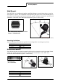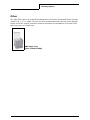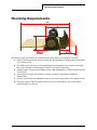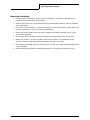
1
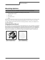
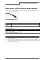
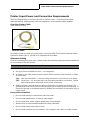
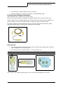
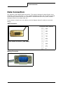
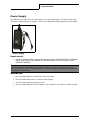
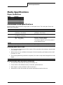
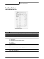
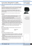
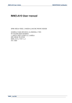
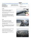
110216-002
VMP-2000
Vehicle Installation Guide
Table of Contents
General Operation and Handling Guidelines .....................................................1
Safety Guidelines ....................................................................................1
Liability Statement ..................................................................................1
Copyright...............................................................................................2
Mounting Options ........................................................................................3
Integrated Dash Mount ............................................................................3
Wall Mount.............................................................................................4
Horizontal Mount.....................................................................................4
Other ....................................................................................................5
Mounting Requirements................................................................................6
Input Power and Connection Requirements .....................................................8
Printer Input Power and Connection Requirements.......................................9
Data Connection........................................................................................ 12
Power Supply ....................................................................................... 13
Guidelines............................................................................................ 13
Ribbon Information .................................................................................... 14
Temperature ........................................................................................ 14
Printer Settings ......................................................................................... 15
Print Head Centering ............................................................................. 15
Skip Over Perforation ............................................................................ 15
Media Specifications................................................................................... 16
Paper Guidelines ................................................................................... 16
Continuous Form Specifications............................................................... 16
Form Specifications ............................................................................... 17
Radio/Bluetooth Guidelines ......................................................................... 18
Datamax-O’Neil VMP-2000 Vehicle Installation Guide
General Operation and Handling Guidelines
General Operation and Handling Guidelines
Safety Guidelines
Follow all installation, mounting, cabling and usage criteria set forth in this guide.
Liability Statement
Datamax-O’Neil does not accept liability for improperly mounted or poorly placed printers.
No Liability for Negligent Use: In no event shall Datamax-O’Neil be held liable for any
damages whatsoever (including, without limitations, damages for loss of profits, business
interruption, loss of information, or other pecuniary loss) arising out of negligence in use and
care of the product.
Radio Frequency Interference: This equipment generates and can radiate radio frequency
energy. If it is not installed and used in accordance with the user's guide, this energy may
cause harmful interference to radio and television reception.
Software: Datamax-O’Neil warrants software will function in accordance with the user guide
or written specifications provided with the software for ninety (90) days from date of
shipment. If an item or software does not function as warranted, Datamax-O’Neil will,
without charge, attempt to correct the software, the user guide, or the written specification.
For Vehicle Installations and Use
•
Air bags deflate with great force. DO NOT place objects, including installed or portable
wireless equipment, or printers in the area over the air bag or in the air bag
deployment area. If in-vehicle wireless equipment is improperly installed and the air
bag inflates, serious injury could result.
•
Position your device within easy reach. Be able to access your device without
removing your eyes from the road.
•
Do not take notes or use the device while driving. Jotting down a “to do” list or
flipping through your address book takes attention away from your primary
responsibility, driving safely.
•
Datamax-O’Neil is not responsible for damages or injuries resulting from improper
installation or use.
Ergonomic Recommendations
Caution: Even the best-designed products can be a potential source of injury/illness if used
incorrectly. To avoid or minimize risk of ergonomic injury, follow these general
recommendations. Consult with your local Health and Safety Manager to ensure that you are
meeting your company's safety programs to prevent employee(s) injury.
•
Reduce or eliminate repetitive motion
•
Maintain a neutral posture and avoid awkward positions
•
Reduce or eliminate excessive force
•
Keep objects that are used frequently within easy reach
•
Perform tasks at correct heights
•
Reduce or eliminate vibration
•
Reduce or eliminate direct pressure
•
Avoid static exertions
Datamax-O’Neil VMP-2000 Installation Guide
1
General Operation and Handling Guidelines
•
Provide adequate clearance
•
Provide a suitable working environment
•
Improve work procedures
•
Take periodic rest breaks
Care and Prevention
During operation, do not expose printer to temperatures over 50°C/122°F or under
-40°C/-40°F. In storage, do not expose printer to temperatures over 70°C/158°F or under
-20°C/-4°F.
•
Use only approved power supplies or damage may result.
•
Do not spill liquids on printer or immerse.
•
Do not attempt to service this unit. Refer all servicing to a Datamax-O’Neil authorized
service center.
Copyright
This installation guide and any examples contained herein are provided “as is” and are
subject to change without notice. Datamax-O’Neil makes no warranty of any kind with regard
to this installation guide, including, but not limited to, the implied warranties of
merchantability and fitness for a particular purpose. Datamax-O’Neil shall not be liable for
any errors or for incidental or consequential damages in connection with the furnishing,
performance, or use of this installation guide or the examples herein. This guide is
copyrighted. All rights are reserved. This guide may not, in whole or in part, be reproduced,
translated, stored in a retrieval system or transmitted in any form or by any means,
electronic, mechanical, photographic, or otherwise, without the prior written consent of
Datamax-O’Neil.
Specifications are subject to change.
COPYRIGHT © 2010, DATAMAX-O’NEIL
Datamax-O’Neil VMP-2000 Installation Guide
2
Mounting Options
Mounting Options
Note: The following instructions apply to the VMP-2000 printers only. Contact DatamaxO’Neil customer service for installation information on the VMP-1000 printers.
The following options are available for mounting the VMP printer:
•
Integrated dash mount
•
Wall mount
•
Horizontal mount
•
Other
See the brief descriptions below for the scenario which best describes your mounting needs.
Each bracket comes with vibration dampening hardware to aid in the life of your printer.
To obtain additional information about the mounting brackets, contact your salesperson or
call (949) 458-0500.
Integrated Dash Mount
The VMP-2000 can be mounted using the VMP Dashmount Kit, which includes an integrated
paper supply tray, vibration bracket and a universal cradle mount bracket. The Dashmount
Kit works where there is adequate area to support and mount the kit. The kit is designed to
either work in a vehicle or on a desktop. Please review the specific instruction sheets for
assembly and installation of the VMP-2000 Dashmount Bracket kit (part # 110092-xxx).
VMP Dashmount Bracket
(Part # 220151-100)
VMP Cradle Bracket Kit
(Part # 220153-000)
Datamax-O’Neil VMP-2000 Installation Guide
3
Mounting Options
Wall Mount
The VMP-2000 has a wallmount bracket specifically design to mount the printer to a wall or
bulk head in a vehicle. This installation is designed to pull paper from a free standing box or
can utilize the VMP paper tray. Please review the specific instruction sheets for assembly and
installation of the VMP-2000 Wallmount Bracket Kit (part # 110114-xxx).
X
0°
Y
VMP Wall Mount Vibration Bracket
(Part # 220199-000)
4’ (maximum height off of floor)
Mounting Guidelines
Use the following information as a guide for orienting and/or mounting your printer:
VMP 2000
X
0° to 15°
Y
0° to 30°
Horizontal Mount
The VMP can also be mounted horizontally utilizing the horizontal mounting bracket. Please
review the specific instruction sheets for assembly and installation of the VMP-2000
Horizontal Mount Bracket Kit (part # 110091-xxx).
X
VMP Horizontal Mount
Vibration Bracket
(Part # 220146-000)
VMP 2000
X
0° to 30°
Y
0° to 60°
Datamax-O’Neil VMP-2000 Installation Guide
4
Mounting Options
Other
The VMP-2000 paper tray is specifically designed to hold a box of standard tractor pin feed
media for 8 ½” x 11” media. The tray can be mounted underneath the wall mount bracket.
Please review the specific instruction sheet for assembly and installation of the VMP-2000
paper tray (part # 110098-xxx).
VMP Paper Tray
(Part # 220155-000)
Datamax-O’Neil VMP-2000 Installation Guide
5
Mounting Requirements
Mounting Requirements
19”
9”
3.5”
4.5”
(without
bracket)
12 - 15”
Use the following information as a guide for orienting and/or mounting your printer:
1
Before mounting the VMP printer, review the documentation supplied with the bracket
you choose to use.
2
The VMP printer can only be mounted based on the angles shown above. Mounting
the printer outside of these angles results in the printer jamming.
3
When possible, secure the hardware to the metal bulkhead or to internal metal vehicle
components.
4
Use Loctite to mount the brackets (contact Loctite for applicable installation
information).
5
Position the printer with adequate room to open the printer and for the paper to exit.
6
Place the printer near the power source (for more information, see Power Cable
Requirements on page 9).
Datamax-O’Neil VMP-2000 Installation Guide
6
Mounting Requirements
Mounting Guidelines:
•
Do not position the printer above, near, or relative to, the driver's position as to
interfere with normal driving operations.
•
Position the printer so it is protected from environmental elements such as moisture,
tools, and boxes.
•
Do not set, place, position, or put any object(s) on top of the printer, either when the
vehicle is moving, or when the vehicle is stationary.
•
Mount the printer away from the driver's head to eliminate potential injury in the
event of an accident.
•
Do not drill holes through the printer's body to permanently mount the printer.
•
Mount the printer in a secure location so that the printer is not affected by the
vehicle's vibration and the printer's hardware will not come loose.
•
Use existing mounting holes to mount the printer. Do not create new mounting holes
on the bracket.
•
Paper and humidity effect the overall performance of the printer (results may vary).
Datamax-O’Neil VMP-2000 Installation Guide
7
Input Power and Connection Requirements
Input Power and Connection Requirements
The VMP printer comes with one 12 volt DC jack cable with white collar or tag (external).
12 Volt DC Jack Cable (white)
Cable
Power applied
12 volt white cable Unit will run from vehicle power; however, it could reset if there are voltage dips and fluctua(primarily used in tions
vehicles)
Input Power Specifications
Input voltage
Maximum power consumption:
Printer is on and printing
Printer is asleep and not charging
12 - 15.5 volts
5 Amps
.05 Amps
Note: Connecting to voltage usage outside of the specifications will damage the printer.
1
The mating connection to the VMP printer is a DC plug, 2.5mm x 5.5mm x 11 or
12.0mm in length.
2
The center pin on the plug is positive (+). The center pin on the barrel is negative (-).
3
If a molded DC plug cable is purchased to connect to the printer, limit its length to 12
inches, due to voltage drops.
Datamax-O’Neil VMP-2000 Installation Guide
8
Input Power and Connection Requirements
Printer Input Power and Connection Requirements
There are several ways to connect the VMP to vehicle power — fuse box power cable,
alternate cabling, existing power harness installations, and cigarette lighter adapter.
Fuse Box Power Cable
(part # 220210-100)
Fuse Box Cable
To properly install the fuse box power cable, review the MF8i Truck Mount Extension Cable
Instruction Sheet (part # 110128-xxx) supplied with this cable.
Alternate Cabling
If you are installing your own cable, please review the following requirements and guidelines
for connecting to the VMP printer.
Note: Datamax-O’Neil accepts no liability for improperly installed cabling.
Power Cable Requirements
1
Use a minimum 16 AWG wire size — no exceptions!
2
All power to the VMP printer must be fused. Either connect to the fuse box or install
an inline fuse.
3
(2a)
Fuse box connection — the fuse rating minimum in the fuse box is 10 amps
(2b)
Inline fuse — for an inline fuse, the fuse rating should be a minimum 7 amps
and installed within three feet of the printer connection
Always connect a ground strap as close to the printer connection as possible. The
ground strap must connect to the vehicle frame (paint scraping may be required). To
ensure the ground is connected properly, validate the connection to the frame using a
power meter.
Power Cable Guidelines
•
Do not install cables or connections near wet areas.
•
Do not install cables near, or around, sharp edges.
•
Do not install wire with a smaller gauge than recommended.
•
Install a fuse as recommended and at the rating indicated.
•
Do not install cables near heat sources.
•
Do not install cables at “pinch locations” (for example, near doors or under a seat).
Datamax-O’Neil VMP-2000 Installation Guide
9
Input Power and Connection Requirements
•
At a minimum, secure cables every 12-18 inches.
•
Allow an adequate 12” loop for connector and disassembly cable.
Existing Power Harness Installation
(part # 220205-100, 220206-100, 220207-100)
The power extension cable is available in lengths of three feet, six feet, and ten feet.
If your vehicle has an existing cable power harness from a previous printer installation, it
may be used to connect to the VMP printer by using the power extension cable.
To properly install the power extension cable, review the Truck Mount Extension Cable
Instruction Sheet (part # 110128-xxx) supplied with this cable.
Power Extension Cable
Requirements:
•
The existing harness must have a fuse. See Fuse Box Power Cable (part # 220210100) on page 9 for the requirements.
•
The cable must be in good condition — no cuts, dings, etc.
Note: Datamax-O’Neil accepts no liability for improperly installed cabling.
If the end of your cable looks like these, then your existing installation may work.
Datamax-O’Neil VMP-2000 Installation Guide
10
Input Power and Connection Requirements
Once connected, use a volt meter to ensure that the center pin on the DC jack is positive (+)
12 volts and with specifications for input voltage.
Note: DO NOT connect to the printer if the center is not positive 12 volts. You will damage
the printer.
Cigarette Lighter Adapter
(part # 510116-000)
You can connect the cigarette lighter adapter to any universal 12 volt cigarette lighter plug.
If you want the printer to operate when the vehicle is turned off, make sure the cigarette
lighter adapter is powered when the vehicle power is off. If the printer does not operate from
the cigarette lighter adapter, check the fuse. You can replace the fuse with a Bussman 250
volt 7 amp fuse.
Cigarette Lighter Adapter Fuse
Cigarette Lighter Adapter
Datamax-O’Neil VMP-2000 Installation Guide
11
Data Connection
Data Connection
The VMP has a DB-9 RS232 data connection. This cable is designed to plug directly into a
handheld computer cradle dock, or other standard RS232 interface with no cabling required.
If you choose to cable connect your computer or handheld device to the printer, contact
Datamax-O’Neil for the latest cable list.
If you choose to install your own cabling, see the diagram below for cable pin outs and
design.
VMP Connector
Connector DB-9 Female
DB-9 Female Connector (VMP 2000)
Mating Connector
DB-9 Male Connector
Datamax-O’Neil VMP-2000 Installation Guide
12
Data Connection
Power Supply
The VMP can run solely from a power supply. For more information, see Input Power and
Connection Requirements on page 8. Use only the Datamax-O’Neil approved power supply.
Power Supply
Requirements
•
Use the Datamax-O’Neil recommended power supply. FAILURE TO USE A DATAMAXONEIL WILL RESULT IN DAMAGE TO THE PRINTER OR THE PRINTER WILL NOT
OPERATE PROPERLY.
Note: The operating temperature of this portable printer is 50° C. However, the operating
temperature when used with Datamax-O’Neil power supply for charging the portable
printer is limited to 35° C. Please charge the printer in a suitable location that meets this
temperature requirement.
Guidelines
•
Do not install cables or connections near wet areas.
•
Do not install cables near, or around, sharp edges.
•
Do not install cables near heat sources.
•
Do not install cables at “pinch locations” (for example, near doors or under a seat).
Datamax-O’Neil VMP-2000 Installation Guide
13
Ribbon Information
Ribbon Information
The VMP ribbon is designed to provide hundreds of pages of use. However, the ribbon is a
consumable item and should be replaced often.
•
If the printer begins jamming consistently, replace the ribbon.
•
If the printing becomes light in color on the top copy, replace the ribbon.
•
If the smear guard is damaged or lost, replace the ribbon.
Smear guard
VMP ribbon
Temperature
Although the printer is rated to print at low temperatures, ribbons are susceptible to cold
temperature. The ink in the ribbon will begin to crystallize if the temperature is below 32°F or
0°C, causing the first copy to have light print. To prevent this, the printer will automatically
enter into a low temperature printing mode when below this temperature. This mode reduces
the print speed to compensate for the temperature and the ribbon crystallization. The printer
will automatically exit the low temperature printing mode when the temperature is above
41°F or 5°C.
Datamax-O’Neil VMP-2000 Installation Guide
14
Printer Settings
Printer Settings
If you begin to see print head jams or the paper is catching under the print head when in the
‘home’ position, you may wish to change the print head centering setting or skip over
perforation.
Print Head Centering
The VMP printer has the ability to control the print head location when the media moves
across the media’s horizontal perforation. The default setting is ON when the printer is
shipped from the factory. In the default mode, the print head will move to the ‘home’ location
when moving across the perforation, which can cause problems. The head centering
command, when invoked, moves the print head to the center of the page when moving over
the perforation.
The print head centering setting can be changed using the Datamax-O’Neil software tools
(OPDI Suite or MFlash) or it can be changed in your software application.
Use firmware 5.49 or higher and check the Programmers Reference Manual for the proper
command and implementation.
Skip Over Perforation
The VMP printer has the ability to automatically control how close you print to the
perforation. Printing too close to the perforation can cause jams, paper catches, and other
problems. The default setting is OFF when the printer is shipped from the factory. In the
default mode, you will be able to print up to or on the perforation. The printer is not limited
from the factory to a particular setting due to various applications and varying form lengths.
Note: Printing close to or on the perforation is not recommended.
The skip over perforation setting can be changed using the Datamax-O’Neil software tools
(OPDI Suite or MFlash) or it can be changed in your software application.
Check the Programmers Reference Manual for the proper command and implementation.
Datamax-O’Neil VMP-2000 Installation Guide
15
Media Specifications
Media Specifications
Paper Guidelines
Media
Quantity
Original
unlimited supply
Original +1
unlimited supply
Original +2
unlimited supply
Original +3
unlimited supply
Continuous Form Specifications
Impact printers use continuous single-part or multi-part forms. The multi-part forms can
have up to four parts.
Single-Part Form
Multi-Part Form
Width
3” - 9.5”
(76.2mm - 241.3mm)
3” - 9.5”
(76.2mm - 241.3mm)
Thickness
2.6 mil - 3.9 mil
(0.065mm- 0.10mm)
Total thickness must be 0.35mm or less
Weight
64.0 - 81.4 g/m2
(55 - 70 kg/ream)
40 g/m2 chemical carbon*
(10.5 lbs. or 34 kg/ream)
* Up to four parts or, up to three parts if
crimp-fastened forms
Length
11 inches, 11.69 inches (A4), custom 11 inches, 11.69 inches (A4), custom
Copies
One (1)
Three (3)
Fastening Multi-Part Forms
•
The maximum displacement of the center of the sprocket holes between sheets shall
not exceed 0.5 mm.
•
When the forms are unfolded, the height of the horizontally perforated portion shall
be within 2.0 mm.
•
The crimping fastening method is required; four-claw crimps shall be applied on both
edges.
Note: You cannot use paper with glued edges.
Sprocket Holes and Perforation Guidelines
•
The sprocket holes shall be clearly and cleanly cut.
•
Forms shall be fan-folded at every horizontal, perforated line.
•
Both edges or each perforation shall not be torn.
•
Intersection of the horizontal and vertical perforations shall not be cut.
Datamax-O’Neil VMP-2000 Installation Guide
16
Media Specifications
Form Specifications
Paper Size and Print Area
Print Area Diagram
Symbol
Description
A
Paper Length: 11 inches (typically) (279.4 mm)/11.69 inches (A4)(297.0 mm)
B
Paper width: 3” minimum - 9.5” maximum
C
First dotline: 11.8 mm
D
Hole spacing: 12.7 mm + 0.5 mm
E
Vertical Character Alignment Tolerance:
For adjacent line:
0.3 mm maximum in bi-directional printing
For 10 lines:
1.5mm maximum
F
Maximum Print Width: 200.7 mm
G
6.35 mm
I
2 mm maximum
J
First printable line with Top of Form (TOF): Shall be set manually
K/L
K:15 mm/L: 25 mm (Where any dark print and punch holes are prohibited. Will
cause paper out condition.)
Datamax-O’Neil VMP-2000 Installation Guide
17
Radio/Bluetooth Guidelines
Radio/Bluetooth Guidelines
•
Radio communications are affected by metal and surrounding objects.
•
Consider the internal antenna location when mounting the printer. The range depends
on the orientation of the VMP printer.
•
Contact your handheld computer manufacturer for setting up the printer for Bluetooth
communications.
Datamax-O’Neil VMP-2000 Installation Guide
18