1
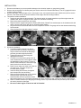
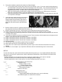
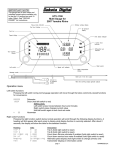
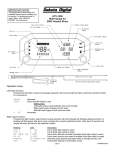
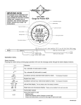
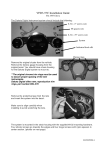
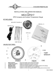
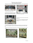
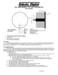
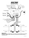
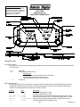
IMPORTANT NOTE! This gauge has an hour meter and odometer preset option available only for the first 1.0 engine hour and 10 miles (16km). See “ODO/HR PRESET” for instructions. UTV-1000 Multi Gauge for 2004-2006 Yamaha Rhino Operation menu Left switch functions Pressing the left switch during normal gauge operation will move through the below commonly viewed functions for convenience. 00000.0 12:00A H 0.0 Odometer Clock (hold left switch to set) Setting clock: Left switch press moves between hours and minutes Right switch press changes current value Hold left switch again to exit clock set mode Hourmeter Right switch functions Pressing the right function switch during normal operation will scroll through the following display functions. A heading will first appear after each press to display what display function is currently selected. After about 2 seconds, the display will show the data for the selected function. Heading trip A trip b srv mi(srv km) srv hr mph(KPH) tach Data a 0.0 b 0.0 s 0000 sh 000 00 mph(00 KPH) r 0000 Description Trip A (hold right switch to reset) Trip B (hold right switch to reset) Count down Service odometer if enabled (hold right switch to reset) Count down service hour meter if enabled (hold right switch to reset) Alternate speed display (hold right switch to change primary unit) Tachometer displays in information center page 1 MAN#650231:A INSTALLATION: 1. 2. 3. 4. 5. Disconnect the battery to prevent possible damage to the electrical system or gauge during install. Remove the stock gauge or indicator panel (see service manual for removal instructions). The UTV gauge will mount in this mounting location. Remove the seats, console/engine cover, front engine cover, and center floor/front drive shaft cover (refer to service manual). This allows access to sensor locations on the engine and wire routing locations. Temperature sender installation: a. Unplug the wire from the thermal switch. The thermal switch is located toward the top of the engine near the coolant outlet. NOTE: If engine is warm, allow it to cool before continuing. b. Remove the thermal switch from the engine. c. Replace with the supplied temperature sender (SEN-04-9). DO NOT use sealant tape on the threads as this will cause a poor ground, which will give an incorrect sender reading. d. Plug the wire from the thermal switch onto the temperature sender. The gauge will use the thermal switch wiring for the sender. e. Check coolant level and add coolant if needed. Oil sender installation: a. Turn the provided oil sender into the oil pressure sender hose fitting. Sealant tape may be used on this sender as the gauge provides ground through the harness. b. Tighten the sender into the fitting with appropriate wrenches. c. Cut either one of the hoses going to the oil cooler toward the front of the engine to allow the installation of the oil sender T-fixture. It doesn’t matter which hose. Have some rags handy as the hose will leak some oil. d. Place a hose clamp onto each end of the cut oil cooler hose. Two hose clamps are included with the gauge. e. Insert the fitting into the hose and tighten hose clamps onto hose and fitting. f. Remove terminal thumb nuts on oil pressure sender and put ring terminals from oil sender harness onto the terminals. Secure with terminal thumb nuts. The sender terminals don’t have a polarity so just connect one wire to each terminal. g. Route oil sender harness up to the gauge mounting location. Zip tie the harness with provided zip ties so that it will not be pinched or damaged. h. Be sure to check engine oil level and add oil if needed. page 2 MAN#650231:A 6. Fuel sender installation (optional tube sender from Dakota Digital): a. To mount the sensor you will need to drill a hole in the fuel tank. Use a 1” hole saw, and drill a hole adjacent to the small dimple on the gas tank closest to the passenger side of the vehicle. Use a fuel safe sealant and coat the supplied cork gasket to provide a leak free seal from the tank to the sensor. Secure the sensor with the supplied stainless screws. DO NOT OVER TIGHTEN THE SCREWS. b. Attach the wiring harness provided with the sender. Connect the Red wire to the POS terminal. Connect the Black wire to the NEG terminal. Connect the GREEN wire to the SEND terminal. c. Route the wire harness up to the gauge mounting location using supplied zip ties to tie the harness so that it will not be pinched or damaged. 7. Locate the stator rotation detection wire (red wire, pin 6 in the 8 pin connector coming out of CDI module located near the battery) and place the included T-tap connector onto it using a pair of pliers. This wire will be used for the tachometer signal. 8. Route the wires from the UTV gauge through the hole in the gauge opening and place gauge into opening. Secure the gauge with the three provided washers and thumb nuts. Route the yellow tach wire to the T-tap connector for the tachometer and plug into the connector. Plug the four pin connector from the oil pressure harness into the four pin connector in back of gauge. If using a separate fuel sender plug the three pin connector from the fuel sender harness into the three pin connector in the back of the gauge. Locate the three gauge connectors in the Rhino harness. These connectors will be located close to the gauge mount location on the under hood side of the dash panel. Plug the 6 pin gauge connector into the 6 pin connector on the Rhino. Plug the 4 pin gauge connector into the 4 pin connector on the Rhino Plug the 3 pin gauge connector into the 3 pin connector on the Rhino. Reconnect battery. Turn the key on and verify that the gauge functions as expected. Start engine and check for oil and water leaks. Shut off engine. If there are no oil or water leaks, reinstall the floor panels, engine covers and seats as described in the service manual. Installation is now complete. If you experience difficulties check the troubleshooting section in this manual. 9. 10. 11. 12. 13. 14. 15. 16. 17. 18. 19. 20. SETUP To enter the setup menu, press and hold the left switch while turning the key on. If your speed calibration differs from stock due to non-stock tires or gears and you will be calibrating the speedometer, press and hold the left switch while starting the engine. -Press the left switch to move through the menus or change the settings after a menu option is selected. -Hold the left switch for more than 2 seconds to scroll through options or settings -Press the right switch to select a menu option or to save a setting and go back to the menu. SETUP INFO VER U113 SP CAL 160000 MAIN SPEED UNIT AUTO Release switch to enter setup menu Information menu Displays software version Current software version Displays current speed cal value Current speed cal value Returns to info menu Speed gauge menu Select unit for speed Toggle between MPH and KPH (select unit to use for calibration) Auto calibrate speed to a marked mile or kilometer page 3 MAN#650231:A ADJUST ADJUST SRV MI (SRV KM) OFF ( OFF) 500 ( 800) …. 7500 (12000) MAIN TACH ENGINE WARN W 2250 …. W 9750 SRV HR OFF 10 … 310 MAIN Pulls up all values on speed and speed pulses in odometer Press Right switch to finish cal and save value Adjust speed cal while driving Each press of left switch toggles direction of adjustment, right switch to save and exit Sets value of service odometer set when service odometer is reset Turns off the count down service odometer (default) Sets service to 500 mi or 800 km when resetting service odometer. Service point can be set in 500 mi (800km) increments. Sets service to 7500 mi or 12000 km when resetting service odometer. Returns to info menu Tachometer gauge menu Sets number of cylinders from 1-15 (default 12 for use on alternator output) Sets RPM warning point (default 5500 RPM) Minimum warning point of 2250 RPM Warning point can be set in 250 RPM increments Maximum warning point of 9750 RPM Sets service hour value used when resetting count down service hour meter Service hour meter disabled (default) Minimum service hour set point Service hour reset point can be set in 10 hr increments Maximum service hour set point Returns to info menu GAUGES Gauge option menu VLT HI Set high voltage warning point (default 15.4V) VLT LO Set low voltage warning point (default 11.1 V) FL SND Set fuel sender used NONE No fuel sender used, fuel area will be blanked out (default) STOCK Uses stock fuel sender for Rhino DAKDIG Uses Dakota Digital sender to be installed in tank CUSTOM Uses custom sender, user must calibrate for the sender curve CAL Y (CAL N) Select CAL Y to calibrate sender EMPTY Start with empty tank, or fuel sender in empty position ADD 33 Fill fuel to 1/3 tank, press right switch to save point ADD 66 Fill fuel to 2/3 tank, press right switch to save point ADD 99 Fill fuel to full tank, press right switch to save point DONE Custom fuel calibration is complete, press right switch to go back to menu OIL LO Set low oil pressure warning point (default 9 PSI) WTR HI Set high water temp warning point and set temperature unit (default 230F) DEG F (DEG C) Select temp unit, press left switch to change, right switch to save WTR HI Select high warning, left switch to change, right switch to save MAIN Returns to info menu OPTION DIM LV OFF LVL 1 … LVL 7 DM OUT ON OFF WN OUT WN OUT NO WRN Option menu Adjust dimming point on gauge Dimming function is off Gauge will dim when light on gauge face is very low (default) 7 selectable dimming levels Gauge will dim early when more light is on gauge face Enables/disables dim output for other gauges Dim output will be high when gauge is dimming Dim output will be disabled (default) Selects which gauges provide a warn out signal on warn out wire (default all on) Gauges that provide signal out are lit up, left switch to change, right switch to save Warn output wire is disabled page 4 MAN#650231:A CLOCK± -7 SEC … 0 SEC … +7 SEC St odo Set hr MAIN DONE Adjust clock speed for accuracy Subtract 7 seconds from clock every 24 hrs No adjustment to factory clock speed (default) Add seven seconds to clock every 24 hrs Allows presetting of odometer value on initial install (not available after 10 miles / 16km) Allows presetting of hour meter value on initial install (not available after 1.0 hrs) Returns to info menu Leaves setup menu if selected ADDITIONAL SETUP NOTES: SPEED – AUTO This setup option allows calibrating to a known mile or kilometer. By default, the speed is calibrated to use the Rhino Factory speed signal. Calibration should only be needed if the factory calibration is no longer correct due to changes to tires or gearing. 1. Start with vehicle at the beginning of the marked mile or kilometer and turn the key off. 2. Start engine while holding the left switch to enter setup. 3. Select speed option in setup and select appropriate unit (if you will be calculating to a known kilometer choose KPH, else choose MPH). 4. Select the Auto option. The gauge will light all the displays and the speed display will read 5. Begin driving the mile or kilometer. The message center will read the number of pulses read from the speed signal. This value cannot be used to determine if a mile or kilometer has been driven. 6. At the end of the mile or kilometer, stop the vehicle and press the right switch to save the new speed calibration. The gauge will return to the speed setup menu. SPEED – ADJUST This setup option allows adjustment to speed while driving. By default, the speed is calibrated to use the Rhino Factory speed signal. Calibration should only be needed if the factory calibration is no longer correct due to changes to tires or gearing. 1. Start vehicle while holding the left switch to enter setup. 2. Select speed option in setup and select appropriate unit (if you will be calculating to a known kilometer choose KPH, else choose MPH). 3. Select the ADJUST option. The gauge will light all the displays and the message center will read ADJUST 4. Follow another vehicle traveling at a constant known speed. Hold the left switch to begin increasing the speed reading. To decrease the speed reading, release the switch and press and hold the switch again. 5. The direction of adjustment will change each time the switch is released. 6. When the speed has been adjusted, press the right switch to save the new speed calibration. The gauge will return to the speed setup menu. SERVICE METERS This gauge has two service meters. These are a countdown hour meter and a countdown odometer. Both service meters can be disabled, or enabled independently. This allows for setting of two individual service points, one based on engine run time, the other based on odometer. This could also allow for setting a service point on whichever service point comes first, hourly or odometer. When the setup point is reached, SERVICE DUE will scroll in the message center. Pressing either switch will clear the message until the next time the key is turned on. Once the service has been done, use the left switch to select the service meter that is due (display will show a negative value or zero). Press and hold the right switch to reset the service meter to the value set in setup. The service meter can be disabled by selecting in setup. If a new value is set for the service meter, and the meter was previously set to OFF, the service message may immediately be displayed. Reset the service meter to begin a new countdown. page 5 MAN#650231:A ODO/HR PRESET Within the first 10 miles (16 km) and 1.0 engine hours after first installing the gauge, the option is available for a ONE TIME preset of the odometer and hour meter to the reading(s) of the previous gauge. If this option is not used within the first 10 miles (16 km) or 1.0 engine hours or an incorrect reading is saved, the gauge will need to be returned to Dakota Digital for any odometer/hour meter adjustment. The procedure to preset the meters is as follows: 1. If setting odometer select st odo option in setup. If setting hour meter select set hr. 2. For odometer preset, verify that correct unit is displayed above message center. If not, turn key off to leave setup and use unit option under speed to set correct unit. NOTE: Preset MUST be done with correct unit or odometer will not be set correctly! 3. The current odometer / hour meter value is displayed with the first digit blinking 4. Press and release the left switch to change the digit. Press and release the right switch to move on to the next digit. 5. Repeat step 4 until all digits are set. After tenths digit is set, press and release the right switch. 6. Water temp display will read “”. Check the current unit (if in odo preset) and the odometer / hour meter value to make sure it is correct. If not, press and release the right switch to go back and make changes. 7. NOTE: Check the displayed odometer value VERY carefully before next step. After selecting yes, you will no longer be able to change the odometer / hour meter. 8. If the settings are all correct, press and release the left switch. Water temp display will read “”. 9. Press and release the right switch to preset the odometer / hour meter to the new value. SELECTING FUEL SENDER By default, no fuel sender is selected and the fuel display will be blank. If a fuel sender is used a fuel sender must be selected. Use the fuel sender option in the Gauges menu to select used fuel sender. The name of the fuel sender is displayed in the message center. Two numbers are also displayed on the right side of the panel. The upper number is the sender resistance in ohms at full tank. The lower number is the sender resistance in ohms at empty tank. CUSTOM FUEL SENDER SETUP If a fuel sender other than the Rhino stock fuel sender or the Dakota Digital fuel sender is used, the gauge needs to be calibrated to the new fuel sender. The custom fuel sender option in the gauges menu allows this function. 1. Begin with an empty (or near empty) fuel tank. 2. Select custom fuel sender option in gauge setup menu. 3. Use left switch to change to change to CAL Y and then press the right switch to select. 4. The gauge will light two numbers on the right side. The lower number is the current resistance of the fuel sender in ohms. The upper number is the tank percentage point currently being calibrated. 5. Four points are needed to calibrate the sender, empty, 33%, 66%, 99% (full tank). The gauge expects calibration to start at empty and move to each of these points. 6. Gauge will display EMPTY. Make sure tank is empty or sender is at empty point. Press the right switch to save point in calibration. 7. Gauge will display ADD 33. Add fuel to 1/3 tank or move sender to 1/3 full point. Press the right switch to save point in calibration. 8. Gauge will display ADD 66. Add fuel to 2/3 tank or move sender to 2/3 full point. Press the right switch to save point in calibration. 9. Gauge will display ADD 99. Add fuel to full or move sender to full point. Press the right switch to save point in calibration. 10. Gauge will display DONE. Press the right switch to finish calibration and return to gauges setup menu. OPTION – DIM OUT The dim out option allows the dim output to be turned on or off. The dim output is used if you have installed other Dakota Digital gauges and would like this gauge to also control the dimming of these gauges. If the dim out option is turned on, 12v is sent out on the dim out wire when the gauge is dimming. In this mode, the gauge will be either in dim mode or full brightness mode. If no other gauges are to be dimmed, this option can be set to off. In this mode the gauge will fade when dimming and gauge dimming will be less noticeable. page 6 MAN#650231:A TROUBLESHOOTING PROBLEM Gauge does not light up CAUSE Gauge has bad ground or power Tach always stays blank Tach wire is not connected properly Engine value set incorrectly Engine value set incorrectly Speedometer needs to be recalibrated Dim level is set to off or set too low Dim level is set too high Light sensor over left switch is covered Fuel sender resistance is too high Tach reads incorrectly Speed reads incorrectly Gauge does not dim Gauge is always dim RANGE displayed during custom fuel setup ADD FUEL is scrolled during custom fuel setup SND HI displayed during custom setup Resistance has not changed enough since previous point. Fuel sender resistance is higher than expected. SND LO displayed during custom setup Fuel sender resistance is lower than expected. PROBLEM is displayed in fuel, oil, or water display CAUSE No sender connected, or incorrect sender selected. SOLUTION Check connections to wiring harness and check wiring harness and gauge wires for pinched or broken wires. Check for good connection to alternator wire. Set Engine value to 12 for alternator (see setup) Set Engine value to 12 for alternator connection See setup for speed calibration instructions. Set dim level to higher level (see setup) Set dim level to lower level (see setup) Make sure left side of lens is not covered. Check for good connection to fuel sender and fuel sender to ground. Sender must be below 1000Ω Add fuel until next third of tank or move sender to the next third tank position. Fuel sender was started with falling resistance and now the resistance has risen. Correct fuel position or start custom programming over by turning off key. Fuel sender was started with rising resistance and now the resistance has fallen. Correct fuel position or start custom programming over by turning off key. SOLUTION Check proper connection to sender. Check for broken or pinched sensor wires. For water temp sender, check for good ground and remove any sealant tape on threads of sender. is displayed in fuel, oil or water display. Sensor wire is shorted to ground. SERVICE DUE is scrolled in the message center One of the countdown service meters has reached zero page 7 If no fuel sender is being used, set the fuel sender option to off in setup. This will blank out the fuel display. Check sensor wire harness for correct connection to sensor. Check for pinched or broken sensor wire harness. Perform service and reset service meter by holding right switch when service meter is displayed. If service meter operation is not desired, disable service meter by setting to in the setup menu. MAN#650231:A SERVICE AND REPAIR DAKOTA DIGITAL offers complete service and repair of its product line. In addition, technical consultation is available to help you work through any questions or problems you may be having installing one of our products. Please read through the Troubleshooting Guide. There, you will find the solution to most problems. Should you ever need to send the unit back for repairs, please call our technical support line, (605) 332-6513, to request a Return Merchandise Authorization number. Package the product in a good quality box along with plenty of packing material. Ship the product by UPS or insured Parcel Post. Be sure to include the RMA number on the package, and include a complete description of the problem with RMA number, your full name and address (street address preferred), and a telephone number where you can be reached during the day. Any returns for warranty work must include a copy of the dated sales receipt from your place of purchase. Send no money. We will bill you after repair. Dakota Digital 24 Month Warranty DAKOTA DIGITAL warrants to the ORIGINAL PURCHASER of this product that should it, under normal use and condition, be proven defective in material or workmanship within 24 MONTHS FROM THE DATE OF PURCHASE, such defect(s) will be repaired or replaced at Dakota Digital’s option. This warranty does not cover nor extend to damage to the vehicle’s systems, and does not cover removal or reinstallation of the product. This Warranty does not apply to any product or part thereof which in the opinion of the Company has been damaged through alteration, improper installation, mishandling, misuse, neglect, or accident. This Warranty is in lieu of all other expressed warranties or liabilities. Any implied warranties, including any implied warranty of merchantability, shall be limited to the duration of this written warranty. Any action for breach of any warranty hereunder, including any implied warranty of merchantability, must be brought within a period of 24 months from date of original purchase. No person or representative is authorized to assume, for Dakota Digital, any liability other than expressed herein in connection with the sale of this product. 4510 W. 61ST St. N., Sioux Falls, SD 57107 Phone: (605) 332-6513 FAX: (605) 339-4106 www.dakotadigital.com [email protected] ©Copyright 2009 Dakota Digital Inc. page 8 MAN#650231:A