1
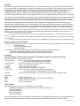
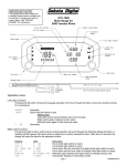
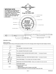
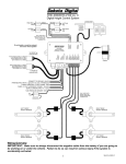
PAC-2700
ELECTRIC COOLING FAN CONTOLLER
PAC-2700
SW1
The +12V for the
controller should NOT
be taken from the same
circuit as the Fan Power
12V as this can cause
the fan to cycle on and
off.
Choose
option
below
SW2
IMPORTANT NOTE:
FAN HIGH
FAN LOW
GND
+12v
SENDER
A/C
IGNITION
FAN CONTROLLER
GAUGE
Fused battery 12V
Fan
+12V High
Fan
Low
CUSTOM
ADJUSTMENT
+12V with key ON
A/C clutch cycle switch
(+12v trigger)
Not used in
sender only
application
SENDER
Fan
+12V High
Fan
Low
Fan
Fan
High +12V Low
FAN2
FAN1
two separate fans
Fan PWR +12V
Fan PWR +12V
NOT
CONNECTED
Fan
PWR
+12V
HIGH
FAN
FAN
LOW
dual speed fan
single fan
MAN# 650264:B
Operation
The electric cooling fan controller provides a way to run up to two electric engine cooling fans or one two speed cooling
fan. (A second relay, sold separately, is required for two speed or dual fan operation). The controller monitors the engine
temperature using a dedicated sender, or a gauge and its sender. When the engine temperature goes above a user
adjustable set point, the fan is turned on with a relay. When the engine has cooled below a user selectable off
temperature, the fan is shut off. Separate on and off temperatures can be set for the high and low fan outputs. The
controller will also run the fan when the air conditioner requires, by detecting when the air conditioning clutch is engaged.
The unit can be set to keep the fan running (if the engine is hot enough) after the key is turned off. Several delay times are
available from no delay to five minutes. The display will countdown the seconds left before the fan is turned off. If the
battery voltage drops too low, the fan will be turned off and a “Lo bAt” message will display for the remainder of the time.
Settings for several gauge systems are included to make installation with a gauge easier. The included gauges are
Stewart Warner, Classic Instruments, VDO, and Autometer. If the gauge being used isn’t included, a custom calibration
option allows the system to be calibrated to any gauge with clear numerical temp markings. This is accomplished by
setting the controller to match the marks on the gauge with a few steps described in detail in the installation instructions.
IMPORTANT NOTE!!!: If using a gauge with this unit, always ensure that your gauge is working properly. If the gauge is not reading
correctly, the fan control unit will not have correct temperature information and cannot be guaranteed to properly control the fan,
possibly leading to overheating and engine damage.
If the gauge uses a two-wire temperature sender (such as Autometer full sweep) use of a dedicated Dakota Digital sender is
required.
If a gauge is not used, ONLY a Dakota Digital 300ºF sender should be used. Other senders may not give a correct reading to
the control unit.
Custom gauge calibration requires numerical marks, stock “C-NORMAL-H” type gauges cannot be accurately calibrated to.
Required components for installation:
The PAC-2700 is shipped with necessary components for use with a single fan on a gauged system. These parts include:
1
PAC-2700 module
1
RLY-3 relay with wiring harness
1
Instruction manual
For some options of the PAC-2700, additional components are required. These are listed below.
- Second RLY-3 assembly (needed for dual fan or two speed fan operation)
- 300ºF sender Dakota Digital temp sender (for operation without a gauge)
Installation
Note: Mount ONLY in vehicle cabin. Controller is not designed for engine compartment mounting.
The terminal strip on this unit has 6 connections:
1. Fan high relay
Connect to the white wire on the high fan relay assembly
(for single fan applications leave unconnected)
2. Fan low relay
Connect to the white wire on the low fan relay assembly
3. Ground
Connect to a good chassis ground
4. Power
Connect to a fused 12V battery
5. Sender
Connect to the engine temperature sender wire.
6. A/C clutch
Connect to the cycle switch on systems with air conditioning
(on systems without air conditioning leave unconnected)
7. Ignition
Connect to a circuit which has +12V only with the ignition key ON. (switched power)
Relay wiring:
White
Green
Red
Black
Connect to control unit
Connect to fused 12V battery circuit that can run cooling fan
Connect to fused 12V battery
Connect to cooling fan
Factory Presets
This controller comes preset to use a dedicated sender as follows:
Dakota Digital Sender only (no gauge, see above for 300ºF sender options)
One single speed fan
205ºF on temperature
200ºF off temperature
30 sec Fan off delay
If the factory settings don’t fit your application, you will need to go through the setup procedure on the following page. At
anytime during the setup procedure, the key may be turned off and the settings up to that point will be saved.
MAN# 650264:B
Set Up
1.
Press and hold SW2, then turn the key on.
2.
Release SW2, then press and release SW1 to move onto the next step.
3.
To select temperature scale to use, press and hold SW1 to select (Fahrenheit)
or press and hold SW2 for (Celsius). Hold the switch for longer than one sec to select. Once a temperature
scale is selected, the display will flash and go on to next setting.
4.
Display will now read
indicating low fan on temperature is to be set. Use SW1 or SW2 to select the
temperature at which the fan should turn on. Press both switches to save the setting. Display will flash once
setting is saved.
Note: SW1 increases the temperature, while SW2 decreases the temperature.
5.
Display will now read
indicating low fan off temperature is to be set. Again, use SW1 or SW2 to set the
temperature at which the fan should turn off. Press both switches to save the setting.
6.
If two fan or dual speed fan mode was previously selected, temperature settings for the high fan output are at this
point in setup for convenience. If single fan mode is set up, setup will skip high temp settings and go to step 7.
7.
6a.
Display will now read
indicating high fan on temperature is to be set. Use SW1 or SW2 to set the
temperature at which the fan should turn on. Press both switches to save the setting.
6b.
Display will now read
indicating high fan off temperature is to be set. Use SW1 or SW2 to set the
temperature and press both switches to save the setting.
Display will read
option.
Display
8.
Use SW1 or SW2 to cycle through the following options. Press both switches to select an
Option
Fan will turn off when key is turned off.
If fan was running at key off, it will continue to run for 30 seconds after key is turned off.
If fan was running at key off, it will continue to run for 45 seconds after key is turned off.
If fan was running at key off, it will continue to run for 1 minute after key is turned off.
If fan was running at key off, it will continue to run for 2 minutes after key is turned off.
If fan was running at key off, it will continue to run for 3 minutes after key is turned off.
If fan was running at key off, it will continue to run for 5 minutes after key is turned off.
Display will read
indicating fan type is to be set. Use SW1 or SW2 to select the fan type used. Press both
switches to save setting.
Display
Option
one single speed fan
(only low fan output used)
two single speed fans (high and low fan outputs both on for high temp,
& some dual spd fans only low fan output on for low temp)
one dual speed fan
(high fan output on, low fan off for high temp,
high fan off, low fan on for low temp)
Note: If two fan or dual speed are selected and high fan temp setting was not set before, setup will return to step
6 to allow temp settings to be made.
9.
Display will read
signaling to select a sender type. Press SW1 to move through
list forward, press SW2 to back up. Press both switches to save setting. The supported
senders are listed below with the display that represents each option.
Display
10.
Option
No gauge, dedicated Dakota Digital sender only
Dakota Digital individual temp gauge with sender
Dakota Digital instrument cluster with control box (ver. STR-D or later, older versions use CUS)
Stewart Warner gauge and sender
Classic gauge and sender
VDO gauge and sender
Autometer gauge and sender
Custom calibrated gauge
Custom calibration (for gauge sets not listed above)
If your gauge is not supported in one of the options above, you will need to custom calibrate the controller for your
gauge. (if CUS is selected and calibration has not been done, the calibration sequence will automatically be
started). The following is the procedure for custom calibration. If your gauge system is listed above, skip this
portion and continue at step 11.
MAN# 650264:B
Custom Calibration
Note 1: If your engine is warm you may need to disconnect the wire from your sender in order get to the lower
points on the gauge.
Note 2: If the key is turned off in custom setup, the previous gauge setting will be used and the custom gauge will
not be saved.
Note 3: If your gauge does not have defined ticks with numerical temp readings, it is highly recommended to use
a dedicated sender as calibration to the gauge is very inaccurate or impossible without temp markings.
CC1. Select
in Step 9 above. Display will read
.
CC2. Turn the potentiometer on the lower right corner of the unit (marked CUSTOM ADJUSTMENT) with a
small flat screw driver. While doing so, watch your temp gauge and line up the needle with the lowest
temperature tick on the gauge. Custom gauge must be calibrated starting at cold temperatures and
moving to hot temperatures.
Note: Turning potentiometer clockwise increases temperature reading.
CC3. Once the gauge is set to a tick, press SW1 or SW2. A temperature reading will appear on the display.
Scroll to the temp reading that matches the tick temperature reading on the gauge using SW1 to increase
.
and SW2 to decrease. Press both buttons to save the number. Display will again read
CC4. Repeat steps CC2 and CC3 with the next lowest tick on gauge until all the ticks on your gauge have been
to stop setting points if there
set. (up to 6 but no less than 4 points). Press both SW1 and SW2 at
are less than 6 points on your gauge. If there are more than 6 points on your gauge, select points over
the full range of the gauge (cold to hot). This will give a better match to your gauge.
11.
to indicate set up is complete. The unit now has been set up. If the wiring and setup have
Unit will flash
been properly completed the unit should begin normal operation at this point.
Resetting Factory presets
This procedure will return the device to the original factory presets and clear custom calibration settings.
NOTE: Calibration data for the custom gauge setup will be lost when reset to factory presets.
1. Turn key off.
2. Press and hold SW1 and SW2 and turn key on.
3. Display will read
for reset
4. Display will flash
to indicate unit is reset. Factory reset values are listed at the
beginning of the setup portion of this manual.
Checking set up (diagnostic mode)
This unit comes with a feature to allow you to mimic normal operating temperatures using the
adjustment pot. This can allow you to test the installation before ever starting the engine. Just
follow these steps.
1.
Turn the key on.
2.
Press SW1 and SW2 at the same time and hold. A number representing the temperature will come up on the
display. This number will blink once to indicate that the unit has entered diagnostic mode. SW1 and SW2 may
now be released and the unit will remain in diagnostic mode until the key is turned off.
3.
Adjust the potentiometer on the left side of the unit while watching the display and listening for the fan. The fan
should start when the display reads hotter than the set ON temp. It should again shut off when the display reads
lower than the OFF temp.
4.
You may also look at your water temperature gauge (if unit is using a gauge) and compare the temperature
reading of the unit to the gauge. The temperatures should be within a few degrees. If not, the wrong gauge may
be selected in the setup routine. Go through setup again by turning off the ignition, pressing and holding SW2 and
turning ignition back on. If a selection cannot be found that closely matches your gauge you may have to custom
calibrate to your gauge. (see step 10 in setup)
Checking the current reading
The current temperature reading can be displayed on the unit at anytime during normal operation without going into the
diagnostic mode. Simply press and hold SW1 while the key is on and the PAC-2700 is not in setup or diagnostic mode.
The current temperature will be shown on the display until the SW1 is released.
MAN# 650264:B
TROUBLESHOOTING
PROBLEM
Display reads “Er0”
(lost memory)
Display reads “Er1”
(shorted sender)
CAUSE
Setup memory lost, unit needs to be
recalibrated
Wrong gauge selected
SOLUTION
Go through setup procedure, (see setup in this manual)
Gauge disconnected from sender
(gauge option only)
Reconnect gauge to sender
Sender is shorted
Display reads “Er2”
(open sender)
Display reads “Er3”
Display reads “bAt”
when attempting to go
into setup
Display alternates
between “Lo” and “bAt”
Fan turns on late, or
not at all
Fan runs constantly
Select proper gauge in setup or use custom cal if
needed
Check sender wire for short to ground, look for pinched
sender wire or bare connection touching ground
Unit not connected to sender
Wrong gauge selected
Connect SENDER terminal on unit to sender circuit
Use setup to select proper gauge, or use custom cal if
needed
Sender not connected
Reconnect wire to sender
Unit not connected to sender
Setup data is out of valid range
+12v terminal does not have
constant power
Connect SENDER terminal on unit to sender circuit
Go through setup again, custom cal may be incorrect
Connect +12v terminal to fused battery connection. This
terminal should have constant power at all times.
Battery voltage dropped too low
during key off extended fan on time
Ensure battery is fully charged. Check and replace weak
battery. Shorten fan delay time to prevent excessive
battery drain.
With key on, hold SW1, if the display doesn’t show a
temperature after a few seconds, check battery and
ground connections.
Unit has no power
Broken/shorted wire to sender
Check wire to sender for breaks or shorts and repair.
Wrong gauge is selected
(gauge setup)
Hold SW1, if temperature read is lower than expected or
doesn’t match gauge, redo setup.
Wrong sender used
(for no gauge setup)
For sender only applications ONLY a Dakota Digital
300ºF sender can be used. Other senders may not give
a correct temperature reading.
On temperature in setup is too high
Hold SW1, if temperature read is above the desired on
temperature, and fan is not running, redo setup.
Fan not connected properly
Remove fan output from unit and short wire to ground. If
fan does not run, check relay and fan connections.
Alternator overcharging
(Analog gauge applications only)
Controller has an error
Use a voltmeter to measure the voltage at the battery
while the engine is running. If this voltage is above 15v
the unit may turn the fan on later than expected. Either
correct overcharging problem or set on temp lower to
compensate.
Check display for error message
Fan off temp too low
Increase off temp in setup
Broken/shorted wire to sender
Check wire to sender for breaks or shorts and repair.
Wrong gauge is selected
Select appropriate gauge in setup, or custom calibrate if
your gauge is not supported.
MAN# 650264:B
TROUBLESHOOTING (continued)
PROBLEM
Custom gauge setup
displays “Err” and
returns to “Snd” setup
option
Fans cycle on-off
especially when engine
temp is close to
On/off set point
CAUSE
Not enough points used
SOLUTION
Make sure that at least 4 points of gauge are set
Points not input in correct order
Set gauge points in order from cold points to hot points
Point entered twice
+12v for controller taken from same
circuit as the fan power +12V (green
wire on relays)
Each point set must be different that the point before it
Connect the +12V for the controller to a different circuit
separate from the circuit connected to fan relays.
SERVICE AND REPAIR
DAKOTA DIGITAL offers complete service and repair of its product line. In addition, technical consultation is available to help you work through any questions or
problems you may be having installing one of our products. Please read through the Troubleshooting Guide. There, you will find the solution to most problems.
Should you ever need to send the unit back for repairs, please call our technical support line, (605) 332-6513, to request a Return Merchandise Authorization
number. Package the product in a good quality box along with plenty of packing material. Ship the product by UPS or insured Parcel Post. Be sure to include the RMA
number on the package, and include a complete description of the problem with RMA number, your full name and address (street address preferred), and a telephone number
where you can be reached during the day. Any returns for warranty work must include a copy of the dated sales receipt from your place of purchase. Send no money. We will
bill you after repair.
Dakota Digital 24 Month Warranty
DAKOTA DIGITAL warrants to the ORIGINAL PURCHASER of this product that should it, under normal use and condition, be proven defective in material or
workmanship within 24 MONTHS FROM THE DATE OF PURCHASE, such defect(s) will be repaired or replaced at Dakota Digital’s option.
This warranty does not cover nor extend to damage to the vehicle’s systems, and does not cover removal or reinstallation of the product. This Warranty does not
apply to any product or part thereof which in the opinion of the Company has been damaged through alteration, improper installation, mishandling, misuse, neglect, or
accident.
This Warranty is in lieu of all other expressed warranties or liabilities. Any implied warranties, including any implied warranty of merchantability, shall be limited to
the duration of this written warranty. Any action for breach of any warranty hereunder, including any implied warranty of merchantability, must be brought within a period of 24
months from date of original purchase. No person or representative is authorized to assume, for Dakota Digital, any liability other than expressed herein in connection with
the sale of this product.
4510 W. 61ST St. N., Sioux Falls, SD 57107
Phone: (605) 332-6513 FAX: (605) 339-4106
www.dakotadigital.com
[email protected]
©Copyright 2010 Dakota Digital Inc.
MAN# 650264:B