1
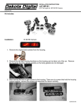
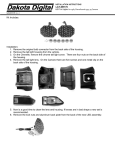
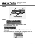
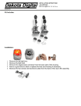
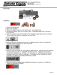
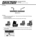
INSTALLATION INSTRUCTIONS
LAT-NR100
LED Tail Lights for 1967-68 SS and 1970-73 Camaro.
MAN# 650153
Kit Includes:
Installation:
67-68 SS Camaro
70-73 Camaro
1. Remove the tail light assembly from the vehicle by removing the original bulb sockets from the
housing. Then remove the housing hardware so it can be removed from the car. Remove the
housings from the vehicle carefully so the housing to body gaskets are not damaged.
2. Next remove the lens.
The 67-68 Camaro has six screws that hold the housing halves together which will need to be
removed to gain access to lens.
The 70-73 Camaro lens has tabs locking it into the plastic housing. Pry the tabs gently with a
screwdriver to remove lens.
MAN# 650153
3. Now is a good time to clean the lens and housing. If lenses are in bad shape a new set is
recommended.
If you are installing this kit into a 67-68 Camaro skip ahead to step 5. For the 70-73 Camaro,
some of the hardware will need to be changed out for proper mounting bracket
4. Changing the installed 67-68 mount bracket to the 70-73 mounting bracket.
a. Note how the current assembly is attached and notice how the wires are routed for reassembly. ENSURE THE WIRES ARE NOT PINCHED IN THE NEW ASSEMBLY.
b. Remove the screw at the back of the LED assembly; it is a 5/8” 6-32 machine screw.
This will remove the mounting bracket that will need to be changed.
c. Locate the supplied longer mount bracket and reattach using the shorter supplied 1/2”
6-32 machine screw. The shorter screw must be used since the taller mount is thinner.
Tighten the screw down in the center of the slot. The LED assembly can be moved up
or down to adjust the height of the light.
d. Note: NOT FOLLOWING THESE STEPS CAN DAMAGE THE CIRCUIT BOARD!
1967-1968 Camaro mount
1970-1973 Camaro mount
1970-1973 Camaro LED Assembly
5. Remove the mounting plate from the bottom of the assembly which is attached with two 3/8” 632 machine screws.
6. Pass the wires through the tail light housing where the original bulb and socket were.
MAN# 650153
7. Feed the wires through the larger hole in the mounting plate. Guide the mounting plate to the
bottom of the housing. The flat side of the mounting plate should be down and the side with
the slight raised center should go up into the housing. This will align the mount in the original
housing.
8. Now hold the LED assembly so that it is centered over the hole where the original bulb was
located and align the mounting plate from the bottom with the slot in the housing. The screw
holes should be lined up.
9. Screw the mounting plate into the assembly mount using the two previously removed 3/8” 6-32
screws.
10. Install the lens and/or re-assemble the tail light housing, insuring all gaskets are intact and in
place. Install the tail light housing back into the vehicle. You are now ready to wire the LED
assembly into the vehicle tail light harness.
MAN# 650153
11. Start by cutting off the existing light socket as it will not be used. Do not strip wires. Trim the
wires from LED assembly to appropriate length once mounted, making sure wires are routed
cleanly and securely.
12. Use the supplied moisture resistant pigtail connectors* to attach the wires from the new LED
assembly to the existing vehicle harness. Insert appropriate wire from vehicle harness and
mating LED assembly wire into a connector and crimp following instructions below.
*For the best connection, soldering is recommended. But to simplify installation, the supplied connectors will
provide a fast weather resistant connection.
The correct crimp method for the supplied connectors is:
1.) Insert UNSTRIPPED wires from both LED assembly and vehicle harness into the connector
and ensure they are all they way in by observing the clear bottom of the connector to see the
wires are touching the end.
2.) Use pliers to push the blue cap down flush with the edge of the clear body, completing the
connection. The connection will only be correct if pressed firmly down with pliers.
Attach to metal bolt or screw
for Ground connection with
metal housings
OR
GREEN wire
from LED
assembly
BROWN wire
from LED
assembly
BLACK wire
from LED
assembly
Tail Light wire
from vehicle
harness
Turn Signal wire
from vehicle
harness
Taillight
Driver’s Turn
Passenger’s Turn
Ground
LED wires
Brown
Green
Green
Black
Ground wire from vehicle
harness
with plastic housings
BLACK wire
from LED
assembly
Vehicle harness
Brown
Green
Yellow
Chassis or body
13. Repeat for the other side.
14. Test the tail lights, brake lights, and turn signals. If the turn signals do not flash you will need
to upgrade your flasher. If you are replacing only the rear turn signals you should be able to
use a heavy duty electronic flasher from your local parts store. If you are replacing both front
and rear or do not have front bulbs you will need a no-load flasher, Dakota Digital part number
LAT-NLF.
SERVICE AND REPAIR
DAKOTA DIGITAL offers complete service and repair of its product line. In addition, technical consultation is available to help you work through any questions or problems you may be
having installing one of our units.
Should you ever need to send the unit back for repairs, please package the product in a good quality box along with plenty of packing material. Ship the product by UPS or insured Parcel
Post. Be sure to include a complete description of the problem, your full name and address (street address preferred), and a telephone number where you can be reached during the day.
An authorization number for products being returned for repair is needed. We will contact you if any repair charges exist. Any returns for warranty work must include a copy of the dated
invoice or bill of sale.
LED LIGHTING LIMITED LIFETIME WARRANTY
DAKOTA DIGITAL (the Company) warrants to the ORIGINAL PURCHASER of this LED Lighting product under normal use and condition, be proven defective in material or
workmanship DURING THE LIFETIME OF THE CAR IN WHICH IT WAS ORIGINALLY INSTALLED, such defect(s) will be repaired or replaced (at the Company’s option) without charge for parts
or labor directly related to repairs of the defect(s).
To obtain repair or replacement within the terms of this Warranty, the product is to be delivered with proof of warranty coverage (e.g. dated bill of sale), specification of
defects, transportation prepaid, to the factory. This Warranty is valid for the original purchaser only and may not be transferred.
This warranty does not cover damage to vehicle electrical system. This Warranty does not apply to any product or part thereof which in the opinion of the Company has been
damaged through alteration, improper installation, mishandling, misuse, neglect, or accident.
This Warranty is in lieu of all other express warranties or liabilities. ANY IMPLIED WARRANTIES, INCLUDING ANY IMPLIED WARRANTY OF MERCHANTABLITY, SHALL BE
LIMITED TO THE DURATION OF THIS WRITTEN WARRANTY. ANY ACTION FOR BREACH OF ANY WARRANTY HEREUNDER INCLUDING ANY IMPLIED WARRANTY OF MERCHANTABLITY MUST
BE BROUGHT WITHIN A PERIOD OF 30 MONTHS FROM DATE OF ORIGINAL PURCHASE. IN NO CASE SHALL THE COMPANY BE LIABLE FOR ANY CONSEQUENTIAL OR INCIDENTAL DAMAGES
FOR BREACH OF THIS OR ANY OTHER WARRANTY, EXPRESSED OR IMPLIED, WHATSOEVER. No person or representative is authorized to assume for the Company any liability other that
expressed herein in connection with the sale of this product.
FOR SERVICE SEND TO: DAKOTA DIGITAL, 4510 W. 61st ST N., SIOUX FALLS, SD 57107 USA (800) 852-3228
Email us at [email protected]
MAN# 650153