1
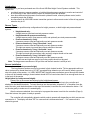
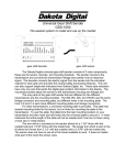
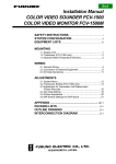
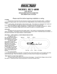
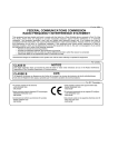
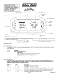
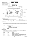
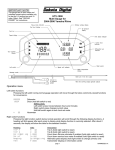
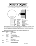
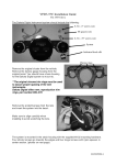
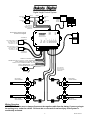
DHC-2000/DHC-2100 rev. C
Digital Height Control System
Right Rear
Bag
Left Rear
Bag
GREEN
BROWN
SEN-03-1
SEN-03-1
PURPLE
ORANGE
SEN-03-1
Left Front
Bag
SEN-03-1
Right Front
Bag
OPTIONAL
REMOTE
CONTROL
ANTENNA
STATUS LIGHT
RIGHT FRONT DOWN (+) GREEN
LEFT FRONT DOWN (+) RED
RIGHT FRONT UP (+) BLACK
LEFT FRONT UP (+) WHITE
MAIN
POWER
HARNESS
AIR
SOLENOID
HARNESS
To FRONT air
solenoid block
DISPLAY
HARNESS
DHC-2000
DIGITAL HEIGHT
CONTROL SYSTEM
REMOTE
ANTENNA
Dakota Digital
RED (+)
GREEN (L-F)
BLACK (-)
RED (+)
GREEN (R-F)
BLACK (-)
RED (+)
GREEN (L-R)
BLACK (-)
RED (+)
GREEN (R-R)
BLACK (-)
Do not bundle or route the solenoid
and sensor wires together!
PRESSURE
SENDER
HARNESS
ONLY USED WITH
PRESSURE ONLY OR
HEIGHT-PRESSURE
COMBINATION
Display
RIGHT REAR DOWN (+) GREEN
LEFT REAR DOWN (+) RED
RIGHT REAR UP (+) BLACK
LEFT REAR UP (+) WHITE
To REAR air
solenoid block
CONNECT TO GROUND BLACK
PARK/NEUTRAL INPUT (-) [ground if not used] WHITE/BLUE
FUSED, CONSTANT 12 VOLT POWER RED
FUSED, 12 VOLT ACCESSORY POWER YELLOW
DISPLAY DIMMING INPUT (+) BLUE
TANK PRESSURE SENDER GRAY
Air
Tank
ONLY USED WITH
HEIGHT ONLY OR
HEIGHT-PRESSURE
COMBINATION
SEN-03-5
GROUND
LEFT FRONT
HEIGHT SENSOR
RIGHT REAR
HEIGHT SENSOR
RIGHT FRONT
HEIGHT SENSOR
LEFT REAR
HEIGHT SENSOR
Wiring Overview
IMPORTANT: Make sure to always disconnect the negative cable from the battery if you are going to
be working on or under the vehicle. Failure to do so can result in serious injury if the system is
accidentally activated.
1
MAN# 650031C
Introduction
Congratulations, you have purchased one of the finest AIR-Ride Height Control Systems available. This
system can:
• use height sensors, pressure senders, or both height and pressure senders to monitor and control of
all four corners of the vehicle with the option of monitoring the tank pressure.
• have three different height presets for automatic up/down control, manual up/down control, and to
completely empty the air bags.
• be connected to an ARR-2000 remote transmitter system to allow remote control of the air bag system
when the key is off.
Sensor Types
Here are the possible setup configurations for height, pressure, or both height and pressure based
systems:
• Height based only:
4 height sensors used and one tank pressure sender.
• Height based with pressure monitoring:
4 height sensors used, 4 bag sensors used, and optionally one tank pressure sender.
• Pressure based only, 4 bag:
4 pressure sensors used and optionally one tank pressure sender.
• Pressure based only, 3 bag (2 front and 1 rear):
3 pressure sensors used and optionally one tank pressure sender.
The right rear sensor input and relay outputs should not be used.
• Pressure based only, 2 bag (1 front and 1 rear):
2 pressure sensors used and optionally one tank pressure sender.
The right front and right rear sensor input and relay outputs should not be used.
• Pressure based only, 2 bag (1 left and 1 right):
2 pressure sensors used and optionally one tank pressure sender.
The left rear and right rear sensor input relay outputs should not be used.
Note: The bag pressure senders are 150 psi units and the tank sender is a 400 psi unit.
Sensor Installation
Pressure based (or both pressure/height)
The bag pressure senders need to be mounted in their desired location T’d into appropriate airline or
valve; make sure to thread them into a 1/8” NPT grounded fitting otherwise you will need to attach a ground
wire to the body of the sender. It is VERY IMPORTANT that the pressure senders ground through the threads
or there will be unstable readings, thread sealant should NOT be used unless there is an extra ground wire run
to the body of the sender
Height based (or both pressure/height):
Please refer to the manual accompanying the height based sensor.
Once the height sensors are mounted, the cables will need to be routed up to the controller and
attached to the labeled terminals. To insert the wires into the terminals, strip about ¼” of insulation from the
end of the wire, push the button down on the top of the terminal, insert the wire, and release the button. Pull
on the wire gently to make sure it is seated tightly.
After the wires are attached, the next step is to program the sensor travel into the controller (Page 4).
Once that is done, the system is ready to operate.
The controller will automatically determine which mode to operate with depending on which sensors are
connected to it. The display will show “EE” for a sensor that is disconnected and “- -“ for a sensor that is
shorted to ground.
2
MAN# 650031C
OPERATION / PROGRAMMING
The auto height control system is active when both the large red power wire and the yellow accessory power
wire are on. When the accessory power is off the display and height control will shut down to prevent draining
the battery.
The display unit has a 2 line, full character display with three switches on the left side and four switches on the
right side. The left side switches select the presets. The right side switches allow manual control, change the
display, and are used for setup.
Preset Select Switches
Manual Control / Setup Switches
MANUAL RAISE
HI AUTO
MID AUTO
LO AUTO
LEFT SWITCH
RIGHT SWITCH
MANUAL LOWER
Changing the display:
Pressing the left and right manual control switches at the same time will toggle the display between the height
values, the tank pressure, and the corner pressures.
Manual control:
When manual control is active, the set of 4 manual control switches will be lit brightly. The function of these
switches are as follows:
• Pressing the left or right switch will change which readings on the display that are
highlighted(all four, front two, rear two, or individual)
• Pressing the top switch will raise the corners that are highlighted
• Pressing the bottom switch will lower the corners that are highlighted
The Park/Neutral input (white/blue wire) is used to disable manual down when the vehicle is in gear. This
should be connected to a vehicle wire that is grounded when the vehicle is in park or neutral (or to a Dakota
Digital GSS-2000 output) where required by law. To disable this feature connect the white/blue wire directly to
ground.
If the down switch is pressed and the white/blue wire is not grounded the display will show “LOCK”.
Auto control:
The three switches on the left select the three preset heights: High, Medium, and Low. When one of the auto
presets are active, that switch will be lit brightly. To select one of the presets, press the corresponding button.
To change any of the 3 presets:
• Manually adjust the height and then press and hold the button for that preset (H, M, or L) for about 4
seconds. The display will display “SET” and store the new setting.
You can also do a bag dump by pressing the H and L switches at the same time for about 4 seconds. This will
do a controlled dump to about 3-5% height.
Tank Warning:
The tank pressure has a user adjustable low warning point. If the tank pressure drops below the warning point
the display will automatically switch to displaying the tank pressure and the number will flash.
3
MAN# 650031C
Manual Control / Setup Switches
SETUP UP
SETUP SELECT
SETUP DOWN
Setup Menus:
To enter the setup mode, press and hold the Setup Select Switch while turning the key on. Use the top and
bottom Setup Switches to scroll up and down through the menus. Use the Setup Select switch to select a
menu item.
The menus are:
DONE
exit the setup routine
REM
Remote system setup (operation mode and transmitter programming)
SENSR
Sensor programming (adjusting for mechanical arm travel)
SPEED
Solenoid control speed (to slow down fast air systems)
WARN
Tank warning point setup
KEYON
Select operation mode when key is turned on.
ADVNC
Advanced control setup options.
Programming sensor travel:
1. Begin with the key off and then hold the left Setup Select Switch in while turning the key on. The display
will show (“CODE” “AC44B”, aluminum control case)( “CODE” “AC48”, plastic control case).
2. Release the switch. The display will show “SETUP” “DONE”.
3. Press the up or down Setup Switch until “SENSR” is displayed.
4. Press and release the left Setup Select Switch switch. The display will toggle between “DUMP” “ALL” and
“DONE” “PRS M”.
5. Use the down Setup Switch to dump the air from all of the bags and then press the M switch (medium
switch on left side of display)
6. The display will now toggle between showing a number for each of the four corners, “RAISE” “ALL”, and
“DONE” “PRS M”. Use the up Setup Switch to raise all bags to their full height. The numbers will begin
increasing until they reach 100 and then it will stay at 100. If any bag does not get to 100 then that sensor
may need adjustment to increase the arm travel.
7. Press the left Setup Select Switch to control front only, the right Setup Select Switch to control rear only, or
both left and right Setup Select Switches together to control all 4 corners.
8. When all four corners are fully raised, press the M switch(medium switch on left side of display)
9. The display will show “SETUP” “DONE”. Press the Setup Select Switch or turn the key off to exit.
Changing the key on mode:
When the key is turned on, the system can be set up to go to back to the last mode it was in before the key
was turned off, it can always start up in the “M” (medium) auto mode, it can always do an auto raise to the “M”
setting and then turn the auto mode off, or it can always start with the auto mode off.
1. Begin with the key off and then hold the left Setup Select Switch in while turning the key on. The display
will show (“CODE” “AC44B”, aluminum control case)( “CODE” “AC48”, plastic control case).
2. Release the switch. The display will show “SETUP” “DONE”.
3. Press the up or down Setup Switches until “KEYON” is displayed.
4. Press and release the switch. The display will show “KEYON” and the current setting
(“LAST”, “M”, “M OFF”, or “OFF”).
5. Press the up or down Setup Switches to change the setting. When the desired setting is shown, press and
release the left Setup Select Switch.
6. The display will show “SETUP” “DONE”. Press the left switch or turn the key off to exit.
4
MAN# 650031C
Changing the output speed:
The output speed can be used to slow down systems with large air lines or high pressure tanks so that
the system will operate more reliably and stop at the desired height with minimal overshoot.
1. Begin with the key off and then hold the left Setup Select Switch in while turning the key on. The display
will show (“CODE” “AC44B”, aluminum control case)( “CODE” “AC48”, plastic control case).
2. Release the switch. The display will show “SETUP” “DONE”.
3. Press the up or down Setup Switch until “SPEED” is displayed.
4. Press and release the left Setup Select Switch. The display will show “FRONT” “SPEED” and the current
speed setting.
5. Use the up or down Setup Switch to change the speed number from 1 to 15 with 15 being the slowest.
When the desired value is shown press and release the left Setup Select Switch.
6. The display will now show “REAR” “SPEED” along the current setting for the rear bags.
7. Use the up or down Setup Switch to change the value and press and release the left Setup Select Switch
when done.
8. The display will show “SETUP” “DONE”. Press the left Setup Select Switch or turn the key off to exit.
Changing the tank warning point:
The tank warning point can be adjusted from 0 to 248 psi. When the tank pressure drops below this
point the tank reading will flash and the display will automatically switch to the tank pressure display. If the
tank pressure sender is disconnected this is disabled.
1. Begin with the key off and then hold the left Setup Select Switch in while turning the key on. The display
will show (“CODE” “AC44B”, aluminum control case)( “CODE” “AC48”, plastic control case).
2. Release the switch. The display will show “SETUP” “DONE”.
3. Press the up or down Setup Switch until “WARN” is displayed.
4. Press and release the switch. The display will show “TANK” “WARN” and the current set point.
5. Press the up or down Setup Switch to change the value. When the desired value is shown, press and
release the left Setup Select Switch.
6. The display will show “SETUP” “DONE”. Press the left Setup Select Switch or turn the key off to exit.
The advanced control options:
No changes will normally be made to these settings. There are four options under the advanced menu,
“ADV TIME”, “ADV” “ERR”, “ADV F PSI”, and “ADV R PSI”. The time setting is the minimum time the controller
must see a corner out of adjustment before it will try to make a correction. This time delay avoids nuisance
corrections during acceleration, deceleration, and cornering. The error setting is the minimum error that a
corner must have before it is seen as too low or too high. The F PSI and R PSI menus set limits when both
pressure and height sensors are used together. They adjust how far the pressures are allowed to differ from
side to side when trying to make corrections for height. Rigid frame vehicles may need to reduce the R PSI
setting to keep the rear bags balanced on uneven ground.
The remote setup options:
The remote system setup requires the ARR-2000 remote system. This system plugs into a connector
on the back side of the controller. The remote system is only operational when the key is turned off. The
remote system has two modes of operation, one for individual corner control and another that controls the front
bags together and the rear bags together (more information on remote system in the ARR-2000 manual).
The REM selection has another set of menus underneath it. They are:
MODE select remote operation mode.
PRGM program the key-chain transmitters into the system.
TEST
test the operation of the key-chain transmitters.
Troubleshooting guide.
IMPORTANT: Make sure to always disconnect the negative cable from the battery if you are going to
be working on or under the vehicle. Failure to do so can result in serious injury if the system is
accidentally activated.
5
MAN# 650031C
Problem
Possible cause
Solution
---------------------------------------------------------------------------------------------------------------------------------------------------Gauge will not light up
RED wire does not have
Connect to a location that has power.
(red light is off)
power.
BLACK wire is not getting
Connect ground to a different location.
a good ground.
Gauge will not light up
YELLOW wire does not
Connect to a location that has power
(red light is flashing slowly)
have power.
with the key on.
The key is not on.
The ignition key must be turned on.
Gauge will not light up
Display harness is unplugged.
Seat connectors in tightly at both ends.
(red light is flashing rapidly)
Gauge is damaged.
Return gauge for repair. (see instructions)
Gauge will not light up
The harness to the display is
Inspect harness, contact factory for
(red light is on steady)
damaged.
additional checks or instructions.
Gauge lights up, but
Sender is not connected
Connect wires from gauge to sender
displays “EE”.
to gauge.
terminals.
Wire between controller and
Test and replace wire.
sender is broken.
Sender is not grounding
PSI senders ground through it’s mounting
properly.
threads. Make sure the threads are
clean. Do Not Use Tape or Sealant
on Sender Threads.
Controller is damaged.
Return gauge for repair. (contact factory)
Sender is damaged.
Return for replacement. (see instructions)
Gauge lights up, but
Sender wire is shorted to
Check wire for damaged insulation, replace
displays “--”.
ground.
if necessary.
Sender is damaged.
Return sender for repair. (contact factory)
Gauge lights up, but does
Loose connection on
Reconnect wire going to PWR terminal.
not read correctly.
power wire.
Poor sender ground.
Make sure sender case is getting a solid
ground.
Poor ground connection.
Move ground to different location
Incorrect sender type.
Make sure sender has been replaced with
the correct type.
Display will not dim.
Blue wire is not connected
Check wiring connections.
correctly.
Gauge is damaged.
Return gauge for repair. (contact factory)
Display remains dim at all
Blue wire is getting power
Connect blue wire to a location that only
times.
all of the time.
has power when the headlights are on.
Battery is very low.
Recharge or replace vehicle battery.
Gauge is damaged.
Return gauge for repair. (contact factory)
Switches will not operate
10A fuse is blown.
Replace fuse.
any of the solenoids.
Compressor will not shut off.
Tank reading incorrect
Check that 400PSI sensor (has 2 terminals)
(much higher than actual)
used on tank.
Compressor wired incorrectly
Please consult service manual for the compressor
to verify wiring.
SERVICE AND REPAIR
DAKOTA DIGITAL offers complete service and repair of its product line. In addition, technical consultation is available to help you work through any questions or
problems you may be having installing one of our products. Please read through the Troubleshooting Guide. There, you will find the solution to most problems.
Should you ever need to send the unit back for repairs, please call our technical support line, (605) 332-6513, to request a Return Merchandise Authorization
number. Package the product in a good quality box along with plenty of packing material. Ship the product by UPS or insured Parcel Post. Be sure to include the RMA
number on the package, and include a complete description of the problem with RMA number, your full name and address (street address preferred), and a telephone number
where you can be reached during the day. Any returns for warranty work must include a copy of the dated sales receipt from your place of purchase. Send no money. We will
bill you after repair.
Dakota Digital 24 Month Warranty
DAKOTA DIGITAL warrants to the ORIGINAL PURCHASER of this product that should it, under normal use and condition, be proven defective in material or
workmanship within 24 MONTHS FROM THE DATE OF PURCHASE, such defect(s) will be repaired or replaced at Dakota Digital’s option.
This warranty does not cover nor extend to damage to the vehicle’s systems, and does not cover removal or reinstallation of the product. This Warranty does not
apply to any product or part thereof which in the opinion of the Company has been damaged through alteration, improper installation, mishandling, misuse, neglect, or
accident.
This Warranty is in lieu of all other expressed warranties or liabilities. Any implied warranties, including any implied warranty of merchantability, shall be limited to
the duration of this written warranty. Any action for breach of any warranty hereunder, including any implied warranty of merchantability, must be brought within a period of 24
months from date of original purchase. No person or representative is authorized to assume, for Dakota Digital, any liability other than expressed herein in connection with
the sale of this product.
4510 W. 61ST St. N., Sioux Falls, SD 57107
Phone: (605) 332-6513 FAX: (605) 339-4106
www.dakotadigital.com
[email protected]
©Copyright 2005 Dakota Digital Inc.
6
MAN# 650031C