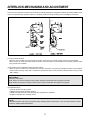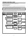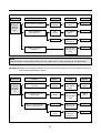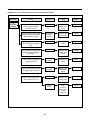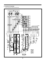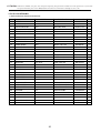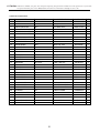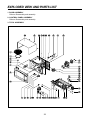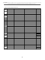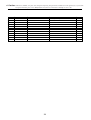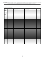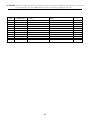
1
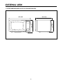
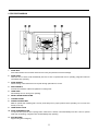
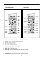
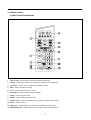
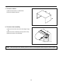
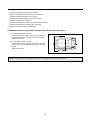
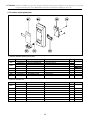
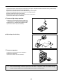
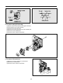
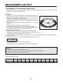
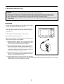
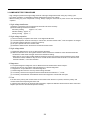
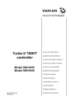
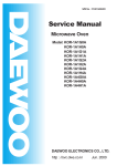
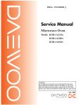
S/M No. : R631G0A003
Service Manual
Microwave Oven
Model: KOR-631G0A
KOR-631H0A
KOR-631G9A
KOR-631H9A
KOR-861G0A
KOR-861H0A
• Caution:
In this Manual, some parts can be changed for improving,
their performance without notice in the parts list. So, if you
need the latest parts information, please refer to PPL(Parts
Price List) in Service Information Center (http://svc.dwe.co.kr).
Aug. 2003
PRECAUTIONS TO BE OBSERVED BEFORE AND
DURING SERVICING TO AVOID POSSIBLE
EXPOSURE TO EXCESSIVE MICROWAVE ENERGY
(a) Do not operate or allow the oven to be operated with the door open.
(b) Make the following safety checks on all ovens to be serviced before activating the magnetron or other microwave source, and make repairs as necessary: (1) Interlock operation, (2) Proper door closing, (3) Seal and
sealing surfaces (arcing, wear, and other damage), (4) Damage to or loosening of hinges and latches, (5)
Evidence of dropping or abuse.
(c) Before turning on power to the microwave oven for any service test or inspection within the microwave generating compartments, check the magnetron, wave guide or transmission line, and cavity for proper alignment, integrity, and connections.
(d) Any defective or misadjusted components in the interlock, monitor, door seal, and microwave generation
and transmission systems shall be repaired, replaced, or adjusted by procedures described in this manual
before the oven is released to the owner.
(e) A microwave leakage check to verify compliance with the Federal performance standard should be performed on each oven prior to release to the owner.
TABLE OF CONTENTS
SAFETY AND PRECAUTIONS ...........................................................................................................................................2
FOR SAFE OPERATION ......................................................................................................................................2
FOR SAFE SERVICE PROCEDURES .................................................................................................................2
SPECIFICATIONS ...............................................................................................................................................................3
EXTERNAL VIEW................................................................................................................................................................4
OUTER DIMENSION.............................................................................................................................................4
FEATURE DIAGRAM ............................................................................................................................................5
CONTROL PANEL ................................................................................................................................................6
INSTALLATION ...................................................................................................................................................................8
OPERATIONS AND FUNCTIONS.......................................................................................................................................9
DISASSEMBLY AND ASSEMBLY....................................................................................................................................10
INTERLOCK MECHANISM AND ADJUSTMENT.............................................................................................................17
TROUBLE SHOOTING GUIDE .........................................................................................................................................18
MEASUREMENT AND TEST ............................................................................................................................................22
MEASUREMENT OF THE MICROWAVE POWER OUTPUT ............................................................................22
MICROWAVE RADIATION TEST .......................................................................................................................23
COMPONENT TEST PROCEDURE ...................................................................................................................24
WIRING DIAGRAM............................................................................................................................................................25
PRINTED CIRCUIT BOARD..............................................................................................................................................26
CIRCUIT CHECK PROCEDURE ........................................................................................................................26
PCB CIRCUIT DIAGRAM....................................................................................................................................29
P.C.B. LOCATION NO ........................................................................................................................................30
EXPLODED VIEW AND PARTS LIST...............................................................................................................................32
DOOR ASSEMBLY .............................................................................................................................................32
CONTROL PANEL ASSEMBLY..........................................................................................................................32
TOTAL ASSEMBLY.............................................................................................................................................32
1
SAFETY AND PRECAUTIONS
CAUTION
This device is to be Serviced only by Properly Qualified Service Personel. Consult the Service Manual for Proper
Service Procedures to Assure Continued Safety Operation and for Precautions to be Taken to Avoid Possible
Exposure to Excessive Microwave Energy.
1. FOR SAFE OPERATION
Damage that allows the microwave energy (that cooks or heats the food) to escape will result in poor cooking and may
cause serious bodily injury to the operator.
IF ANY OF THE FOLLOWING CONDITIONS EXIST, OPERATOR MUST NOT USE THE APPLIANCE.
(Only a trained service personnel should make repairs.)
(1) A broken door hinge.
(2) A broken door viewing screen.
(3) A broken front panel, oven cavity.
(4) A loosened door lock.
(5) A broken door lock.
The door gasket plate and oven cavity surface should be kept clean.
No grease, soil or spatter should be allowed to build up on these surfaces or inside the oven.
DO NOT ATTEMPT TO OPERATE THIS APPLIANCE WITH THE DOOR OPEN.
The microwave oven has concealed switches to make sure the power is turned off when the door is opened.
Do not attempt to defeat them.
DO NOT ATTEMPT TO SERVICE THIS APPLIANCE UNTIL YOU HAVE READ THIS SERVICE MANUAL.
2. FOR SAFE SERVICE PROCEDURES
1. If the oven is operative prior to servicing, a microwave emission check should be performed prior to servicing the
oven.
2. If any certified oven unit is found to have excessive emission level 5mw/cm2, the service person should:
(a) inform the manufacturer, importer or assembler,
(b) repair the unit at no cost to the owner,
(c) attempt to ascertain the cause of the excessive leakage,
(d) tell the owner of the unit not to use the unit until the oven has been brought into compliance.
3. If the oven operates with the door open, the service person should tell the user not to operate the oven and contact
the manufacturer and CDRH immediately.
CAUTION
MICROWAVE RADIATION
PERSONNEL SHOULD NOT BE EXPOSED TO THE MICROWAVE ENERGY WHICH MAY RADIATE FROM
THE MAGNETRON OR OTHER MICROWAVE GENERATING DEVICE IF IT IS IMPROPERLY USED OR
CONNECTED. ALL INPUT AND OUTPUT MICROWAVE CONNECTIONS. WAVEGUIDE FLANGES AND
PASKETS MUST BE SECURE. NEVER OPERATE THE DEVICE WITHOUT A MICROWAVE ENERGY
ABSORBING LOAD ATTACHED. NEVER LOOK INTO AN OPEN SAVEGUIDE OR ANTENNA WHILE THE
DEVICE IS ENERGIZED.
2
SPECIFICATIONS
MODEL
KOR-631G/H
POWER SUPPLY
POWER
CONSUMPTION
KOR-631G/H9A
KOR-861G/H
120V~60Hz, SINGLE PHASE WITH GROUNDING
MICROWAVE
1200W
1000W
1000W
800W
700W
900W
GRILL
COMBINATION
MICROWAVE ENERGY OUTPUT
MICROWAVE FREQUENCY
2450MHz
OUTSIDE DIMENSIONS (W X H X D)
465x279x360 mm (18.3x11.0x14.2 in)
495x294x388 mm (19.5x11.6x15.3 in)
CAVITY DIMENSIONS (W X H X D)
290x211x306 mm (11.4x8.3x12.0 in)
320x228x388 mm (12.6x9.0 x 13.3 in)
NET WEIGHT
Approx. 13 kg (28.66 Ibs.)
TIMER
59 min. 99 sec.
FUNCTION SELECTIONS
MICROWAVE
POWER SELECTIONS
CAVITY VOLUME
Approx. 14 kg (30.9 Ibs.)
10 LEVELS
0.7 Cu. Ft.
* SPECIFICATIONS ARE SUBJECT TO CHANGE WITHOUT NOTICE.
3
0.9 Cu. Ft.
EXTERNAL VIEW
1. OUTER DIMENSION(KOR-631G/H, 631G/H9/KOR-861G/H)
465/495
4
279/ 294
279/294
360/ 388
2. FEATURE DIAGRAM
1. DOOR SEAL
Door seal maintains the microwave within the oven cavity and prevents microwave leakage.
2. DOOR HOOK
When the door is closed, it will automatically lock shut. If door is opened while oven is operating, magnetron tube will
immediately stop operating.
3. DOOR SCREEN
Allows viewing of food. Microwave cannot pass through perforations in screen.
4. SPATTRSHIELD
Protects the microwave outlet from splashes of cooking foods.
5. OVEN LAMP
Automatically turns on during oven operating.
6. SAFETY INTERLOCK SYSTEM
7. CONTROL PANEL
8. GLASS COOKING TRAY
Made of special heat resistant glass. The tray must always be in proper position before operating. Do not cook food
directly on the tray.
9. OVEN FRONT PLATE
10. DOOR OPENING BUTTON
To open the door push the door opening button. When door is closed, it will automatically lock shut. If door is opened
while oven is operating, magnetron tube will immediately stop operating.
11. ROLLER GUIDE
Supports the glass cooling tray.
5
3. CONTROL PANEL
2) KOR-861G0A
1) KOR-631G0A/631G9A
1. Time set pad – Used to set the cooking time and the present time.
2. Display – Cooking time, power level, indicators and present time are displayed.
3. One touch – Used to cook or reheat specific quantities of food.
4. Auto cook – Used to cook or reheat.
5. More – Used to add time to cooking.
6. Less – Used to remove time from cooking.
7. Auto Defrost – Used to defrost foods. (for weight)
8. Power – Used to set power level.
9. Defrost – Used to defrost foods. (for time)
10. Kitchen Timer – Used as minute timer, delay cooking, hold setting after cooking.
11. Clock – Used to set clock.
12. Stop/Clear – Used to stop the oven operation or to delete the cooking data.
13. Start/Speedy cook – Used to start the oven and also used to set a reheat time.
6
3. CONTROL PANEL
1) KOR-631H0A/631H9A/861H0A
1. Time set pad – Used to set the cooking time and the present time.
2. Display – Cooking time, power level, indicators and present time are displayed.
3. One touch – Used to cook or reheat specific quantities of food.
4. More – Used to add time to cooking.
5. Less – Used to remove time from cooking.
6. Auto Defrost – Used to defrost foods. (for weight)
7. Power – Used to set power level.
8. Defrost – Used to defrost foods. (for time)
9. Kitchen Timer – Used as minute timer, delay cooking, hold setting after cooking.
10. Clock – Used to set clock.
11. Stop/Clear – Used to stop the oven operation or to delete the cooking data.
12. Start/Speedy cook – Used to start the oven and also used to set a reheat time.
7
INSTALLATION
1. Steady, flat location.
This microwave oven should be set on a steady, flat surface.
2. Leave space behind and side.
All air vents should be kept a clearance. If all vents are covered during operation, the oven may be overheated
and, eventually, cause oven failure.
3. Away from radio, and TV sets
Poor television reception and radio interference may result if the oven is located close to a TV, radio, antenna, or
feeder and so on.
4. Away from heating appliances and water taps
Keep the oven away from hot air, steam or splash when choosing a place to position it, or the insulation might be
adversely affected and breakdowns occur.
5. Power supply
• Check your local power source.
This microwave oven requires a current of approximately 12/10(KOR-630A9A) amperes, 120Volts, 60Hz
grounded outlet.
• Power supply cord is about 0.8 meters long.
1. A short power-supply cord is provided to reduce the risks resulting from becoming entangled in or tripping over
a longer cord.
2. Longer cord sets or extension cords are available and may be used if care is exercised in their use.
3. If a long cord or extension cord is used:
1) The marked electrical rating of the cord set or extension cord should be at least as great as the electrical rating of the appliance.
2) The extension cord must be a grounding type 3-wire cord.
3) The longer cord should be arranged so that it will not drape over the counter top or tabletop where it can be
pulled on by children or tripped over unintentionally.
6. Examine the oven after unpacking for any damage such as:
A misaligned door, broken door or a dent in cavity.
If any of the above are visible, DO NOT INSTALL, and notify dealer immediately.
8
OPERATIONS AND FUNCTIONS
1. Connect the main lead to an electrical outlet.
2. After placing the food in a suitable container, open the oven door and put it on the glass tray. The glass tray must always
be in place during cooking.
3. Close the door securely.
4. When the oven door is opened, the light turns off.
5. The oven door can be opened at any time during operation by touching the door release button on the control panel.
The oven will automatically shut off. To restart the oven, close the door and then touch START.
6. Each time a button is touched, a BEEP will sound to acknowledge the touch.
7. The oven automatically cook on full power unless set to a lower power level.
8. The display will show : 0 when the oven is plugged in.
9. Time clock returns to the present time when the cooking time ends.
10. When the STOP/CLEAR pad is touched during the oven operatiion, the oven stops cooking and all information retained.
To erase all information (except the present time), touch the STOP/SLEAR pad once more. If the oven door is opened
during the oven operation, all information is retained.
11. If the START pad is touched and the oven does not operate, check the area between the door and door is closed
securely. The oven will not start cooking under the door is completely closed or the program has been reset.
Make sure the oven is properly installed and plugged into the electrical.
Wattage output chart
The power level is set by pressing the POWER pad. The chart shows the display, the power level and the percentage
of power.
Touch POWER pad
Power level(Display)
Approximate Percentage of Power
Once
P-HI
100%
Twice
P-90
90%
3 times
P-80
80%
4 times
P-70
70%
5 times
P-60
60%
6 times
P-50
50%
7 times
P-40
40%
8 times
P-30
30%
9 times
P-20
20%
10 times
P-10
10%
11 times
P-00
0%
9
DISASSEMBLY AND ASSEMBLY
Cautions to be observed when trouble shooting.
Unlike many other appliances, the microwave oven is high-voltage, high-current equipment.
It is completely safe during normal operation.
However, carelessness in servicing the oven can result in an electric shock or possible danger from a short circuit.
You are asked to observe the following precautions carefully.
1. Always remove the power plug from the outlet before servicing.
2. Use an insulated screwdriver and ware rubber gloves when servicing the high voltage side.
3. Discharge the high voltage capacitor before touching any oven components or wiring.
(1) Check the grounding.
Do not operate on a two-wire extension cord.
The microwave oven is designed to be used while earthed.
It is imperative, therefore, to make sure it is earthed
properly before beginning repair work.
(2) Warning about the electric charge in the high voltage capacitor.
For about 30 seconds after the operation stopped and electric
charge remains in the high voltage capacitor.
When replacing or checking parts, short between oven chassis and
the negative high terminal of the high voltage capacitor by using a
properly insulated screwdriver to discharge.
4. When the 15A fuse is blown out due to the operation of the monitor
switch; replace primary interlock switch, secondary interlock switch and
interlock monitor switch.
5. After repair or replacement of parts, make sure that the screws are
properly tightened, and all electrical connections are tightened.
6. Do not operate without cabinet.
CAUTION : Service personnel should remove their watches whenever working close to or replacing the magnetron.
WARNING : When servicing the appliance, need a care of touching or replacing high potential parts because of
electrical shock or exposing microwave. These parts are as follows - HV Transformer, Magnetron,
HV Capacitor, HV Diode.
10
1. To remove cabinet
1) Remove three screws on cabinet back.
2) Push the cabinet backward.
2. To remove door assembly
1) Remove two screws which secure the stopper hinge
top.
2) Remove the door assembly from top plate of cavity.
3) Reverse the above for reassembly.
NOTE : After replacing the door assembly, perform a check of correct alignment with the hinge and cavity front plate.
11
✔ Caution: In this Service Manual, some parts can be changed for improving, their performance without notice in the parts list. So, if you need the
latest parts information, please refer to PPL(Parts Price List) in Service information Center(http://svc.dwe.co.kr)
3. To remove door parts.
1) KOR-631G0A/631H0A/631H9A/631G9A
REF NO.
A01
A02
A03
A04
A05
A06
A07
A08
A09
PART CODE
3512203870
3517006180
3515304610
3515204100
3511705500
3517002800
3512300200
3513100740
3515101300
PART NAME
FRAME DOOR
BARRIER-SCREEN*0
SUPPORTER BARR-S*0
STOPPER SINGE *T AS
DOOR WELD AS
BARRIER-SCREEN *I
GASKET DOOR
HOOK
SPRING HOOK
DESCRIPTION
ABS SG-175, SG-0760B
SAN T1.5
PP
KOR-63150S
KOR-61150S
POLYESTER T0.1
PP
POM (LG¨›˙— )
PW1
Q’TY
1
1
1
1
1
1
1
1
1
REMARK
DESCRIPTION
Q’TY
REMARK
2) KOR-861G0A/861H0A
REF NO.
PART CODE
PART NAME
A01
3512204110
FRAME DOOR
ABS XR-401, H-2938
1
A02
3517003150
BARRIER-SCREEN*0
ACRYL
1
A03
3515304410
SUPPORTER BARR-S*0
PP
1
A04
3515204100
STOPPER SINGE *T AS
KOR-63150S
1
A05
3511705620
DOOR WELD AS
KOR-81250S
1
A06
3517002900
BARRIER-SCREEN *I
POLYESTER T0.1
1
A07
3512300400
GASKET DOOR
PP
1
A08
3513100700
HOOK
POM
1
A09
3515101300
SPRING HOOK
PW1
1
12
(1) Remove the gasket door from door weld as.
(2) Remove the barrier screen inner from door weld as.
(3) Remove the door frame from door weld as.
(4) Remove the stopper hinge top from door weld as.
(5) Remove the spring and the hook.
(6) Remove the supporter barrier screen outer from door frame.
(7) Remove the barrier screen outer from door frame.
(8) Reverse the above steps for reassembly.
4. Method to reduce the gap between the door seal and the oven front surface.
(1) To reduce gap located on part ‘A’
Loosen a screws on stopper hinge top, and then push
the door to contact the door seal to oven front surface.
Tighten two screws.
(2) To reduce gap located on part ‘B’
Loosen two screws on stopper hinge under, and then
push the door to contact the door seal to oven front
surface.
Tighten two screws.
NOTE : A small gap may be acceptable if the microwave leakage does not exceed 4mW/cm2.
13
✔ Caution: In this Service Manual, some parts can be changed for improving, their performance without notice in the parts list. So, if you need the
latest parts information, please refer to PPL(Parts Price List) in Service information Center(http://svc.dwe.co.kr)
5. To remove control panel parts.
1) KOR-631G0A/631H0A/631H9A/631G9A
REF NO.
B01
B02
B03
B04
B05
B06
B07
PART CODE
3518521000
3518521010
3516719500
3516719530
3514320660
7122401211
3513702710
441G430171
3516906900
PART NAME
SWITCH MEMBRANE
SWITCH MEMBRANE
CONTROL PANEL
CONTROL PANEL
PCB AS
SCREW TAPPING
LEVER DOOR OPEN
SPRING BUTTON
BUTTON DOOR OPEN
DESCRIPTION
KOR-631G0A/9A
KOR-631H0A/9A
ABS AF-345 HFA-700HT
VT-0826, AF-348
KOR-631H9A
T2S TRS 4X12 MFZN
ABS XR-401 H-2938
SWP DIA0.7
ABS AF-345 HFA-700HT
Q’TY
REMARK
1
1
1
1
KOR-631G/H9A
1
3
1
1
1
2) KOR-861G0A/861H0A
REF NO.
PART CODE
PART NAME
DESCRIPTION
Q’TY
3518521500
SWITCH MEMBRANE
KOR-861G0A
1
3518521510
SWITCH MEMBRANE
KOR-861H0A
1
B02
3516720400
CONTROL PANEL
ABS AF-345, HFA-700HT
1
B03
3514320910
PCB MAIN AS
KOR-861G0A
1
B04
7122401211
SCREW TAPPING
T2S TRS 4X12 MFZN
1
B05
3513702710
LEVER DOOR OPEN
ABS XR-401 H-2938
1
B06
441G430171
SPRING BUTTON
SWP DIA0.7
1
B07
3516906900
BUTTON DOOR OPEN
ABS XR-401 H-2938
1
B01
14
REMARK
1) Remove the screw which secure the control panel, push up two snap fits and draw forward the control panel assembly.
2) Remove the door open lever from the control panel.
3) Remove four screws which secure the PCB assembly to control panel.
4) Disconnect membrane tail from the connector of the PCB assembly.
5) Detach membrane from the control panel.
6) Remove door open button and button spring from the control panel.
7) Reverse the above steps for reassembly.
6. To remove high voltage capacitor.
1) Remove a screw which secure the grounding ring
terminal of the H.V. diode and the capacitor holder.
2) Remove the H.V. diode from the capacitor holder.
3) Reverse the above steps for reassembly.
◆ High voltage circuit wiring
7. To remove magnetron.
1) Remove a screw which secure the magnetron.
2) Remove the magnetron.
3) Reverse the above steps for reassembly.
NOTE : Never install the magnetron without the metallic gasket plate which is packed with each magnetron to prevent microwave leakage. Whenever repair work is carried out on magnetron, check the microwave leakage.
It shall not exceed 4mW/cm2 for a fully assembled oven with door normally closed.
15
8. To remove wind guide assembly.
1) Remove a screw which secure the wind guide assembly.
2) Draw forward the wind guide assembly.
3) Pull the fan from the motor shaft.
4) Remove two screws which secure the motor shaded pole.
5) Remove the motor shaded pole.
6) Reverse the above steps for reassembly.
9. To remove H.V.transformer.
1) Remove four screws holding the H.V.transformer.
2) Remove the H.V.transformer.
3) Reverse the above steps for reassembly.
16
INTERLOCK MECHANISM AND ADJUSTMENT
The door lock mechanism is a device which has been specially designed to completely eliminate microwave radiation when
the door is opened during operation, and thus to perfectly prevent the danger resulting from the leakage of microwave.
(1) Primary interlock switch
When the door is closed, the hook locks the oven door. If the door is not closed properly, the oven will not operate.
When the door is closed, the hook pushes the button of the microswitch. Then the button of the primary interlock switch
bring it under “ON” condition.
(2) Secondary interlock switch and interlock monitor switch
When the door is closed, the hook pushes the lock lever downward. The lock lever presses the button of the interlock
monitor switch to bring it under “OFF” condition and presses the button of the secondary interlock switch to bring it under
“ON” condition.
ADJUSTMENT :
Interlock monitor switch
When the door is closed, the interlock monitor switch should be opened before other switches are closed.
When the door is opened, the interlock monitor switch should be closed after other switches are opened.
(3) Adjustment steps
a) Loosen the two mounting screws.
b) Adjust interlock switch assembly position.
c) Make sure that lock lever moves smoothly after adjustment is completed.
d) Tighten completely two mounting screws.
NOTE :
Microwave emission test should be performed after adjusting interlock mechanism. If the microwave smission exceed
4mW/cm2, readjust interlock mechanism.
17
TROUBLE SHOOTING GUIDE
Following the procedure below to check if the oven is defective or not.
1. Check grounding before trouble checking.
2. Be careful of the high voltage circuit.
3. Discharge the high voltage capacitor.
4. When checking the continuity of the switches, fuse or high voltage transformer, disconnect one lead wire from these parts
and check continuity with the AC plug removed. To do otherwise may result in a false reading or damage to your meter.
NOTE : When electric parts are checked, be sure the power cord is not inserted the wall outlet.
Check wire harness, wiring and connected of the terminals and power cord before check the parts listed
below.
(TROUBLE 1) Oven does not operate at all ; any inputs can not be accepted.
CONDITION
CHECK
RESULT
Check continuity of interlock
monitor switch with door closed
Continuity
Fuse blows.
CAUSE
Malfunction of
interlock monitor switch
REMEDY
Replace
NOTE 1
No Continuity
Replace fuse
Check continuity of of primary
interlock switch contact with door
partially open until interlock monitor switch contact close
Check continuity of primary
winding of low voltage transformer
Continuity
0Ω or infinite
Approx.
150~310
(normal)
Normal
Disconnect one side of the lead
wire connected form high voltage transformer to the high voltage capacitor and operate the
unit
Fuse again
blows
18
Shorted contacts of primary
interlock switch.
Defective low
voltage transformer
Defective high
voltage capacitor
Defective high
voltage transformer
Replace
NOTE 1
Replace
Replace
Replace
CONDITION
Outlet has
proper voltage Fuse
does not
blow.
CHECK
RESULT
CAUSE
REMEDY
No
Continuity
Defective magnetron
Replace
Check continuity of magnetron
Check continuity of
power supply cord
No
Continuity
Open power supply cord
Replace
Normal
Defective touch
control circuit
Replace
Malfunction of secondary interlock
switch
Replace
Display do not shown
countdown
NOTE
All these switches must be replaced at the same time, please refer to “Interlock Mechanism And Adjustment”.
(TROUBLE 2) Display shows all figures selected, but oven does not start cooking, even though desired program and
time are set and start button is tapped.
CONDITION
CHECK
RESULT
CAUSE
REMEDY
Turn table
motor and
oven lamp
do not turn
on
Check continuity of primary interlock switch
No
Continuity
Malfunction of primary interlock
switch
Adjust or
replace
Check continuity of secondary
interlock switch
No
Continuity
Check D.C. voltage being supplied to RELAY (RY2) coil
0V
Defective touch
control circuit
Approx.
15 VDC
Faulty contacts of
RELAY (RY2) or
open relay coil
19
Malfunction of secondary interlock
switch
Adjust or
replace
Replace
Replace
(TROUBLE 3)
CONDITION
No
microwave
oscillation
No microwave oscillation even though fan motor rotates.
CHECK
RESULT
CAUSE
REMEDY
Check continuity of high
voltage capacitor terminals
with wires removed
Continuity
Defective high
voltage transformer
Replace
Check continuity of high voltage
rectifier in forward and backward
direction with DC megger
Continuity in
backward
direction
Defective high
voltage rectifier
Replace
Connect megger leads to magnetron terminal and magnetron
body
Continuity
Defective magnetron
Replace
Defective high
voltage transformer
Replace
0 Ω or ∞
Check resistance of primary and
secondary coil of high voltage
transformer
No
Continuity
Check continuity of magnetron
with wires removed
No
Continuity
Check continuity of filament terminal of high voltage transformer
Defective magnetron
Defective high
voltage transformer
0V
Check D.C. voltage being supplied to RELAY (RY1) coil
Defective touch
control circuit
Approx
15 VDC
20
Faulty
contacts or
RELAY (RY1)
or open
relay coil
Replace
Replace
Replace
Replace
(TROUBLE 4)
The following visual conditions indicate a probable defective touch control circuit or membrane switch
assembly.
1. Incomplete segments
(1) Segments missing
(2) Partical segments missing
(3) Digit flickering other than normal display slight flickering
(4) “ :0” does not display when power is on.
2. A distinct change in the display is not on when it should be.
3. One or more digits in the display are not on when they should be.
4. Display indicates a number different from one touched.
5. Specific numbers (for example 2 or 3) will not display when the knob is turned.
6. Display does not count down or up with time cooking or clock operation.
7. Oven is programable and cooks normally but no display shows.
8. Display obviously jumps in time while counting down.
9. Display counts down noticeably too fast while cooking.
10. Display does not show the time of day when cancel button is touched.
11. Oven lamp and turntable motor do not stop although cooking is finished. Check if the RELAY 2 contacts close if they are
close, replace touch control circuit.
CONDITION
CHECK
Display does
not show
programming
at all, even if
keyboard is
touched.
Check rach pad for
continuity of the membrane
keyboard for the following keyboard check procedure
RESULT
Normal
Abnormal
CAUSE
REMEDY
Malfunction
of touch
control circuit
of control box
sub-assembly
Replace control box subassembly
Malfunction
of the membrane
keyboard
Replace the
membrane
keyboard
NOTE
Before following the particular steps listed above in the trouble shooting guide for the membrane keyboard's,
failure, please check for the continuity of each wire-harness between the membrane keyboard and P.C.B.
assembly.
21
MEASUREMENT AND TEST
1. MEASUREMENT OF THE MICROWAVE POWER OUTPUT
Microwave output power can be checked by indirectly measuring the temperature rise of a certain amount of water
exposed to the microwave as directed below.
PROCEDURE
1. Microwave power output measurement is made with the microwave oven
supplied at rated voltage and operated at its maximum microwave power
setting with a load of 1000±5cc of potable water.
2. The water is contained in a cylindrical borosilicate glass vessel having a
maximum material thickness of 3 mm and an outside diameter of approximately 190 mm.
3. The oven and the empty vessel are at ambient temperature prior to the start
of the test.
The initial temperature of the water is 10±2˚C (50±3.6˚F)
It is measured immediately before the water is added to the vessel.
After addition of the water to the vessel, the load is immediately placed on
the center of the shelf, which is in the lowest normal position.
4. Microwave power is switched on.
5. Heating time should be exactly A seconds. (Refer to table as following)
Heating time is measured while the microwave generator is operating at full power.
The filament heat-up time for magnetron is not included.
6. The initial and final temperature of water is selected so that the maximum difference between the ambient and final water
temperature is 5K.
7. The microwave power output P in watts is calculated from the following formula :
P=4187 X ▲T/t
• ▲T is difference between initial and ending temperature.
• It is the heating time.
The power measured should be B (Refer to SPECIFICATIONS)W±10.0%.
CAUTION :
1. Water load should be measured exactly to 1 liters.
2. Input power voltage should be exactly specified voltage(Refer to SPECIFICATIONS).
3. Ambient temperature should be 20±2˚C(68±3.6˚F)
• Heating time for power output:
A(second)
70
64
60
56
52
49
47
44
42
40
38
B(W)
600
650
700
750
800
850
900
950
1000
1050
1100
22
2. MICROWAVE RADIATION TEST
CAUTION :
1. Make sure to check the microwave leakage before and after repair of adjustment.
2. Always start measuring of an unknown field to assure safety for operating personnel from microwave energy.
3. Do not place your hands into any suspected microwave radiation field unless the safe density level is known.
4. Care should be taken not to place the eyes in direct line with the source of microwave energy.
5. Slowly approach the unit under test until the radiometer reads an appreciable microwave leakage from the unit
under the test.
PROCEDURES
1. Prepare Microwave Energy Survey Meter, 600cc glass
beaker, and glass thermometer 100˚C(212˚F).
2. Pour 275cc±15cc of tap water initially at 20±5˚C(68±9˚F) in
the 600cc glass beaker with an inside diameter of approx.
95mm(3.5in.).
3. Place it at the center of the tray and set it in a cavity.
4. Close the door and operate the oven.
5. Measure the leakage by using Microwave Energy Survey
Meter with dual ranges, set to 2450MHz.
1) Measured radiation leakage must not exceed the value
prescribed below. Leakage for a fully assembled oven with
door normally closed must be less than 4mW/cm2.
2) When measuring the leakage, always use the 5cm(2in.)
space cone with probe. Hold the probe perpendicular to
the cabinet and door. Place the space cone of the probe
on the door, cabinet, door seem, door viewing screen, the
exhaust air vents and the suction air vents.
3) Measuring should be in a counter-clockwise direction at a
rate of 1 in./sec. If the leakage of the cabinet door seem is
unknown, move the probe more slowly.
4) When measuring near a corner of the door, keep the probe
perpendicular to the areas making sure the probe end at the base of the cone does not get closer than 2 in. from any
metal. If it does not, erroneous reading may result.
23
3. COMPONENT TEST PROCEDURE
• High voltage is present at the high voltage terminal of the high voltage transformer during any cooking cycle.
• It is neither necessary nor advisable to attempt measurement of the high voltage.
• Before touching any oven components or wiring, always unplug the oven from its power source and discharge the
capacitor.
1. High voltage transformer
(1) Remove connections from the transformer terminals and check continuity.
(2) Normal readings should be as follows:
Secondary winding
Approx. 110Ω±10%
Filament winding Approx. 0Ω
Primary winding Approx. 1Ω
2. High voltage capacitor
(1) Check continuity of capacitor with meter on the highest OHM scale.
(2) A normal capacitor will show continuity for a short time, and then indicate 10MΩ once the capacitor is charged.
(3) A shorted capacitor will show continuous continuity.
(4) An open capacitor will show constant 10MΩ.
(5) Resistance between each terminal and chassis should be infinite.
3. High voltage diode
(1) Isolate the diode from the circuit by disconnecting the leads.
(2) With the ohmmeter set on the highest resistance scale measure the resistance across the diode terminals.
Reverse the meter leads and again observe the resistance reading.
Meter with 6V, 9V or higher voltage batteries should be used to check the front-back resistance of the diode,
otherwise an infinite resistance may be read A normal diode’s resistance will be infinite in one direction and
several hundred KΩ in the other direction.
4. Magnetron
For complete magnetron diagnosis, refer to “Measurement of the Microwave Power Output”.
Continuity checks can only indicate and open filament or a shorted magnetron.
To diagnose for an open filament or a shorted magnetron.
(1) Isolate magnetron from the circuit by disconnecting the leads.
(2) A continuity check across magnetron filament terminals should indicate 0.1Ω or less.
(3) A continuity check between each filament terminal and magnetron case should read open.
5. Fuse
If the fuse in the primary and monitor switch circuit is blown when the door is opened, check the primary and
monitor switch before replacing the blown fuse.
In case the fuse is blown by an improper switch operation, replace the defective switch and fuse at the same time.
Replace just the fuse if the switches operate normally.
24
WIRING DIAGRAM
25
PRINTED CIRCUIT BOARD
1. CIRCUIT CHECK PROCEDURE
1. Low Voltage Transformer check
• The low voltage transformer is located on the P.C.B.
• Measuring condition: input voltage : 120V/Frequency : 60Hz
Terminal Voltage
4-7
LOAD
AC 12.6 V
NO LOAD
AC 14.7 V
NOTE :
1. Refer to Circuit Diagram (point 4).
2. Secondary side voltage of the low voltage transformer changes in proportion to fluctuation of power source voltage.
3. The allowable tolerance of the secondary voltage is within ± 5% of nominal voltage.
2. Voltage check
• Key check point
NO
CHECK POINT
REMARK
1
IC 1 PIN 2, 21, 30, 34
-5 VDC
2
IC 1 PIN 35
T:16.7ms(60Hz)
3
IC 1 PIN 31 OR 32
T:250ns(4MHz)
• Check method
NO
MEASURE POINT
1
MP1
2
MP2
WAVE FORM
REMEDY
REMARK
DC -5V±0.25V
Replace VL1, EC1
NO LOAD
DC -12V±2.0V
Replace EC2, D12, 13, 14
NO LOAD
NOTE :
Each measure point must be measured with GND points.
26
Measure Point
27
3. When there is no microwave oscillation
1) When touching START pad, oven lamp does not turn on.
Fan motor do not rotate, but cook indicator in display comes on.
* Cause : RELAY 2 does not operate. → refer to Circuit Diagram (Point 3)
- Check method
POINT
A
B
RELAY 2 ON
-5VDC
GND
RELAY 2 OFF
GND
-12VDC
STATE
2) When touching START pad, oven lamp turns on.
Fan motor and turntable rotate and cook indicator in display comes on.
* Cause : RELAY 1 does not operate. → refer to Circuit Diagram (Point 2)
- Check method
POINT
A
B
RELAY 1 ON
-5VDC
GND
RELAY 1 OFF
GND
-12VDC
STATE
4. When the door is opened during operation, the count down timer does not stop.
→ refer to Circuit Diagram (Point 1)
-Check method
POINT
A
B
1) DOOR OPEN
OPEN
-5VDC
2) DOOR CLOSED
CLOSE
GND
STATE
CHECK NO
1
METHOD
REMEDY
Check the stage (ON, OFF) of the door open monitor switch by
resistance measurement.
5. When the digital clock does not operate properly.
→ refer to Circuit Diagram (Point 5)
POINT
WAVE FORM
A
T:16.7ms(60Hz)
* If clock does not keep exact time, you must check resistor R15, 16 zener diode ZD1.
28
Replace door open monitor
switch.
2. PCB CIRCUIT DIAGRAM
1) KOR-631G0A/631H0A/631H9A/631G9A
29
✔ Caution: In this Service Manual, some parts can be changed for improving, their performance without notice in the parts list. So, if you need the
latest parts information, please refer to PPL(Parts Price List) in Service information Center(http://svc.dwe.co.kr)
3. P.C.B. LOCATION NO.
1) KOR-631G0A/631H0A/631H9A/631G9A
NO.
NAME
SYMBOL
SPECIFICATION
PART CODE
Q'TY
1
BUZZER
BZ1
BM-20K
3515600100
1
2
C ARRAY
CA1
7P(6) 102 M 50V
CN6XB-102M
1
3
CAPACITOR ELEC
EC1
25V RSS 100uF
CEXE1C101V
1
4
CAPACITOR ELEC
EC2
25V RSS 1000uF
DEZF1E102V
1
5
CONNECTOR WAFER
CN1
YW396-02AV
3519150520
1
6
CONNECTOR WAFER
CN2
YW396-05AV
3519150510
1
7
CONNECTOR WAFER
CN3
FCZ254-11
441M367160
1
8
DIODE RECTIFY
D1~6, 9~12
1N4148
DZN4148---
10
9
DIODE RECTIFY
D13, 14
1N4002A
DZN4002A--
2
10
DIODE ZENER
ZD1
MTZ 5.1VB 1/2W
DZTZ5R1B--
2
11
DIODE ZENER
ZD2
MTZ 3.9VB 1/2W
DZTZ3R9B--
1
12
LED DISPLAY
DP1
DDG-631H
DDDG631H--
1
13
PCB MAIN
M158
81.5X139.9
3514315410
1
14
R ARRAY
RA1
7P(6) 1/8 100K J
RD-87X104J
1
15
RESISTOR
R1~R7
1/6W 330 5%
RD-AZ331J-
7
16
RESISTOR
R8,10,12,14,22
1/6W 1K 5%
RD-AZ102J-
5
17
RESISTOR
R11,20,21
1/6W 100K 5%
RD-AZ104J-
3
18
RESISTOR
R13
1/6W 100 5%
RD-AZ101J-
1
19
RESISTOR
R15~17
1/6W 10K 5%
RD-AZ103J-
3
20
RESISTOR
R18
1/6W 1M 5%
RD-AZ105J-
1
21
RESISTOR
R19
1/4W 51 5%
RD-4Z510J-
1
22
REGULATOR
VL1
MC7905C
1MC7905C--
1
23
TRANSISTOR
Q1~5, 9~11
KRA-102M
TZRA102M--
8
24
TRANSISTOR
Q6
KTA-1270Y
TZTA1270Y-
1
25
TRANS POWER
LVT1
DMR-631P
5EPU035302
1
26
WIRE COPPER
J1-J21
1/0.52 TIN COATING
85801052GY
21
27
WIRE COPPER
SJ3
1/0.52 TIN COATING
85801052GY
1
28
IC MICOM
IC1
TMP47C440BN
13GS862GH0
1
29
RESONATOR CERA
CR1
KBR-4.0MSTF
5PKBR40MKS
1
30
SW RELAY
RY1
G5G-1A DC12V
5SC0101121
1
31
SW RELAY
RY2
O5B-1 DC12V
5SC0101110
1
32
CAPACITOR CERA
C6
102 50V Z AXIAL
CCZB1H102K
1
33
CAPACITOR CERA
C1~5,C7
104 50V Z AXIAL
CCZF1H104Z
6
30
✔ Caution: In this Service Manual, some parts can be changed for improving, their performance without notice in the parts list. So, if you need the
latest parts information, please refer to PPL(Parts Price List) in Service information Center(http://svc.dwe.co.kr)
2) KOR-861G0A/861H0A
NO.
NAME
SYMBOL
SPECIFICATION
PART CODE
Q'TY
1
BUZZER
BZ1
BM-20K
3515600100
1
2
C ARRAY
CA1
7P(6) 102 M 50V
CN6XB-102M
1
3
CAPACITOR ELEC
EC1
16V RSS 100uF
CEXF1C101V
1
4
CAPACITOR ELEC
EC2
25V RSS 1000uF
CEXF1C102V
1
5
CONNECTOR WAFER
CN1
YW396-02V
3519150520
1
6
CONNECTOR WAFER
CN2
YW396-05V
3519150510
1
7
CONNECTOR WAFER
CN3
FCZ254-11
441M367160
1
8
DIODE RECTIFY
D1~6, 9~12
1N4148
DZN4148---
10
9
DIODE RECTIFY
D13, 14
1N4002A
DZN4002A--
2
10
DIODE ZENER
ZD1
MTZ 5.1B 1/2W
DZTZ5R1B--
2
11
DIODE ZENER
ZD2
MTZ 3.9B 1/2W
DZTZ3R9B--
1
12
LED DISPLAY
DP1
DDG-631H
DDDG631H--
1
13
PCB MAIN
M158
81.5X139.9
3514315410
1
14
R ARRAY
RA1
7P(6) 1/8 100K J
RA-87X104J
1
15
RESISTOR
R1~R7
1/6W 330 5%
RD-AZ331J-
7
16
RESISTOR
R8,9,10,14,22
1/6W 1K 5%
RD-AZ102J-
5
17
RESISTOR
R11,20,21
1/6W 100K 5%
RD-AZ104J-
3
18
RESISTOR
R13
1/6W 100K 5%
RD-AZ101J-
1
19
RESISTOR
R15~17
1/6W 10K 5%
RD-AZ103J-
3
20
RESISTOR
R18
1/6W 1M 5%
RD-AZ105J-
1
21
RESISTOR
R19
1/4W 51 5%
RD-AZ510J-
1
22
REGULATOR
VL1
MC7905C
1MC7905C--
1
23
TRANSISTOR
Q1~5, 9~11
KRA-102M
TZRA102M--
8
24
TRANSISTOR
Q6
KTA-1270Y
TZTA1270Y-
1
25
TRANS POWER
LVT1
DMR-631P
5EPU035302
1
26
WIRE COPPER
J1-J21
1/0.52 TIN COATING
85801052GY
21
27
WIRE COPPER
SJ1,SJ3
1/0.52 TIN COATING
85801052GY
2
28
IC MICOM
IC1
TMP47C440BN
13GS862GH0
1
29
RESONATOR CERA
CR1
KBR-4.0MSTF
5PKBR40MKS
1
30
SW RELAY
RY1
G5G-1A DC12V
5SC0101121
1
31
SW RELAY
RY2
G5B-1DC12V
5SC0101110
1
32
CAPACITOR CERA
C6
102 50V Z AXIAL
CCZB1H102K
1
33
CAPACITOR CERA
C1~5,C7
104 50V Z AXIAL
CCZF1H104Z
6
31
EXPLODED VIEW AND PARTS LIST
1. DOOR ASSEMBLY
Refer to Disassembly and assembly.
2. CONTROL PANEL ASSEMBLY
Refer to Disassembly and assembly.
3. TOTAL ASSEMBLY
32
✔ Caution: In this Service Manual, some parts can be changed for improving, their performance without notice in the parts list. So, if you need the
latest parts information, please refer to PPL(Parts Price List) in Service information Center(http://svc.dwe.co.kr)
1) KOR-631G0A/631H0A/631H9A/631G9A
NO
A00
B00
F01
F02
F03
F04
F05
F06
F07
F08
F09
F10
F11
F12
F13
F14
F15
F16
F17
F18
F19
F20
F21
F22
F23
F24
F25
F26
F27
F28
F29
F30
F31
F32
F33
PART CODE
3511710300
3511714400
3516721410
3516721420
3516721230
3510801310
3516004100
3516109000
3516109600
7112401011
7122401211
7122401211
7112401011
35113NAN0H
4413A90012
7122401211
7121403011
3963821600
3963821620
3512517000
3511800300
3518002200
3516004000
7272400811
3513003200
3518301600
3518301501
3518400400
3518114400
3518114450
3516003700
3510311700
7112401011
3512100900
7S422X4081
3515201101
4415A17352
4415A17352
4415A66600
4415A17352
3518571000
3513702600
PART NAME
DOOR AS
DOOR AS
CONTROL-PANEL AS
CONTROL-PANEL AS
CONTROL-PANEL AS
CABINET
SPECIAL SCREW
CAVITY WELD AS
CAVITY JOINT AS
SCREW TAPPING
SCREW TAPPING
SCREW TAPPING
SCREW TAPPING
CORD POWER AS
CLAMP POWER CORD
SCREW TAPPING
SCREW TAPPING
MOTOR SHADED POLE
MOTOR SHADED POLE
GUIDE WIND
FAN
MAGNETRON
SPECIAL SCREW
SCREW SPECIAL
HOLDER HV CAPACITOR
CAPACITOR HV
CAPACITOR HV
DIODE HV
TRANS HV
TRANS HV
SPECIAL SCREW
BASE
SCREW TAPPING
FOOT
SCREW TAPTITE
STOPPER HINGE *U
FUSE
HOLDER FUSE
SW MICRO
SW MICRO
SW MICRO
SW MICRO
LEVER LOCK
33
DESCRIPTION
KOR-63150S
KOR-631H9A
KOR-631G0A
KOR-631H0A
KOR-631H9A
PCM T0.36 GE
T1 TRS LR4 POLE 4*10 MFZN
CAVITY WELD AS
CAVITY WELD AS
T1 TRS 4*10 MFZN
T2S TRS 4*12 MFZN
T2S TRS 4*12 MFZN
T1 TRS 4*10 MFZN
3X18AWG 60X60 120-RTML
NYLON66
T2S TRS 4*12 MFZN
T2S PAN 4X30 MFZN
120V 21W OEM-10DWX1-A07
120V 21W MW08XA-A01
PP
PP+30%GLASS
2M218H(MF) I
T2 BOLT FLANGE 5X12 DACRO
TT3 TRS 4X8 SE MFZN
SECC T0.6
2100VAC 0.79µF #187
2100VAC 0.77µF #187
HVR-1X-3AB 12KV #187
JMOT-N80A0-63T
DT-N70A0-63T
TT3 HEX 4X8 FLG MFZN
SBHG T0.8
T1 TRS 4*10 MFZN
PP DASF-130
TT3 TRS 4X8 MFZN
SCP-1
120/250V 15A
NYLON66
VP-533A-OF SPNO #187 200G
VP-532A-OF/SZM-V16-FA-62
VP-533A-OF SPNO #187 200G
MP101C
POM
Q'TY
1
1
1
1
1
1
3
1
1
1
1
1
1
1
1
1
2
1
KOR-631G/H9A
1
1
1
1
1
1
1
KOR-631G/H9A
1
KOR-631G/H9A
1
4
1
5
2
1
1
1
1
1
1
1
KOR-631G/H9A
1
✔ Caution: In this Service Manual, some parts can be changed for improving, their performance without notice in the parts list. So, if you need the
latest parts information, please refer to PPL(Parts Price List) in Service information Center(http://svc.dwe.co.kr)
NO
F35
F36
F37
F38
F39
F40
F41
F42
F43
F44
F45
F46
PART CODE
3513811720
3513601500
7121400611
3966820200
3518905300
3513003400
3516003700
3511406200
3517400620
3514700710
3512517300
3517203600
PART NAME
LOCK
LAMP
SCREW TAPPING
MOTOR SYNCRO
THERMOSTAT
HOLDER THERMOSTAT
SPECIAL SCREW
COVER WAVE GUIDE
COUPLER
ROLLER
GUIDE ROLLER
TRAY
34
DESCRIPTION
POM (LG¨›˙— )
BL 125V 25W T25 C5A H187
T2S PAN 4X6 MFZN
120V 2W GM-16-12F17
OFF:75 ON:65 H #187 NB
PBT
TT3 HEX 4X8 FLG MFZN
HEATPROOF PP
XAREC
TEFLON
PP
GLASS
Q'TY1
1
1
1
1
1
1
1
1
1
3
1
1
✔ Caution: In this Service Manual, some parts can be changed for improving, their performance without notice in the parts list. So, if you need the
latest parts information, please refer to PPL(Parts Price List) in Service information Center(http://svc.dwe.co.kr)
1) KOR-861G0A/861H0A
NO
A00
B00
F01
F02
F03
F04
F05
F06
F07
F08
F09
F10
F11
F12
F13
F14
F15
F16
F17
F18
F19
F20
F21
F22
F23
F24
F25
F26
F27
F28
F29
F30
F31
F32
F33
PART CODE
3511710700
3516721110
3516721120
3510801400
3516004100
3516109200
3516109700
7112401011
7122401211
7122401211
7112401011
35113TANT5
4413A90012
7122401211
7121403011
3518601600
3512517000
3511800300
3518002200
3516004000
7S422X4081
3513003200
3518301800
3516004000
3518114700
3516003700
3510311900
7112401011
3512100900
7S422X4081
3515201101
4415A17352
4415A66600
4415A66600
4415A17352
3513702600
PART NAME
DOOR AS
CONTROL-PANEL AS
CONTROL-PANEL AS
CABINET
SPECIAL SCREW
CAVITY WELD AS
CAVITY JOINT AS
SCREW TAPPING
SCREW TAPPING
SCREW TAPPING
SCREW TAPPING
CORD POWER AS
CLAMP POWER CORD
SCREW TAPPING
SCREW TAPPING
MOTOR SHADED POLE
GUIDE WIND
FAN
MAGNETRON
SPECIAL SCREW
SCREW SPECIAL
HOLDER HV CAPACITOR
CAPACITOR HV
DIODE HV
TRANS HV
SPECIAL SCREW
BASE
SCREW TAPPING
FOOT
SCREW SPECIAL
STOPPER HINGE *U
FUSE
HOLDER FUSE
SW MICRO
SW MICRO
SW MICRO
LEVER LOCK
35
DESCRIPTION
KOR-86150S
KOR-861G0A
KOR-861H0A
PCM T0.6
T1 TRS 4*10 SE MFZN
CAVITY WELD AS
CAVITY WELD AS
T1 TRS 4*10 MFZN
T2S TRS 4*12 MFZN
T2S TRS 4*12 MFZN
T1 TRS 4*10 MFZN
3X0.75 40X40 120-RTML
NYLON66
T2S TRS 4*12 MFZN
T2S TRS 4X30 MFZN
120V 21W OEM-10DWX1-A07
PP
PP+30% GLASS
2M218H(MF) I
T2 BOLT FLANGE 5X12 DACRO
TT2 TRS 4X8 SE MFZN
SECC T0.6
2100VAC 0.77µF #187
HVR-1X-3AB 12KV #187
JMOT-N90A0-86T
TT3 HEX 4X8 FLG MFZN
SBHG T0.8
T2 TRS 4*10 MFZN
PP DASF-130
TT3 TRS 4X48 SM MFZN
SCP-1 T2.5
120/250V 15 A
NYLON66
VP-532A-OF SPNO #187 200KG
VP-533A-OF/SZM-V16-FA-62
VP-533A-OF SPNO #187 200G
POM
Q'TY
1
1
1
1
3
1
1
1
1
1
1
1
1
1
2
1
1
1
1
1
1
1
1
1
1
4
1
5
2
1
1
1
1
1
1
1
1
✔ Caution: In this Service Manual, some parts can be changed for improving, their performance without notice in the parts list. So, if you need the
latest parts information, please refer to PPL(Parts Price List) in Service information Center(http://svc.dwe.co.kr)
NO
F35
F36
F37
F38
F39
F40
F41
F42
F43
F44
F45
F46
PART CODE
3513811700
3513601500
7121400611
3966820200
3518905300
3513003400
3516003700
3511406200
3517400620
3514700900
3512509200
3517203500
PART NAME
LOCK
LAMP
SCREW TAPPING
MOTOR SYNCRO
THERMOSTAT
HOLDER THERMOSTAT
SPECIAL SCREW
COVER WAVE GUIDE
COUPLER
ROLLER
GUIDE ROLLER
TRAY
36
DESCRIPTION
POM
BL 125V 25W T25 C5A H187
T2S PAN 4X6 MFZN
120V 2W GM-16-12F17
OFF:75 ON:65 H#187 NB
PBT
TT3 TRS 4X8 MFZN
HEATPRO OF PP
XAREC
TEFLON
PP
GLASS
Q'TY
1
1
1
1
1
1
1
1
1
3
1
1
DAEWOO ELECTRONICS CO., LTD.
686, AHYEON-DONG MAPO-GU SEOUL, KOREA
C.P.O. BOX 8003 SEOUL, KOREA
TELEX: DWELEC K28177-8
CABLE: “DAEWOOELEC”
S/M NO. : R631G0A003
PRINTED DATE: Aug. 2001