1
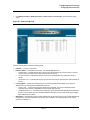
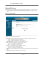
Table of Contents
D-Link DES-3010FA/GA User Guide Overview............................................................................... 7
Using the Installation Guide .......................................................................................................................7
Using the Embedded Web Interface User Guide .......................................................................................7
Intended Audience........................................................................................................................... 8
D-Link DES 3010FA/GA Installation Guide................................................................................... 9
Device Description ................................................................................................................ 10
Viewing the Device ........................................................................................................................ 11
DES-3010FA Front Panel ........................................................................................................................11
DES-3010GA Front Panel .......................................................................................................................11
Ports Description ........................................................................................................................... 13
10/100Base-TX Fast Ethernet Ports.......................................................................................................13
1000Base-T Gigabit Ethernet Ports.........................................................................................................13
100Base-FX Fiber Ports ..........................................................................................................................13
SFP Port ..................................................................................................................................................13
DB-9 Console Port...................................................................................................................................14
Cable Specifications ...................................................................................................................... 15
LED Defiitions................................................................................................................................ 16
Port LEDs ................................................................................................................................................16
Power LED...............................................................................................................................................19
Console LED............................................................................................................................................19
Cable, Port, and Pinout Information ..............................................................................................20
Pin Connections for the 10/100/1000 Ethernet Interface.........................................................................20
Physical Dimensions ..................................................................................................................... 21
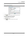
Mounting Device ................................................................................................................... 22
Preparing for Installation................................................................................................................ 23
Installation Precautions............................................................................................................................23
Site Requirements ...................................................................................................................................23
Unpacking................................................................................................................................................24
Installing the Device ...................................................................................................................... 25
Desktop or Shelf Installation ....................................................................................................................25
Rack Installation ......................................................................................................................................25
Wall Installation........................................................................................................................................28
Connecting the Device .................................................................................................................. 29
Connecting the Switch to a Terminal .......................................................................................................29
AC Power Connection .............................................................................................................................30
Starting and Configuring the Device ..................................................................................... 31
Configuring the Terminal ............................................................................................................... 32
Installation Procedure .................................................................................................................... 32
Device Port Default Settings....................................................................................................................32
Page 1
D-Link DES-3010FA/GA User Guide
Booting the Device ........................................................................................................................ 33
Configuration Overview................................................................................................................. 34
Initial Configuration ................................................................................................................................. 34
Advanced Configuration................................................................................................................ 39
Receiving an IP Address from a DHCP Server....................................................................................... 39
Receiving an IP Address from a BOOTP Server .................................................................................... 39
Security Management and Password Configuration............................................................................... 40
Startup Procedures ....................................................................................................................... 43
Startup Menu Procedures ....................................................................................................................... 43
Software Download and Reboot ............................................................................................................. 44
D-Link DES 3010FA/GA EWS User Guide................................................................................. 48
Getting Started...................................................................................................................... 49
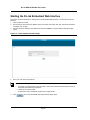
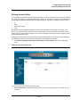
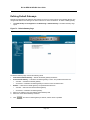
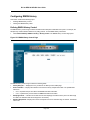
Starting the D-Link Embedded Web Interface............................................................................... 50
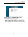
Understanding the D-Link Embedded Web Interface.................................................................... 51
Device Representation............................................................................................................................ 53
Using the D-Link Embedded Web Interface Management Buttons ........................................................ 53
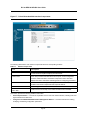
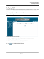
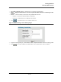
Using Screen and Table Options .................................................................................................. 54
Adding Configuration Information ........................................................................................................... 54
Modifying Configuration Information ....................................................................................................... 54
Deleting Configuration Information ......................................................................................................... 55
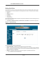
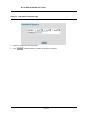
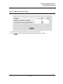
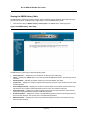
Resetting the Device ..................................................................................................................... 56
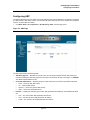
Logging off from the Device .......................................................................................................... 58
Managing Device Information ............................................................................................... 59
Configuring Device Security.................................................................................................. 61
Configuring Management Security................................................................................................ 62
Configuring Authentication Methods ....................................................................................................... 62
Configuring Passwords ........................................................................................................................... 79
Configuring Network Security........................................................................................................ 83
Network Security Overview..................................................................................................................... 83
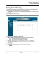
Defining Network Authentication Properties ........................................................................................... 84
Defining Port Authentication ................................................................................................................... 86
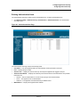
Configuring Traffic Control ...................................................................................................................... 92
Configuring Ports .................................................................................................................. 97
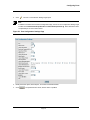
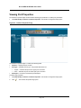
Viewing Port Properties............................................................................................................... 100
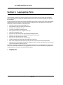
Aggregating Ports ............................................................................................................... 102
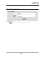
Aggregating Ports ....................................................................................................................... 103
Configuring LACP ....................................................................................................................... 105
Configuring VLANs ............................................................................................................. 107
Defining VLAN Properties ........................................................................................................... 108
Defining VLAN Membership........................................................................................................ 110
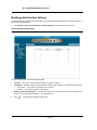
Defining VLAN Interface Settings................................................................................................ 111
Page 2
Defining Private VLANs ...............................................................................................................113
Configuring GARP .......................................................................................................................116
Defining GARP ......................................................................................................................................116
Defining GVRP ......................................................................................................................................118
Configuring IP Information .................................................................................................. 120
Configuring IP Interfaces .............................................................................................................120
Defining IP Addresses ...........................................................................................................................121
Defining Default Gateways ....................................................................................................................124
Configuring DHCP .................................................................................................................................125
Configuring ARP ....................................................................................................................................127
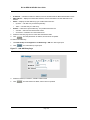
Configuring Domain Name Servers .............................................................................................129
Defining DNS Servers............................................................................................................................130
Defining DNS Host Mapping..................................................................................................................132
Defining the Forwarding Database ..................................................................................... 134
Defining Static Forwarding Database Entries ..............................................................................135
Defining Dynamic Forwarding Database Entries .........................................................................137
Configuring Spanning Tree ................................................................................................. 139
Defining Classic Spanning Tree ..................................................................................................140
Defining STP on Interfaces..........................................................................................................142
Defining Rapid Spanning Tree ....................................................................................................145
Defining Multiple Spanning Tree .................................................................................................148
Defining MSTP Instance Settings ..........................................................................................................148
Defining MSTP Interface Settings..........................................................................................................151
Configuring Multicast Forwarding ....................................................................................... 154
Defining IGMP Snooping .............................................................................................................155
Defining Multicast Bridging Groups .............................................................................................157
Defining Multicast Forward All Settings .................................................................................................159
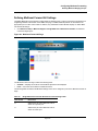
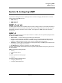
Configuring SNMP .............................................................................................................. 161
SNMP v1 and v2c........................................................................................................................161
SNMP v3 .....................................................................................................................................161
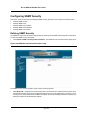
Configuring SNMP Security .........................................................................................................162
Defining SNMP Security ........................................................................................................................162
Defining SNMP Views............................................................................................................................164
Defining SNMP Group Profiles ..............................................................................................................166
Defining SNMP Group Members ...........................................................................................................169
Defining SNMP Communities ................................................................................................................172
Configuring SNMP Notifications ..................................................................................................175
Defining SNMP Notification Global Parameters ....................................................................................176
Defining SNMP Notification Filters.........................................................................................................177
Defining SNMP Notification Recipients..................................................................................................179
Page 3
D-Link DES-3010FA/GA User Guide
Configuring Quality of Service ............................................................................................ 183
VPT Classification Information .................................................................................................... 183
CoS Services .............................................................................................................................. 184
Configuring Quality of Service General Settings......................................................................... 185
Defining QoS Settings........................................................................................................................... 185
Defining Bandwidth Settings ....................................................................................................... 187
Modifying QoS Interface Settings ......................................................................................................... 188
Defining Queue Settings ....................................................................................................................... 190
Mapping QoS Queues................................................................................................................. 191
Mapping CoS Values to Queues........................................................................................................... 191
Mapping DSCP Values to Queues........................................................................................................ 192
Managing System Files....................................................................................................... 193
File Management Overview ........................................................................................................ 194
Downloading System Files.......................................................................................................... 195
Firmware Download .............................................................................................................................. 195
Configuration Download........................................................................................................................ 196
Uploading System Files .............................................................................................................. 197
Upload Type.......................................................................................................................................... 197
Software Image Upload ........................................................................................................................ 198
Configuration Upload ............................................................................................................................ 198
Copying Files ........................................................................................................................................ 199
Restoring the Default Configuration File ............................................................................................... 199
Managing System Logs ...................................................................................................... 200
Enabling System Logs ................................................................................................................ 201
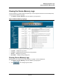
Viewing the Device Memory Logs............................................................................................... 203
Clearing Device Memory Logs.............................................................................................................. 203
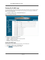
Viewing the FLASH Logs ............................................................................................................ 204
Clearing FLASH Logs ........................................................................................................................... 204
Defining Servers Log Parameters ............................................................................................... 205
Managing Device Diagnostics............................................................................................. 206
Configuring Port Mirroring ........................................................................................................... 207
Viewing Integrated Cable Tests .................................................................................................. 209
Viewing Optical Transceivers...................................................................................................... 210
Viewing the CPU Utilization ........................................................................................................ 211
Configuring System Time.................................................................................................... 212
Configuring Daylight Savings Time ............................................................................................. 213
Configuring SNTP ....................................................................................................................... 217
Polling for Unicast Time Information ..................................................................................................... 217
Polling for Anycast Time Information .................................................................................................... 217
Broadcast Time Information.................................................................................................................. 217
Defining SNTP Global Settings ................................................................................................... 219
Page 4
Defining SNTP Authentication .....................................................................................................221
Defining SNTP Servers ...............................................................................................................223
Defining SNTP Interface Settings................................................................................................225
Viewing Statistics ................................................................................................................ 227
Viewing Interface Statistics..........................................................................................................227
Viewing Device Interface Statistics........................................................................................................228
Resetting Interface Statistics Counters..................................................................................................229
Viewing Etherlike Statistics....................................................................................................................229
Resetting Etherlike Statistics Counters..................................................................................................230
Viewing GVRP Statistics........................................................................................................................231
Resetting GVRP Statistics Counters .....................................................................................................232
Viewing EAP Statistics...........................................................................................................................232
Managing RMON Statistics .........................................................................................................233
Viewing RMON Statistics.......................................................................................................................234
Resetting RMON Statistics Counters.....................................................................................................235
Configuring RMON History ....................................................................................................................236
Defining RMON Alarms .........................................................................................................................243
Problem Management .................................................................................................................246
Troubleshooting Solutions ...........................................................................................................246
Contacting D-Link Technical Support ..........................................................................................249
Warranty ......................................................................................................................................276
Product Registration ....................................................................................................................279
International Offices.....................................................................................................................280
Page 5
D-Link DES-3010FA/GA User Guide
Preface
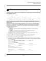
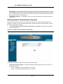
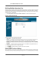
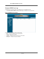
The Embedded Web System (EWS) is a network management system. The D-Link Embedded Web Interface configures, monitors, and troubleshoots network devices from a remote web browser. The D-Link Embedded Web
Interface web pages are easy-to-use and easy-to-navigate. In addition, The D-Link Embedded Web Interface provides real time graphs and RMON statistics to help system administrators monitor network performance.
This preface provides an overview to the D-Link Embedded Interface User Guide, and includes the following sections:
•
•
D-Link DES-3010FA/GA User Guide Overview
Intended Audience
Page 6
Preface
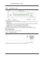
D-Link DES-3010FA/GA User Guide Overview
D-Link DES-3010FA/GA User Guide Overview
This user guide is divided into the following sections to provide concise information for installing, configuring, and
managing the device:
•
•
Using the Installation Guide
Using the Embedded Web Interface User Guide
Using the Installation Guide
This section provides an overview of the D-Link 3010FA/GA Installation Guide, which includes the following sections:
•
•
•
Section 1. Device Description — Provides a system description including the hardware components.
Section 2. Mounting Device — Provides step-by-step instructions for installing the device.
Section 3. Starting and Configuring the Device — Provides step-by-step instructions for the initial device
configuration.
Using the Embedded Web Interface User Guide
This section provides an overview to the D-Link Web System Interface User Guide. The D-Link Web System Interface User Guide provides the following sections:
•
•
•
•
•
•
•
•
•
•
•
•
•
•
•
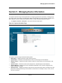
Section 4. Getting Started — Provides information about using the EWS, including The D-Link Embedded
Web Interface interface, management, and information buttons, as well as information about adding, modifying, and deleting device information.
Section 5. Managing Device Information — Provides information about opening the device zoom view and
defining general system information.
Section 6. Configuring Device Security — Provides information about configuring device security for management security, traffic control, and network security.
Section 7. Configuring Ports — Provides information about configuring ports.
Section 8. Aggregating Ports — Provides information about configuring Link Aggregated Groups and
LACP.
Section 9. Configuring VLANs — Provides information about configuring and managing VLANs, including
information about GARP and GVRP.
Section 10. Configuring IP Information — Provides information about defining device IP addresses, ARP,
and Domain Name Servers.
Section 11. Defining the Forwarding Database — Provides information about configuring and managing
both static and dynamic MAC addresses.
Section 12. Configuring Spanning Tree — Provides information about configuring Spanning Tree Protocol
and the Rapid Spanning Tree Protocol.
Section 13. Configuring Multicast Forwarding — Provides information about Multicast Forwarding.
Section 14. Configuring SNMP — Provides information about defining SNMP v1,v2c, and v3 management,
including SNMP filters and notifications.
Section 15. Configuring Quality of Service — Provides information about configuring Quality of Service on
the device.
Section 16. Managing System Files — Provides information about downloading, uploading, and copying
system files.
Section 17. Managing System Logs — Provides information about enabling and defining system logs.
Section 18. Managing Device Diagnostics — Provides information about configuring port mirroring, testing
copper and fiber cables, and viewing device health information.
Page 7
D-Link DES-3010FA/GA User Guide
•
•
•
Section 19. Configuring System Time — Provides information about configuring system time, including
Daylight Savings Time parameters and Simple Network Time Protocol (SNTP) parameters.
Section 20. Viewing Statistics — Provides information about viewing device statistics, including RMON statistics, device history events, and port and LAG utilization statistics.
Appendix A, Troubleshooting — Provides basic troubleshooting for installing the device.
Intended Audience
This guide is intended for network administrators familiar with IT concepts and terminology.
Page 8
D-Link DES 3010FA/GA Installation Guide
D-Link DES 3010FA/GA Installation Guide
Page 9
D-Link DES-3010FA/GA User Guide
Section 1. Device Description
This section contains a description of the D-Link DES-3010FA and D-Link DES-3010GA, and contains the
following topics:
•
•
•
•
•
•
Viewing the Device
Ports Description
Cable Specifications
LED Defiitions
Cable, Port, and Pinout Information
Physical Dimensions
Page 10
Device Description
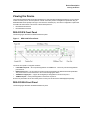
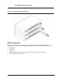
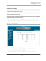
Viewing the Device
Viewing the Device
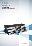
The D-Link DES-3010FA and D-Link DES-3010GA are 10 port Fast Ethernet Managed Switches. The two devices
contain 8 network ports on the front panel for network connectivity. Device management is performed using an
Embedded Web Server (EWS) or through a Command Line Interface (CLI). The device configuration is performed
via a DB-9 RS-232 interface. This section contains descriptions for:
•
•
DES-3010FA Front Panel
DES-3010GA Front Panel
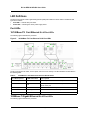
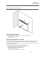
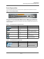
DES-3010FA Front Panel
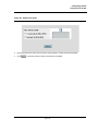
The following figure illustrates the DES-3010FA front panel.
Figure 1:
DES-3010FA Front Panel
The device front panel is configured as follows:
•
8 Fast Ethernet ports — RJ-45 ports designated as 10/100Base-TX . The RJ-45 ports are designated as
ports Ports1-8.
•
DB-9 Console port — An asynchronous serial console port supporting the RS-232 electrical specification.
The port is used to connect the device to the console managing the device.
•
1000Base-T Copper port — Copper RJ-45 Gigabit port designated on the device as port 9.
•
100Base-FX port — Fiber port designated on the device as ports 10.
On the front panel there are the Port activity LEDs on each port and the Power LED displayed separately.
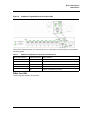
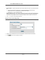
DES-3010GA Front Panel
The following figure illustrates the DES-3010GA front panel.
Page 11
D-Link DES-3010FA/GA User Guide
Figure 2:
DES-3010GA Front Panel
The device front panel is configured as follows:
•
8 Fast Ethernet ports — RJ-45 ports designated as 10/100Base-TX . The RJ-45 ports are designated as
ports Ports1-8.
•
DB-9 Console port — An asynchronous serial console port supporting the RS-232 electrical specification.
The port is used to connect the device to the console managing the device.
•
1000Base-T port — RJ-45 Gigabit port designated on the device as port 9.
•
SFP Port — There is one SFP port, which contains 1000Base-X (fiber) connections.
On the front panel there are the Port activity LEDs on each port and the Power LED displayed separately.
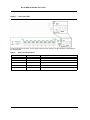
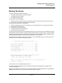
DES-3010 Back Panel
The following figure illustrates the DES-3010 back panel.
Figure 3:
DES-3010 Back Panel
The DES-3010 device back panel contains a AC power supply interface.
Page 12
Device Description
Ports Description
Ports Description
This section describes the device ports and includes the following topics:
•
•
•
•
•
10/100Base-TX Fast Ethernet Ports
1000Base-T Gigabit Ethernet Ports
100Base-FX Fiber port
SFP Port
DB-9 Console Port
10/100Base-TX Fast Ethernet Ports
The 10/100Base-TX Fast Ethernet ports are RJ-45.
1000Base-T Gigabit Ethernet Ports
The device contains a 1000 Base-TX Gigabit port. The port is an RJ-45 port which supports half- and full-duplex
mode 10/100/1000 Mbps.
100Base-FX Fiber Ports
The 100Base-FX Fast Ethernet port in the DES-3010FA device is a Fiber ports.
SFP Port
Small Form Factor Pluggable (SFP) Optical Transceivers are integrated duplex data GBIC links for bi-directional
communication over multimode optical fiber, designed for high-speed Fiber Channel data links. The SFP port is
designated as 1000Base-X.
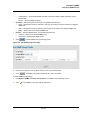
The SFP (GBIC) port can be removed and inserted as required. The following figure illustrates the GBIC insertion.
Page 13
D-Link DES-3010FA/GA User Guide
Figure 4:
Inserting a GBIC into the Device
DB-9 Console Port
The DB-9 port is an asynchronous serial console port supporting the RS-232 electrical specification. The port is
used to connect the device to a console managing the device. This interface configuration is as follows:
•
•
•
•
•
Eight data bits.
One stop bit.
No parity.
Baud rate is 9600 (default). The user can change the rate from 115200 down to 9600 bps.
Console speeds of 57600 and 115200.
Page 14
Device Description
Cable Specifications
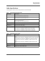
Cable Specifications
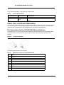
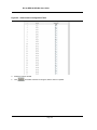
The following table contains the various cable specification for the DES-3010FA/GA:
Table 1:
DES-3010FA/GA Cable Specifications
Cab le Typ e
D escr ip tio n
10Base-TX
UTP Category 3, 4, 5 (100 meters max.)
EIA/TIA- 568 150-ohm STP (100 meters max.)
100Base-TX
UTP Cat. 5 (100 meters max.)
EIA/TIA-568 150-ohm STP (100 meters max.)
1000Base-T
UTP Cat. 5e (100 meters max.)
UTP Cat. 5 (100 meters max.)
EIA/TIA-568B 150-ohm STP (100 meters max.)
1000BASE-LX
Single-mode fiber module (10km)
1000BASE-SX
Multi-mode fiber module (550m)
1000BASE-LH
Single-mode fiber module (40km)
1000BASE-ZX
Single-mode fiber module (80km)
Mini-GBIC
SFP Transceiver for 1000BASE-LX Single-mode fiber module (10km)
SFP Transceiver for 1000BASE-SX Multi-mode fiber module (550m)
SFP Transceiver for 1000BASE-LH Single-mode fiber module (40km)
SFP Transceiver for 1000BASE-ZX Single-mode fiber module (80km)
:
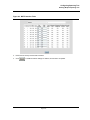
Table 2:
DES-3010FA/GA Cable Lengths
Cab le Typ e
D escr ip tio n
DEM-310GT: SFP Transceiver for 1000BASE-LX, Single-mode fiber module
10km
DEM-311GT: SFP Transceiver for 1000BASE-SX, Multi-mode fiber module 550m
DEM-312GT2: SFP Transceiver for 1000BASE-SX+, Multi-mode module 2km
DEM-314GT: SFP Transceiver for 1000BASE-LH, Single-mode fiber module
50km
DEM-315GT: SFP Transceiver for 1000BASE-ZX, Single-mode fiber module
80km
1000Base-T
Category 5e UTP CableCategory 5 UTP Cable(1000 Mbps) 100m
100Base-TX
Category 5 UTP Cable (100 Mbps) 100m
10Base-TX
Category 3 UTP Cable (10 Mbps) 100m
Page 15
D-Link DES-3010FA/GA User Guide
LED Defiitions
The device front panels contain Light Emitting Diodes (LED) that indicate the device status.The different LED
types are as follows:
•
Port LEDs — Indicate each port status.
•
Power LED — Indicating the device power supply status.
Port LEDs
10/100Base-TX Fast Ethernet RJ-45 Port LEDs
The following figure illustrates the port LEDs.
Figure 5:
10/100Base-TX Fast Ethernet RJ-45 Port LEDs
The RJ-45 ports have two LEDs, one for speed, and one for Link /activity. The LED indications are described in
the following table:
Table 3:
10/100Base-TX Fast Ethernet RJ-45 Port LED Indications
Por t Des criptio n
L ED In dica tio n
D escr ip tio n
Left LED - Speed
Green
A 100-Mbps link is established on the port.
Off
A 10-Mbps link is established on the port or no link is established on the port.
Green
A link is established on the port.
Flashing Green
There is data transmission on the port.
Off
No link is established on the link.
Link/Activity LED
1000Base-T Gigabit Ethernet RJ-45 Port LEDs
The following figure illustrates the port LEDs.
Page 16
Device Description
LED Defiitions
Figure 6:
1000Base-T Gigabit Ethernet RJ-45 Port LEDs
The RJ-45 ports have two LEDs, one for speed, and one for Link /activity. The LED indications are described in
the following table:
Table 4:
1000Base-T Gigabit Ethernet RJ-45 Port LED Indications
Por t Des criptio n
L ED In dica tio n
D escr ip tio n
Left LED - Speed
Green
A 100/1000-Mbps link is established on the port.
Off
No link is established on the port.
Green
A link is established on the port.
Flashing Green
There is data transmission on the port.
Off
No link is established on the link.
Link/Activity LED
Fiber Port LEDs
The following figure illustrates the port LEDs.
Page 17
D-Link DES-3010FA/GA User Guide
Figure 7:
Fiber Port LEDs
The RJ-45 ports have two LEDs, one for speed, and one for Link /activity. The LED indications are described in
the following table:
Table 5:
Fiber Port LED Indications
Por t Des criptio n
L ED In dica tio n
D escr ip tio n
Left LED - Speed
Green
A 100/1000-Mbps link is established on the port.
Off
No link is established on the port.
Green
A link is established on the port.
Flashing Green
There is data transmission on the port.
Off
No link is established on the link.
Link/Activity LED
Page 18
Device Description
LED Defiitions
SFP Port LEDs
The following figure illustrates the port LEDs.
Figure 8:
SFP Port LEDs
The RJ-45 ports have two LEDs, one for speed, and one for Link /Activity. The LED indications are described in
the following table:
Table 6:
SFP Port LED Indications
Por t Des criptio n
L ED In dica tio n
D escr ip tio n
Left LED - Speed
Green
A 100/1000-Mbps link is established on the port.
Off
No link is established on the port.
Green
A link is established on the port.
Flashing Green
There is data transmission on the port.
Off
No link is established on the link.
Link/Activity LED
Power LED
The power supply status is indicated by the Power Supply LED on the front panel of the device.
The power supply port LED indications are described in the following table:
Table 7:
Power Supply LED Indications
Por t D escr ip tio n
L ED In dica tio n
D escr ip tio n
Power
Off
The system is not powered up. (power off)
Green
Main power is functional (normal operation)
Console LED
The console status is indicated by the Console LED on the front panel of the device.
Page 19
D-Link DES-3010FA/GA User Guide
The console LED indications are described in the following table:
Table 8:
Console LED Indications
Por t D escr ip tio n
L ED In dica tio n
D escr ip tio n
Console
Flashing Green
Power On Self Test (POST) is in progress.
Green
POST failure. A problem has been discovered during the
POST.
Cable, Port, and Pinout Information
This section describes the devices physical interfaces and provides information about cable connections. Stations
are connected to the device ports through the physical interface ports on the front panel. For each station, the
appropriate mode (Half/Full Duplex, Auto Negotiation) is set. The default is Auto Negotiation.
Pin Connections for the 10/100/1000 Ethernet Interface
The switching port can connect to stations wired in standard RJ-45 Ethernet station mode using straight cables.
Transmission devices connected to each other use crossed cables. The following figure illustrates the pin
allocation.
Figure 9:
RJ-45 Pin Allocation
The following table describes the pin allocation
Table 9:
RJ-45 Pin Connections for 10/100/1000 Base-TX
Pin
U se
1
TxRx 1+
2
TxRx 1-
3
TxRx 2+
4
TxRx 2-
5
TxRx 3+
6
TxRx 3-
7
TxRx 4+
8
TxRx 4-
Page 20
Device Description
Physical Dimensions
Physical Dimensions
The device has the following physical dimensions:
•
Width: 220 mm (8.66 inch)
•
Depth: 155mm (6.10 inch)
•
Height: 35 mm (1.38 inch)
Page 21
DLINK DES-3010FA/GA User Guide
Section 2. Mounting Device
This section contains information for installing the device, and includes the following sections:
•
•
•
•
•
Preparing for Installation
Installing the Device
Connecting the Device
Rack Installation
Wall Installation
Page 22
Mounting Device
Preparing for Installation
Preparing for Installation
This section provides an explanation for preparing the installation site, and includes the following topics:
•
•
•
Installation Precautions
Site Requirements
Unpacking
Installation Precautions
Warnings
•
•
•
•
•
•
•
•
•
•
The surface on which the switch is placed should be adequately secured to prevent it from becoming
unstable and/or falling over.
Ensure the power source circuits are properly grounded.
Observe and follow service markings. Do not service any product except as explained in your system
documentation. Opening or removing covers marked with a triangular symbol with a lighting bolt may
cause electrical shock. These components are to be serviced by trained service technicians only.
Ensure the power cable, extension cable, and/or plug is not damaged.
Ensure the product is not exposed to water.
Ensure the device is not exposed to radiators and/or heat sources.
Do not push foreign objects into the device, as it may cause a fire or electric shock.
Use the device only with approved equipment.
Allow the product to cool before removing covers or touching internal equipment.
Ensure the switch does not overload the power circuits, wiring, and over-current protection. To determine the possibility of overloading the supply circuits, add together the ampere ratings of all devices
installed on the same circuit as the device being installed. Compare this total with the rating limit for
the circuit. The maximum ampere ratings are usually printed on the switch, near their AC power connectors.
Cautions
•
•
•
Ensure the air flow around the front, sides, and back of the switch is not restricted.
Ensure the cooling vents are not blocked.
Do not install the switch in an environment where the operating ambient temperature might exceed
40ºC (104ºF).
Site Requirements
The device is placed on a table-top. Before installing the unit, verify that the location chosen for installation meets
the following site requirements.
•
General — Ensure that the power supply is correctly installed.
•
Power — The unit is installed within 1.5 m (5 feet) of a grounded, easily accessible outlet 100-250 VAC, 5060 Hz.
•
Clearance — There is adequate frontal clearance for operator access. Allow clearance for cabling, power
connections and ventilation.
•
Cabling — The cabling is routed to avoid sources of electrical noise such as radio transmitters, broadcast
amplifiers, power lines and fluorescent lighting fixtures.
Page 23
DLINK DES-3010FA/GA User Guide
•
Ambient Requirements — The ambient unit operating temperature range is 0 to 40ºC (32 to 104ºF) at a
relative humidity of up to 95%, non-condensing. Verify that water or moisture cannot enter the device casing.
Unpacking
This section contains information for unpacking the device, and includes the following topics:
•
•
Package Contents
Unpacking Essentials
Package Contents
While unpacking the device, ensure that the following items are included:
•
The device
•
Four rubber feet with adhesive backing
•
Rack kit
•
An AC power cable
•
Console RS-232 cable with DB-9 connector
•
Documentation CD
Unpacking Essentials
Note
Before unpacking the device, inspect the package and report any evidence of damage immediately.
To unpack the device perform the following:
1. It is recommended to put on an ESD wrist strap and attach the ESD clip to a metal surface to act as ground.
An ESD strap is not supplied with the device.
2. Place the container on a clean flat surface and cut all straps securing the container.
3. Open the container.
4. Carefully remove the device from the container and place it on a secure and clean surface.
5. Remove all packing material.
6. Inspect the product for damage. Report any damage immediately.
If any item is found missing or damaged, please contact your local D-Link reseller for replacement.
Page 24
Mounting Device
Installing the Device
Installing the Device
The device can be installed on a flat surface or mounted in a rack. This section includes the following topics:
•
•
Desktop or Shelf Installation
Rack Installation
Desktop or Shelf Installation
When installing the switch on a desktop or shelf, the rubber feet included with the device should first be attached.
Attach these cushioning feet on the bottom at each corner of the device.
Ensure the surface is be able to support the weight of the device and the device cables.
To install the device on a surface, perform the following:
1. Attach the rubber feet on the bottom of the device. The following figure illustrates the rubber feet installation
on the device.
Figure 10: Installing Rubber Feet
2.
3.
Set device down on a flat surface, while leaving 2 inches on each side and 5 inches at the back.
Ensure that the device has proper ventilation by allowing adequate space for ventilation between the device
and the objects around the device.
Rack Installation
The device can be mounted in an EIA standard-sized, 19-inch rack, which can be placed in a wiring closet with
other equipment. To install, the device the mounting brackets must first be attached on the devices’s sides.
Page 25
DLINK DES-3010FA/GA User Guide
Notes
• Disconnect all cables from the unit before mounting the device in a rack or cabinet.
• When mounting multiple devices into a rack, mount the devices from the bottom up.
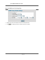
To install the device in a rack, perform the following:
1. Place the supplied rack-mounting bracket on one side of the device ensuring the mounting holes on the
device line up to the mounting holes on the rack mounting bracket. The following figure illustrates where to
mount the brackets.
Figure 11: Attaching the Mounting Brackets
2.
3.
4.
Insert the supplied screws into the rack mounting holes and tighten with a screwdriver.
Repeat the process for the rack-mounting bracket on the other side of the device.
Insert the unit into the 19-inch rack ensuring the rack-mounting holes on the device line up to the mounting
hole on the rack. The following figure illustrates lining up and mounting the device in the rack.
Page 26
Mounting Device
Installing the Device
Figure 12: Mounting Device in a Rack
5.
Secure the unit to the rack with the rack screws (not provided). Fasten the lower pair of screws before the
upper pair of screws. This ensures that the weight of the unit is evenly distributed during installation. Ensure
that the ventilation holes are not obstructed.
Page 27
DLINK DES-3010FA/GA User Guide
Wall Installation
The device can also be mounted on a wall inside a wiring closet.
To mount the device on a wall, perform the following:
1.
2.
3.
4.
Mark two holes 100mm apart on the wall.
Drill holes into the wall where the marks have been made. The hole diameter and depth is defined by the wall
plug and screw combination being used to mount the device.
Insert the wall plugs unto the holes.
Screw the screws into the wall plugs allowing the heads to protrude from the wall. The device is mounted on
the protruded heads.
Figure 13: Inserting wall plugs and screws
Wall
Drilled Hole
Drilled Hole
5.
Align the mounting holes on the back of the device with the screws in the wall, and mount the device on the
wall.
Page 28
Mounting Device
Connecting the Device
Figure 14: Mounting the device on the wall
Wall
Connecting the Device
This section describes how to connect the device, and includes the following sections:
•
Connecting the Switch to a Terminal
•
AC Power Connection
Connecting the Switch to a Terminal
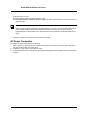
The device is connected to a terminal through an console port on the front panel, which enables a connection to a
terminal desktop system running terminal emulation software for monitoring and configuring the device.
The terminal must be a VT100 compatible terminal or a desktop or portable system with a serial port and running
VT100 terminal emulation software.
To connect a terminal to the device Console port, perform the following:
1. Connect a cable to the terminal running VT100 terminal emulation software.
2. Ensure that the terminal emulation software is set as follows:
a) Select the appropriate port to connect to the device.
b) Set the data rate to 9600 baud.
c) Set the data format to 8 data bits, 1 stop bit, and no parity.
Page 29
DLINK DES-3010FA/GA User Guide
d) Set flow control to none.
e) Under Properties, select VT100 for Emulation mode.
f) Select Terminal keys for Function, Arrow, and Ctrl keys. Ensure that the setting is for Terminal keys (not
Windows keys).
Note
When using HyperTerminal with Microsoft Windows 2000, ensure that you have Windows 2000 Service
Pack 2 or later installed. With Windows 2000 Service Pack 2, the arrow keys function properly in
HyperTerminal’s VT100 emulation. Go to www.microsoft.com for information on Windows 2000 service
packs.
3.
Connect the cable to the console port on the device front panel.
AC Power Connection
To connect the power supply perform the following:
1. Using a 5-foot (1.5 m) standard power cable with safety ground connected, connect the power cable to the
AC main socket located on the back panel.
2. Connect the power cable to a grounded AC outlet.
3. Confirm that the device is connected and operating by checking that the Power Supply LED on the front panel
is green.
Page 30
Starting and Configuring the Device
Section 3. Starting and Configuring the Device
This section describes initial device configuration and includes the following topics:
•
Configuring the Terminal
•
Installation Procedure
•
Booting the Device
•
Configuration Overview
•
Advanced Configuration
•
Startup Procedures
Page 31
D-Link DES-3010FA/GA User Guide
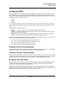
Configuring the Terminal
After completing all external connections, connect a terminal to the device to monitor the boot and other
procedures.
To configure the device, the terminal must be running terminal emulation software.
Ensure that the terminal emulation software is configured as follows:
1.
2.
3.
4.
5.
Connect the Chassis serial port to the switch module. The baud rate automatically boots up at 9600.
Set the data format to 8 data bits, 1 stop bit, and no parity.
Set Flow Control to none.
Under Properties, select VT100 for Emulation mode.
Select Terminal keys for Function, Arrow, and Ctrl keys. Ensure that the setting is for Terminal keys (not
Windows keys).
Note
When using HyperTerminal with Microsoft® Windows 2000, make sure that Windows® 2000 Service
Pack 2 or later is installed. With Windows 2000 Service Pack 2, the arrow keys function properly in
HyperTerminal’s VT100 emulation. Go to www.microsoft.com for information on Windows 2000 service
packs.
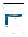
Installation Procedure
The order of installation and configuration procedures is illustrated in the following figure. For the initial
configuration, the standard device configuration is performed.
Performing other functions is described later in this section.
Device Port Default Settings
The following table describes the device port default settings.
Table 10:
Port Default Setting
Fu nc tio n
De fa ul t Se tti n gs
Port speed and mode
100M Auto-negotiation
Port forwarding state
Enabled
Head of line blocking prevention
On (Enabled)
Flow Control
Off
Back Pressure
Off
Note
These default settings can be modified once the device is installed.
Page 32
Starting and Configuring the Device
Booting the Device
Booting the Device
The assumed bootup information is as follows:
•
•
The device is delivered with a default configuration.
The default user name is admin
•
The default passwordis blank.
To login, perform the following steps:
1. Press Enter twice in rapid succession. The auto baud-rate process synchronizes the host and the device.
2. Enter the user name, admin. The default password is blank.
To boot the device, perform the following steps:
1.
2.
3.
4.
5.
Ensure that the device port console is connected to a VT100 terminal device or VT100 terminal emulator.
Locate an AC power receptacle.
Deactivate the AC power receptacle.
Connect the device to the AC receptacle.
Activate the AC power receptacle.
The device goes through Power On Self Test (POST). POST runs every time the device is initialized and checks
hardware components to determine if the device is fully operational before completely booting. If a critical problem
is detected, the program flow stops. If POST passes successfully, a valid executable image is loaded into RAM.
POST messages are displayed on the terminal and indicate test success or failure.
As the device boots, the bootup test first counts the device memory availability and then continues to boot. The
following screen is an example of the displayed POST:
------ Performing the Power-On Self Test (POST) -----UART Channel Loopback Test........................PASS
Testing the System SDRAM..........................PASS
Boot1 Checksum Test...............................PASS
Boot2 Checksum Test...............................PASS
Flash Image Validation Test.......................PASS
FRU Validation Test...............................PASS
BOOT Software Version x.x.x.xx Built 22-Jan-2005 15:09:28
Processor: xxxxxx xxxxx , xxx MByte SDRAM.
I-Cache x KB. D-Cache x KB. Cache Enabled.
Autoboot in 2 seconds - press RETURN or Esc. to abort and enter prom.
Preparing to decompress...
The boot process runs for approximately 60 seconds.
The auto-boot message displayed at the end of POST (see the last lines) indicates that no problems were
encountered during boot.
During boot, the Startup menu can be used to run special procedures. To enter the Startup menu, press <Esc> or
<Enter> within the first two seconds after the auto-boot message is displayed.
Page 33
D-Link DES-3010FA/GA User Guide
If the system boot process is not interrupted by pressing <Esc> or <Enter>, the process continues
decompressing and loading the code into RAM. The code starts running from RAM and the list of numbered
system ports.
After the device boots successfully, a system prompt is displayed (console>) which is used to configure the
device. However, before configuring the device, ensure that the latest software version is installed on the device. If
it is not the latest version, download and install the latest version. For more information on downloading the latest
version, see Software Download and Reboot.
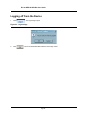
Configuration Overview
Before assigning a static IP address to the device, obtain the following information:
•
A specific IP address that has been allocated to the device in order for it to be configured.
•
A default route.
•
A network mask for the network.
There are two configuration types:
•
Initial Configuration — Consists of configuration functions with basic security considerations.
•
Advanced Configuration — Consists of dynamic IP configuration and more advanced security considerations.
Note
After making any configuration changes, the new configuration must be saved before rebooting. To save
the configuration, enter:
console# copy running-config startup-config
Initial Configuration
Initial configuration, which starts after the device has booted successfully, includes static IP address and subnet
mask configuration, and setting user names and privilege levels to allow remote management. If the device is to
be managed from an SNMP-based management station, SNMP community strings must also be configured.
The following configurations are completed, and the initial configuration uses the following assumptions:
•
The device was never configured before, and is in the same state as when it was received.
•
The device booted successfully.
•
The Serial connection is established and the console prompt is displayed on the screen of a VT100 terminal
device. (Press <Enter> several times to verify that the prompt displays correctly.)
•
The device is not configured with a default user name and password.
The initial device configuration is through the Serial port. After the initial configuration, the device can then be
managed either from the already connected Serial port or remotely through an interface defined during the initial
configuration.
During the initial configuration, you can:
•
Configure a user name, a password, and the highest privilege level of 15.
•
Configure the static IP address and the default gateway.
•
Configure the SNMP read/write community string.
•
Assign the IP address allocated by the DHCP server.
Before applying the initial configuration procedure to the device, the following information must be obtained from
the network administrator:
•
The IP address to be assigned to a VLAN through which the device is managed.
•
The IP subnet mask for the network.
Page 34
Starting and Configuring the Device
Configuration Overview
•
•
The default gateway IP address.
The SNMP community.
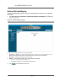
Static IP Address and Subnet Mask
IP interfaces can be configured on each port of the device. After entering the configuration command, it is
recommended to check if a port was configured with the IP address by entering the show ip interface
command.
Note
The commands to configure the device are port specific.
To manage the switch from a remote network, a static route must be configured, which is an IP address to where
packets are sent when no entries are found in the device tables. The configured IP address must belong to the
same subnet as one of the device IP interfaces.
To configure a static route, enter the command at the system prompt, as shown in the following configuration
example, where 100.1.1.1 is the specific management station, the IP address is defined on VLAN 1, and the
default gateway is defined as 100.1.1.10. Note that by default, all ports are members of VLAN 1, which is the
default VLAN.
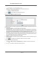
console# configure
console(config)# interface vlan 1
console(config-if)# ip address 100.1.1.1 255.255.255.0
console(config-if)# exit
console# default-gateway 100.1.1.10 255.255.255.0
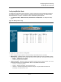
Confirm that the IP address has been correctly configured as follows:
console# show ip interface
Proxy ARP is disabled
IP Address
I/F
Type
---------------------------100.1.1.1/24
vlan 1
static
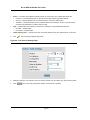
Assigning Static IP Addresses on a Default VLAN
This example uses the following assumptions:
•
The IP address to be assigned to the VLAN interface is 100.1.1.110
•
The IP subnet mask for the network is 255.255.255.0
•
The IP address of the default route is 192.168.1.1
•
The read/write SNMP community string is "private"
console> enable
console# configure
console(config)# username admin password dlink level 15
console(config)# interface VLAN 1
console (config-if) # ip address 100.1.1.110
console (config-if) # exit
Page 35
D-Link DES-3010FA/GA User Guide
console (config) # ip default-gateway 100.1.1.110
console (config) # snmp-server community private rw
console(config)# exit
console#
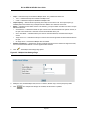
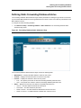
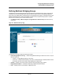
Verifying the IP and Default Gateway Addresses
To ensure that the IP address and the default gateway were properly assigned, execute the following command
and examine its output:
console # - ip interface
Gateway IP Address
Activity status
--------------------- --------------192.168.1.1
Active
IP address
-------------192.168.1.123/24
Interface
----------VLAN 1
Type
-----Static
User Name
A user name is used to manage the device remotely, for example through SSH, Telnet, or the Web interface. To
gain complete administrative (super-user) control over the device, the highest privilege (15) must be specified.
Note
Only the administrator (super-user) with the highest privilege level (15) is allowed to manage the device
through the web browser interface.
For more information about the privilege level, see the CLI Reference Guide.
The configured user name is entered as a login name for remote management sessions. To configure a user
name, password, and privilege level, enter the command at the system prompt as shown in the configuration
example:
console> enable
console# configure
console(config)# username admin password lee privilege 15
SNMP Community Strings
Simple Network Management Protocol (SNMP) provides a method for managing network devices. Devices
supporting SNMP run a local software agent. The SNMP agents maintain a list of variables, used to manage the
device. The variables are defined in the Management Information Base (MIB). The SNMP agent defines the MIB
specification format, as well as the format used to access the information over the network.
Access rights to the SNMP agents are controlled by access strings and SNMP community strings.
The device is SNMP-compliant, and contains an SNMP agent that supports a set of standard and private MIB
variables. Developers of management stations require the exact structure of the MIB tree and receive the
complete private MIBs information before being able to manage the MIBs.
All parameters are manageable from any SNMP management platform, except the SNMP management station IP
address and community (community name and access rights). The SNMP management access to the switch is
disabled if no community strings exist.
Page 36
Starting and Configuring the Device
Configuration Overview
Note
The device is delivered with no community strings configured.
The community-string, community-access, and IP address can be configured through the local terminal during the
initial configuration procedure.
The SNMP configuration options are:
•
Community string
–
–
Access rights options: ro (read only), rw (read-and-write), and su (super).
An option to configure IP address or not. If an IP address is not configured, it means that all community
members having the same community name are granted the same access rights.
Common practice is to use two community strings for the device, one (public community) with read-only access
and the other (private community) with read-write access. The public string allows authorized management
stations to retrieve MIB objects, while the private string allows authorized management stations to retrieve and
modify MIB objects.
During initial configuration, it is recommended to configure the device according to the network administrator
requirements, in accordance with using an SNMP-based management station. During the initial configuration
procedure, the community-string, community-access, and IP address can be set through the local terminal.
The SNMP configuration options are:
Community string.
•
•
–
Read Only — Community members can view configuration information, but cannot change any
information.
–
–
Read/Write — Community members can view and modify configuration information.
Super — Community members have administration access.
Configurable IP address. If an IP address is not configured, all community members with the same
community name are granted the same access rights.
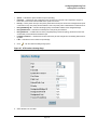
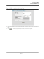
To configure an SNMP station IP address and community string(s), perform the following steps:
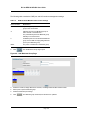
1. At the console prompt, enter the command Enable. The prompt is displayed as #.
2. Enter the command configure and press <Enter>.
3. In configuration mode, enter the SNMP configuration command with the parameters including community
name (private), community access right (read and write), and IP address, as shown in the following example:
console# configure
config(config)# snmp-server community private rw 11.1.1.2 type router
config(config)# exit
console(config)# show snmp
Community-String
Community-Access
IP address
-------------------------------------------------- -------------------private
readWrite
11.1.1.2
Traps are enabled.
Authentication-failure trap is enabled.
Trap-Rec-Address
-----------------------System
Trap-Rec-Community
Version
--------------------------- --------------------
Page 37
D-Link DES-3010FA/GA User Guide
Contact:
System Location:
This completes the initial configuration of the device from a local terminal. The configured parameters enable
further device configuration from any remote location.
Page 38
Starting and Configuring the Device
Advanced Configuration
Advanced Configuration
This section provides information about dynamic allocation of IP addresses and security management based on
the authentication, authorization, and accounting (AAA) mechanism, and includes the following topics:
•
•
•
Receiving an IP Address from a DHCP Server
Receiving an IP Address from a BOOTP Server
Security Management and Password Configuration
When configuring or receiving IP addresses through DHCP and BOOTP, the configuration received from these
servers includes the IP address, and may include a subnet mask and default gateway.
Receiving an IP Address from a DHCP Server
When using the DHCP protocol to retrieve an IP address, the device acts as a DHCP client. To receive an IP
address from a DHCP server, perform the following steps:
1.
2.
3.
Select and connect any port to a DHCP server or to a subnet that has a DHCP server on it, in order to retrieve
the IP address.
Enter the following commands to use the selected port for receiving the IP address. In the following example,
the commands are based on the port type used for configuration.
console# configure
console(config)# interface ethernet 1
console(config-if)# ip address dhcp hostname admin-host
console(config-if)# exit
console(config)#
To verify the IP address, enter the show ip interface command at the system prompt as shown in the
following example.
console# show ip interface
IP Address
I/F
Type
-------------------------------100.1.1.1/24
vlan 1
dynamic
Notes
•
•
The device configuration does not have to be deleted to retrieve an IP address for the DHCP server.
When copying configuration files, avoid using a configuration file that contains an instruction to
enable DHCP on an interface that connects to the same DHCP server, or to one with an identical configuration. As a result of the copying configuration, the switch retrieves the new configuration file and
boots from it. The device then enables DHCP as instructed in the new configuration file, and the
DHCP instructs it to reload the same file.
Receiving an IP Address from a BOOTP Server
The standard BOOTP protocol is supported and enables the switch to automatically download its IP host
configuration from any standard BOOTP server in the network. In this case, the device acts as a BOOTP client.
To receive an IP address from a BOOTP server:
1.
2.
Select and connect any port to a BOOTP server or subnet containing such a server.
At the system prompt, enter the delete startup configuration command to delete the startup configuration
from flash.
Page 39
D-Link DES-3010FA/GA User Guide
The device reboots with no configuration and in 60 seconds starts sending BOOTP requests. The device
receives the IP address automatically.
Note
When the device reboot begins, any input at the ASCII terminal or keyboard automatically cancels the
BOOTP process before completion, and the device does not receive an IP address from the BOOTP
server.
The following example illustrates the process:
3.
console# enable
console# delete startup-config
Startup file was deleted
console# reload
You haven’t saved your changes. Are you sure you want to continue (y/n)[n]?
This command will reset the whole system and disconnect your current session.Do you want
to continue (y/n)[n]?
******************************************************
/*the device reboots */
To verify the IP address, enter the show ip interface command. The device is now configured with an IP
address.
Security Management and Password Configuration
System security is handled through the AAA (Authentication, Authorization, and Accounting) mechanism that
manages user access rights, privileges, and management methods. AAA uses both local and remote user
databases. Data encryption is handled through the SSH mechanism.
The system is delivered with the user name admin, and no default password configured; all user names and
passwords are user-defined. If a user-defined user name and/or password is lost, a password recovery procedure
can be initiated from the Startup menu. The procedure is applicable for the local terminal only and allows a onetime access to the device from the local terminal with no password entered.
The security passwords can be configured for the following services:
•
•
•
•
•
Console
Telnet
SSH
HTTP
HTTPS
Note
When creating a user name, the default priority is 1, which allows access but not configuration rights. A
priority of 15 must be set to enable full access and configuration rights to the device. Although user names
can be assigned privilege level 15 without a password, it is recommended to always assign a password.
If there is no specified password, privileged users can access the web interface with any password.
Page 40
Starting and Configuring the Device
Advanced Configuration
This section contains the following topics:
•
•
•
•
•
Configuring an Initial Console Password
Configuring an Initial Telnet Password
Configuring an Initial SSH password
Configuring an Initial HTTP Password
Configuring an initial HTTPS Password
Configuring an Initial Console Password
To configure an initial console password, enter the following commands:
console(config)# aaa authentication login default line
console(config)# aaa authentication enable default line
console(config)# line console
console(config-line)# login authentication default
console(config-line)# enable authentication default
console(config-line)# password george
When initially logging on to a device through a console session, enter george at the password prompt.
When changing a device mode to enable, enter george at the password prompt.
Configuring an Initial Telnet Password
To configure an initial Telnet password, enter the following commands:
console(config)# aaa authentication login default line
console(config)# aaa authentication enable default line
console(config)# line telnet
console(config-line)# login authentication default
console(config-line)# enable authentication default
console(config-line)# password bob
When initially logging onto a device through a Telnet session, enter bob at the password prompt.
When changing a device mode to enable, enter bob.
Configuring an Initial SSH password
To configure an initial SSH password, enter the following commands:
console(config)# aaa authentication login default line
console(config)# aaa authentication enable default line
console(config)# line ssh
console(config-line)# login authentication default
console(config-line)# enable authentication default
console(config-line)# password jones
When initially logging onto a device through a SSH session, enter jones at the password prompt.
When changing a device mode to enable, enter jones.
Configuring an Initial HTTP Password
To configure an initial HTTP password, enter the following commands:
Page 41
D-Link DES-3010FA/GA User Guide
console(config)# ip http authentication local
console(config)# username admin password user1 level 15
Configuring an initial HTTPS Password
To configure an initial HTTPS password, enter the following commands:
console(config)# ip https authentication local
console(config)# username admin password user1 level 15
Enter the following commands when configuring to use a console, a Telnet, or an SSH session to use an HTTPS
session.
In the Web browser, enable SSL 2.0 or greater for the content of the page to appear.
console(config)# crypto certificate generate key_generate
console(config)# ip https server
When initially enabling an http or https session, enter admin for user name and user1 for password.
Note
HTTP and HTTPS services require level 15 access and connect directly to the configuration level access.
Page 42
Starting and Configuring the Device
Startup Procedures
Startup Procedures
This section includes the following topics:
•
Startup Menu Procedures
•
Software Download and Reboot
Startup Menu Procedures
The procedures called from the Startup menu cover software download, flash handling, and password recovery.
The diagnostics procedures are for use by technical support personnel only and are not disclosed in this
document.
The Startup menu can be entered when booting the device. A user input must be entered immediately after the
POST test.
To enter the Startup menu:
1. Turn the power on and watch for the auto-boot message.
This command will reset the whole system and disconnect your current
session. Do you want to continue (y/n) [n] ?
y
**************************************************
***************** SYSTEM RESET *****************
**************************************************
------ Performing the Power-On Self Test (POST) -----UART Channel Loopback Test............PASS
Testing the System SDRAM.............PASS
I2C Bus Test.........................PASS
Boot1 Checksum Test................PASS
Boot2 Checksum Test................PASS
Flash Image Validation Test............PASS
BOOT Software Version 1.0.0.11 Built
10-Apr-2005 13:25:46
DES3010 D-LINK board - based on Samsung S3C2510A ARM940T processor.
32 MByte SDRAM. I-Cache 4 KB. D-Cache 4 KB. Cache Enabled.
Autoboot in 2 seconds - press RETURN or Esc. to abort and enter prom.
2.
When the auto-boot message appears, press <Enter> to display the Startup menu. The Startup menu
procedures can be done using the ASCII terminal or Windows HyperTerminal.
[1] Download Software
[2] Erase Flash File
[3] Erase Flash Sectors
[4] Password Recovery Procedure
[5] Enter Diagnostic Mode
[6] Back
Enter your choice or press 'ESC' to exit:Enter your choice or press 'ESC' to exit:
The following sections describe the available Startup menu options.
Page 43
D-Link DES-3010FA/GA User Guide
Note
When selecting an option from the Startup menu, time must be taken into account. If no selection is made
within 35 seconds (default), the device times out. This default value can be changed through the CLI.
Only technical support personnel can use Diagnostics Mode. For this reason, Diagnostics Mode is not described
in this guide.
Software Download and Reboot
This section describes the procedures for downloading software and rebooting the system, and includes the
following topics:
•
•
•
•
•
Software Download from the Startup Menu
Erasing the Flash File
Password Recovery
Software Download through TFTP Server
Software Download through XModem
Software Download from the Startup Menu
The software download procedure is performed when a new version must be downloaded to replace corrupted
files, or when the system software must be upgraded. To download software from the Startup menu:
1. From the Startup menu, press [1]. The following prompt appears:
Downloading code using XMODEM
2. When using HyperTerminal, click Transfer on the HyperTerminal Menu Bar.
3. In the Filename field, enter the file path for the file to be downloaded.
4. Ensure that the Xmodem protocol is selected in the Protocol field.
5. Press Send. The software is downloaded.
Note
After software download, the device reboots automatically.
Erasing the Flash File
In some cases, the device configuration must be erased. If the configuration is erased, all parameters configured
via CLI, EWS, or SNMP must be reconfigured.
To erase the device configuration:
1. From the Startup menu, press [2] within two seconds to erase the flash file. The following message is
displayed:
Warning! About to erase a Flash file.
Are you sure (Y/N)? y
2. Press Y. The following message is displayed.
Write Flash file name (Up to 8 characters, Enter for none.):config
File config (if present) will be erased after system initialization
======== Press Enter To Continue ========
3. Enter config as the name of the flash file. The configuration is erased and the device reboots.
Page 44
Starting and Configuring the Device
Startup Procedures
4.
Repeat the initial device configuration.
Password Recovery
If a password is lost, you can perform the password recovery procedure from the Startup menu. The password
recovery procedure enables entry to the device one time without a password.
To recover a lost password for the local terminal only:
1. From the Startup menu, type [4] and press <Enter>. The password is deleted.
Note
To ensure device security, reconfigure passwords for applicable management methods.
Software Download through TFTP Server
This section contains instructions for downloading device software (system and boot images) through a TFTP
server. The TFTP server must be configured before beginning to download the software. This section contains the
following topics:
•
•
System Image Download
Boot Image Download
System Image Download
The device boots and runs when decompressing the system image from the flash memory area where a copy of
the system image is stored. When a new image is downloaded, it is saved in the area allocated for the other
system image copy.
On the next boot, the device decompresses and runs the currently active system image unless otherwise directed.
To download a system image through the TFTP server:
1. Ensure that an IP address is configured on one of the device ports and pings can be sent to the TFTP server.
2. Make sure that the file to be downloaded is saved on the TFTP server (the arc file).
3. Enter show version to verify which software version is currently running on the device. The following is an
example of the information that appears:
console# show version
SW version
1.0.0.42 (date 22-Jul-2004 time 13:42:41)
Boot version 1.0.0.18 (date 01-Jun-2004 time 15:12:20)
HW version
4. Enter show bootvar to verify which system image is currently active. The following is an example of the
information that appears:
console# sh bootvar
Images currently available on the Flash
Image-1 active (selected for next boot)
Image-2 not active
console#
5. Enter copy tftp://{tftp address}/{file name} image to copy a new system image to the
device. When the new image is downloaded, it is saved in the area allocated for the other copy of system
image (image-2, as given in the example). The following is an example of the information that appears:
console# copy tftp://176.215.31.3/file1.ros image
Page 45
D-Link DES-3010FA/GA User Guide
!!!!!!!!!!!!!!!!!!!!!!!!!!!!!!!!!!!!!!!!!!!!!!!!!!!!!!!!!!!!!!!!!!!!!!!!!!!!!!!!!!!!!!!!!
!!!!!!!!!!!!!!!!!!!!!!!!!!!!!!!!!!!!!!!!!!!
Copy took 00:01:11 [hh:mm:ss]
Exclamation points indicate that a copying process is in progress. Each symbol (!) corresponds to 512 bytes
transferred successfully. A period indicates that the copying process timed out. Many periods in a row indicate
that the copying process failed.
6.
7.
Enter the reload command. The following message is displayed:
console# reload
This command will reset the whole system and disconnect your current
session. Do you want to continue (y/n) [n]?
Enter y. The device reboots.
Boot Image Download
Loading a new boot image from the TFTP server and programming it into the flash updates the boot image. The
boot image is loaded when the device is powered on. A user has no control over the boot image copies.
To download a boot image through the TFTP server:
1. Ensure that an IP address is configured on one of the device ports and pings can be sent to the TFTP server.
2. Ensure that the file to be downloaded is saved on the TFTP server (the rfb file).
3. Enter show version to verify which software version is currently running on the device. The following is an
example of the information that appears:
console# sh ver
SW version
1.0.0.42 (date 22-Jul-2005 time 13:42:41)
Boot version 1.0.0.18 (date 01-Jun-2005 time 15:12:20)
HW version 00.00.01 (date 01-May-2005 time 12:12:20)
4. Enter copy tftp://{tftp address}/{file name} boot to copy the boot image to the device.
The following is an example of the information that appears:
console# boot copy tftp://176.215.31.3/332448-10018.rfb boot
!!!!!!!!!!!!!!!!!!!!!!!!!!!!!!!!!!!!!!!!!!!!!!!!!!!!!!!!!!!!!!!!!!!!!!!!!!!!!!!!!!!!!!!!!
!!!!!!!!!!!!!!!!!!!!!!!!!!!!!!!!!!!!!!!!!!!
Copy: 2739187 bytes copied in 00:01:13 [hh:mm:ss]
5. Enter the reload command. The following message is displayed:
console# reload
This command will reset the whole system and disconnect your current
session. Do you want to continue (y/n) [n]?
6. Enter y. The device reboots.
Software Download through XModem
This section contains instructions for downloading device software (system and boot images) using XModem,
which is a data transfer protocol for updating backup configuration files.
To download a boot file using XModem:
1.
Enter the command xmodem: boot.
The device is ready to receive the file via the XModem protocol and displays text similar to the following:
console# copy xmodem:boot
Page 46
Starting and Configuring the Device
Startup Procedures
2.
Please download program using XMODEM.
console#
Specify the path of the source file within 20 seconds.
If the path is not specified within 20 seconds, the command times out.
To download a software image file using XModem:
1.
Enter the command console# xmodem:image.
The switch is ready to receive the file via the XModem protocol.
2.
Specify the path of the source file to begin the transfer process.
The following is an example of the information that appears:
console# copy xmodem: image
Please download program using XMODEM
Page 47
D-Link DES-3010FA/GA User Guide
D-Link DES 3010FA/GA EWS User Guide
Page 48
Getting Started
Section 4. Getting Started
This section provides an introduction to the user interface, and includes the following topics:
•
•
•
•
•
Starting the D-Link Embedded Web Interface
Understanding the D-Link Embedded Web Interface
Using Screen and Table Options
Resetting the Device
Logging off from the Device
Page 49
D-Link DES-3010FA/GA User Guide
Starting the D-Link Embedded Web Interface
This section contains information on starting the D-Link Embedded Web interface. To access the D-Link user
interface:
1. Open an Internet browser.
2. Ensure that pop-up blockers are disabled. If pop-up blockers are enable, edit, add, and device information
messages may not open.
3. Enter the device IP address in the address bar and press <Enter>. The Enter Network Password Page
opens:
Figure 15: Enter Network Password Page
4.
Enter your user name and password.
Notes
•
•
•
5.
Click
The device is configured with a user name that is admin and a password that is blank, and can be
configured without entering a password.
Passwords are case sensitive.
To operate the device, disable all pop-ups with a popup blocker.
. The D-Link Embedded Web Interface Home Page opens:
Page 50
Getting Started
Understanding the D-Link Embedded Web Interface
Figure 16: D-Link Embedded Web Interface Home Page
Understanding the D-Link Embedded Web Interface
The D-Link Embedded Web Interface Home Page contains the following views:
•
•
•
Port LED Indicators — Located at the top of the home page, the port LED indicators provide a visual representation of the ports on the D-Link front panel.
Tab Area — Located under the LED indicators, the tab area contains a list of the device features and their
components.
Device View — Located in the main part of the home page, the device view provides a view of the device, an
information or table area, and configuration instructions.
Page 51
D-Link DES-3010FA/GA User Guide
Figure 17: D-Link Embedded Web Interface Components
The following table lists the user interface components with their corresponding numbers:
Table 11:
Interface Components
Vi ew
Des cri pt i on
1 Tree View
Tree View provides easy navigation through the configurable device features.
The main branches expand to display the sub-features.
2 Device View
Device View provides information about device ports, current configuration
and status, table information, and feature components. Device View also
displays other device information and dialog boxes for configuring parameters.
3 Tab Area
The Tab Area enables navigation through the different device features. Click
the tabs to view all the components under a specific feature.
4 Zoom View
Provides a graphic of the device on which D-Link Web Interface runs.
5 D-Link Web Interface Information Tabs
Provide access to online help, and contain information about the EWS.
This section provides the following additional information:
•
•
Device Representation — Provides an explanation of the D-Link user interface buttons, including both management buttons and task icons.
Using the D-Link Embedded Web Interface Management Buttons — Provides instructions for adding,
modifying, and deleting configuration parameters.
Page 52
Getting Started
Understanding the D-Link Embedded Web Interface
Device Representation
The D-Link Embedded Web Interface Home Page contains a graphical panel representation of the device.
Figure 18: Device Representation
Using the D-Link Embedded Web Interface Management Buttons
Configuration Management buttons and icons provide an easy method of configuring device information, and
include the following:
Table 12:
Button
Table 13:
Ta b
D-Link Web Interface Configuration Buttons
Button Na me
Desc ription
Clear Logs
Clears system logs.
Create
Enables creation of configuration
entries.
Edit
Modifies configuration settings.
Submit
Saves configuration changes to the
device.
Test
Performs cable tests.
Query
Queries the device table.
D-Link Web Interface Information Tabs
Ta b N am e
D esc r ip t io n
Help
Opens the online help.
Logout
Opens the Logout page.
Page 53
D-Link DES-3010FA/GA User Guide
Using Screen and Table Options
D-Link contains screens and tables for configuring devices. This section contains the following topics:
•
•
•
Adding Configuration Information
Modifying Configuration Information
Deleting Configuration Information
Adding Configuration Information
User-defined information can be added to specific D-Link Web Interface pages, by opening a new Add page. To
add information to tables or D-Link Web Interface pages:
1. Open an D-Link Web Interface page.
2.
Click
. An add page opens, such as the Add SNTP Interface Page:
Figure 19: Add SNTP Interface
3.
Define the fields.
4.
Click
. The configuration information is saved, and the device is updated.
Modifying Configuration Information
1.
2.
Open The D-Link Embedded Web Interface page.
Select a table entry.
3.
Click
. A modification page, such as the IP Interface Settings Page opens:
Page 54
Getting Started
Using Screen and Table Options
Figure 20: IP Interface Settings Page
4.
Modify the fields as required.
5.
Click
. The fields are modified, and the information is saved to the device.
Deleting Configuration Information
1.
2.
3.
Open The D-Link Embedded Web Interface page.
Select a table row.
Select the Remove checkbox.
4.
Click
. The information is deleted, and the device is updated.
Page 55
D-Link DES-3010FA/GA User Guide
Resetting the Device
The Reset page enables the device to be reset from a remote location.
Note
To prevent the current configuration from being lost, save all changes from the running configuration file
to the startup configuration file before resetting the device. For instructions, see “Copying Files” on
page 199.
To reset the device:
1.
Click System > General > Reset. The Reset page opens.
Figure 21: Reset Page
2.
Click
. A confirmation message is displayed.
Page 56
Getting Started
Resetting the Device
Figure 22: Reset Confirmation Message
3.
Click
. The device is reset, and a prompt for a user name and password is displayed.
4.
Enter a user name and password to reconnect to the web Interface.
Page 57
D-Link DES-3010FA/GA User Guide
Logging off from the Device
1.
Click
. The Logout Page opens.
Figure 23: Logout Page
2.
Click
. The D-Link Embedded Web Interface Home Page closes.
Page 58
Managing Device Information
Section 5. Managing Device Information
The System Information Page contains parameters for configuring general device information, including the system name, location, and contact, the system MAC Address, System Object ID, System Up Time, System IP and
MAC addresses, and both software and hardware versions. To define the general system information:
1.
Click System > General > Description. The System Information Page opens:
Figure 24: System Information Page
The System Information Page contains the following fields:
•
•
•
•
•
•
Model Name — Displays the device model number and name.
System Name — Defines the user-defined device name. The field range is 0-160 characters.
System Location — Defines the location where the system is currently running. The field range is 0-160
characters.
System Contact — Defines the name of the contact person. The field range is 0-160 characters.
System Object ID — Displays the vendor’s authoritative identification of the network management subsystem contained in the entity.
System Up Time — Displays the amount of time since the most recent device reset. The system time is displayed in the following format: Days, Hours, Minutes, and Seconds. For example, 41 days, 2 hours, 22 minutes and 15 seconds.
Page 59
DLINK DES-3010FA/GA User Guide
•
•
•
•
2.
Base MAC Address — Displays the device MAC address.
Hardware Version — Displays the installed device hardware version number.
Software Version — Displays the installed software version number.
Boot Version — Displays the current boot version running on the device.
Define the System Name, System Location, and System Contact fields.
3.
Click
. The device information is saved and the device is updated.
Page 60
Configuring Device Security
Section 6. Configuring Device Security
This section provides access to security pages that contain fields for setting security parameters for ports, device
management methods, users, and server security. This section contains the following topics:
•
•
Configuring Management Security
Configuring Network Security
Page 61
D-Link DES-3010FA/GA User Guide
Configuring Management Security
This section provides information for configuring device management security. This section includes the following
topics:
•
•
Configuring Authentication Methods
Configuring Passwords
Configuring Authentication Methods
This section provides information for configuring device authentication methods. This section includes the topics:
•
•
•
•
•
Defining Access Profiles
Defining Profile Rules
Defining Authentication Profiles
Mapping Authentication Methods
Defining RADIUS Settings
Page 62
Configuring Device Security
Configuring Management Security
Defining Access Profiles
Access profiles are profiles and rules for accessing the device. Access to management functions can be limited to
user groups. User groups are defined for interfaces according to IP addresses or IP subnets. Access profiles contain management methods for accessing and managing the device. The device management methods include:
•
•
•
•
All
Telnet
Secure Telnet (SSH)
HTTP
Management access to different management methods may differ between user groups. For example, User
Group 1 can access the switch module only via an HTTPS session, while User Group 2 can access the switch
module via both HTTPS and Telnet sessions. The Access Profile Page contains the currently configured access
profiles and their activity status.
Assigning an access profile to an interface denies access via other interfaces. If an access profile is assigned to
any interface, the device can be accessed by all interfaces. To configure access profiles:
1.
Click System > Management Security > Authentication > Access Profiles. The Access Profile Page
opens.
Figure 25: Access Profile Page
The Access Profile Page contains the following fields:
•
Access Profile Name — Defines the access profile name. The access profile name can contain up to 32
characters.
Page 63
D-Link DES-3010FA/GA User Guide
•
•
Current Active Access Profile — Defines the access profile currently active.
Remove — Removes the selected access profile. The possible field values are:
–
–
2.
Checked — Removes the selected access profile.
Unchecked — Maintains the access profiles.
Click
. The Add Access Profile Page opens:
Figure 26: Add Access Profile Page
In addition to the fields in the Access Profile Page, the Add Access Profile Page contains the following fields:
•
•
Rule Priority — Defines the rule priority. When the packet is matched to a rule, user groups are either
granted permission or denied device management access. The rule number is essential to matching packets
to rules, as packets are matched on a first-fit basis. The rule priorities are assigned in the Profile Rules Page.
Management Method — Defines the management method for which the rule is defined. Users with this
access profile can access the device using the management method selected. The possible field values are:
–
–
All — Assigns all management methods to the rule.
Telnet — Assigns Telnet access to the rule. If selected, users accessing the device using Telnet meeting
access profile criteria are permitted or denied access to the device.
–
Secure Telnet (SSH) — Assigns SSH access to the rule. If selected, users accessing the device using
Telnet meeting access profile criteria are permitted or denied access to the device.
–
HTTP — Assigns HTTP access to the rule. If selected, users accessing the device using HTTP meeting
access profile criteria are permitted or denied access to the device.
–
Secure HTTP (HTTPS) — Assigns HTTPS access to the rule. If selected, users accessing the device
using HTTPS meeting access profile criteria are permitted or denied access to the device.
–
SNMP — Assigns SNMP access to the rule. If selected, users accessing the device using SNMP
meeting access profile criteria are permitted or denied access to the device.
Page 64
Configuring Device Security
Configuring Management Security
•
Interface — Defines the interface on which the access profile is defined. The possible field values are:
–
–
–
–
Port — Specifies the port on which the access profile is defined.
LAG — Specifies the LAG on which the access profile is defined.
VLAN — Specifies the VLAN on which the access profile is defined.
Source IP Address — Defines the interface source IP address to which the access profile applies. The
Source IP Address field is valid for a subnetwork.
3.
Define the Access Profile Name, Rule Priority, Management Method, Interface, Source IP Address, Network
Mask or Prefix Length, and Action fields.
4.
Click
. The access profile is created, and the device is updated.
Page 65
D-Link DES-3010FA/GA User Guide
Defining Profile Rules
Access profiles can contain up to 128 rules that determine which users can manage the switch module, and by
which methods. Users can also be blocked from accessing the device. Rules are composed of filters including:
•
•
•
•
•
•
Rule Priority
Interface
Management Method
IP Address
Prefix Length
Forwarding Action
The rule order in the profile rules table is important, since packets are matched to the first rule meeting the rule criteria. To define profile rules:
1.
Click System > Management Security > Authentication > Profile Rules. The Profile Rules Page opens.
Figure 27: Profile Rules Page
The Profile Rules Page contains the following fields:
•
•
•
Access Profile Name — Displays the access profile to which the rule is attached.
Priority — Defines the rule priority. When the packet is matched to a rule, user groups are either granted permission or denied device management access. The rule number is essential to matching packets to rules, as
packets are matched on a first-fit basis.
Interface — Indicates the interface type to which the rule applies. The possible field values are:
–
Port — Attaches the rule to the selected port.
Page 66
Configuring Device Security
Configuring Management Security
•
–
–
LAG — Attaches the rule to the selected LAG.
–
–
All — Assigns all management methods to the rule.
VLAN — Attaches the rule to the selected VLAN.
Management Method — Defines the management method for which the rule is defined. Users with this
access profile can access the device using the management method selected. The possible field values are:
Telnet — Assigns Telnet access to the rule. If selected, users accessing the device using Telnet meeting
access profile criteria are permitted or denied access to the device.
–
Secure Telnet (SSH) — Assigns SSH access to the rule. If selected, users accessing the device using
Telnet meeting access profile criteria are permitted or denied access to the device.
–
HTTP — Assigns HTTP access to the rule. If selected, users accessing the device using HTTP meeting
access profile criteria are permitted or denied access to the device.
–
Secure HTTP (HTTPS) — Assigns HTTPS access to the rule. If selected, users accessing the device
using HTTPS meeting access profile criteria are permitted or denied access to the device.
–
•
•
•
•
2.
SNMP — Assigns SNMP access to the rule. If selected, users accessing the device using SNMP
meeting access profile criteria are permitted or denied access to the device.
Source IP Address — Defines the interface source IP address to which the rule applies.
Prefix Length — Defines the number of bits that comprise the source IP address prefix, or the network mask
of the source IP address.
Action —Defines the action attached to the rule. The possible field values are:
–
–
Permit — Permits access to the device.
–
–
Checked — Removes the selected rule from the access profile.
Deny — Denies access to the device. This is the default.
Remove — Removes rules from the selected access profiles. The possible field values are:
Unchecked — Maintains the rules attached to the access profile.
Click
. The Add Profile Rule Page opens:
Page 67
D-Link DES-3010FA/GA User Guide
Figure 28: Add Profile Rule Page
3.
Define the Access Profile Name, Priority, Management Method, Interface, Source IP Address, Network Mask
or Prefix Length, and Action fields.
4.
Click
. The profile rule is added to the access profile, and the device is updated.
To modify a Profile Rule:
1.
Click Security > Management Security > Authentication > Access Profile. The Access Profile Page
opens.
2.
Click
. The Profile Rule Settings Page opens:
Page 68
Configuring Device Security
Configuring Management Security
Figure 29: Profile Rule Settings Page
3.
Modify the fields.
4.
Click
. The profile rule is modified, and the device is updated.
Page 69
D-Link DES-3010FA/GA User Guide
Defining Authentication Profiles
Authentication profiles allow network administrators to assign authentication methods for user authentication.
User authentication can be performed locally or on an external server. User authentication occurs in the order the
methods are selected. If the first authentication method is not available, the next selected method is used. For
example, if the selected authentication methods are RADIUS and Local, and the RADIUS server is not available,
then the user is authenticated locally. To define Authentication profiles:
1.
Click System > Management Security > Authentication > Authentication Profiles. The Authentication
Profile Page opens.
Figure 30: Authentication Profile Page
The Authentication Profile Page contains the following fields:
•
•
Profile Name — User-defined authentication profile lists to which user-defined authentication profiles are
added.
Methods — Defines the user authentication methods. The possible field values are:
–
–
None — Assigns no authentication method to the authentication profile.
Local — Authenticates the user at the device level. The device checks the user name and password for
authentication.
–
RADIUS — Authenticates the user at the RADIUS server. For more information, see ““Defining RADIUS
Settings” on page 75."
–
–
Line — Authenticates the user using a line password.
Enable — Authenticates the user using an enable password.
Page 70
Configuring Device Security
Configuring Management Security
•
Remove — Removes the selected authentication profile. The possible field values are:
–
–
2.
Checked — Removes the selected authentication profile.
Unchecked — Maintains the authentication profiles.
Click
. The Add Authentication Profile Page opens.
Figure 31: Add Authentication Profile Page
3.
Define the Profile Name and Authentication Methods fields.
4.
Click
. The authentication profile is defined, and the device is updated.
To modify an authentication profile:
1.
Click System > Management Security > Authentication > Authentication Profiles. The Authentication
Profile Page opens.
2.
Click
. The Authentication Profile Settings Page opens:
Page 71
D-Link DES-3010FA/GA User Guide
Figure 32: Authentication Profile Settings Page
3.
Select an authentication method from the Optional Methods list.
4.
Click
. The authentication method is selected, and the device is updated.
Page 72
Configuring Device Security
Configuring Management Security
Mapping Authentication Methods
After authentication profiles are defined, they can be applied to management access methods. For example, console users can be authenticated by Authentication Profile List 1, while Telnet users are authenticated by Authentication Method List 2.
Authentication methods are selected using arrows. The order in which the methods are selected is the order by
which the authentication methods are used.
To map authentication methods:
1.
Click System > Management Security > Authentication > Authentication Mapping. The Authentication
Mapping Page opens.
Figure 33: Authentication Mapping Page
The Authentication Mapping Page contains the following fields:
•
•
•
•
Console — Authentication profiles used to authenticate console users.
Telnet — Authentication profiles used to authenticate Telnet users.
Secure Telnet (SSH) — Authentication profiles used to authenticate Secure Shell (SSH) users. SSH provides clients secure and encrypted remote connections to a device.
Secure HTTP — Authentication methods used for Secure HTTP access. Possible field values are:
–
–
–
None — No authentication method is used for access.
Local — Authentication occurs locally.
RADIUS — Authentication occurs at the RADIUS server.
Page 73
D-Link DES-3010FA/GA User Guide
–
–
–
Line — Authentication using a line password.
Enable — Authentication using enable.
Local, RADIUS — Authentication first occurs locally. If authentication cannot be verified locally, the
RADIUS server authenticates the management method. If the RADIUS server cannot authenticate the
management method, the session is blocked.
–
RADIUS, Local — Authentication first occurs at the RADIUS server. If authentication cannot be verified
at the RADIUS server, the session is authenticated locally. If the session cannot be authenticated locally,
the session is blocked.
–
Local, RADIUS, None — Authentication first occurs locally. If authentication cannot be verified locally,
the RADIUS server authenticates the management method. If the RADIUS server cannot authenticate
the management method, the session is permitted.
–
•
RADIUS, Local, None — Authentication first occurs at the RADIUS server. If authentication cannot be
verified at the RADIUS server, the session is authenticated locally. If the session cannot be authenticated
locally, the session is permitted.
HTTP — Authentication methods used for HTTP access. Possible field values are:
–
–
–
–
–
–
None — No authentication method is used for access.
Local — Authentication occurs locally.
RADIUS — Authentication occurs at the RADIUS server.
Line — Authentication using a line password.
Enable — Authentication using enable.
Local, RADIUS — Authentication first occurs locally. If authentication cannot be verified locally, the
RADIUS server authenticates the management method. If the RADIUS server cannot authenticate the
management method, the session is blocked.
–
RADIUS, Local — Authentication first occurs at the RADIUS server. If authentication cannot be verified
at the RADIUS server, the session is authenticated locally. If the session cannot be authenticated locally,
the session is blocked.
–
Local, RADIUS, None — Authentication first occurs locally. If authentication cannot be verified locally,
the RADIUS server authenticates the management method. If the RADIUS server cannot authenticate
the management method, the session is permitted.
–
RADIUS, Local, None — Authentication first occurs at the RADIUS server. If authentication cannot be
verified at the RADIUS server, the session is authenticated locally. If the session cannot be authenticated
locally, the session is permitted.
2.
Define the Console, Telnet, and Secure Telnet (SSH) fields.
3.
Map the authentication method in the Secure HTTP selection box.
4.
Map the authentication method in the HTTP selection box.
5.
Click
. The authentication mapping is saved, and the device is updated.
Page 74
Configuring Device Security
Configuring Management Security
Defining RADIUS Settings
Remote Authorization Dial-In User Service (RADIUS) servers provide additional security for networks. RADIUS
servers provide a centralized authentication method for web access.
Default parameters are user-defined, and are applied to newly defined RADIUS servers. If new default parameters
are not defined, the system default values are applied to newly defined RADIUS servers.
To configure RADIUS servers:
1.
Click System > Management Security > Authentication > RADIUS. The RADIUS Page opens:
Figure 34: RADIUS Page
The RADIUS Page contains the following fields:
•
•
•
•
•
Retries — Defines the number of transmitted requests sent to the RADIUS server before a failure occurs.
Possible field values are 1-10.
Timeout for Reply — Defines the amount of time (in seconds) the device waits for an answer from the
RADIUS server before retrying the query, or switching to the next server. Possible field values are 1-30.
Dead Time — Defines the default amount of time (in minutes) that a RADIUS server is bypassed for service
requests. The range is 0-2000.
Key String — Defines the default key string used for authenticating and encrypting all RADIUS-communications between the device and the RADIUS server. This key must match the RADIUS encryption.
Source IP Address — Defines the default IP address of a device accessing the RADIUS server.
The RADIUS Page also contains the following fields:
Page 75
D-Link DES-3010FA/GA User Guide
•
•
•
•
•
•
•
•
•
2.
IP Address — Lists the RADIUS server IP addresses.
Priority — Displays the RADIUS server priority. The possible values are 1-65535, where 1 is the highest
value. The RADIUS server priority is used to configure the server query order.
Authentication Port — Identifies the authentication port. The authentication port is used to verify the
RADIUS server authentication. The authenticated port default is 1812.
Number of Retries — Defines the number of transmitted requests sent to the RADIUS server before a failure
occurs. The possible field values are 1-10. Three is the default value.
Timeout for Reply — Defines the amount of time (in seconds) the device waits for an answer from the
RADIUS server before retrying the query, or switching to the next server. The possible field values are 1-30.
Three is the default value.
Dead Time — Defines the amount of time (in minutes) that a RADIUS server is bypassed for service
requests. The range is 0-2000. The default is 0 minutes.
Source IP Address — Defines the source IP address that is used for communication with RADIUS servers.
Usage Type — Specifies the RADIUS server authentication type. The default value is All. The possible field
values are:
–
–
–
Log in — The RADIUS server is used for authenticating user name and passwords.
–
–
Checked — Removes the selected RADIUS server.
802.1X — The RADIUS server is used for 802.1X authentication.
All — The RADIUS server is used for authenticating user names and passwords, and 802.1X port
authentication.
Remove— Removes a RADIUS server. The possible field values are:
Unchecked — Maintains the RADIUS servers.
Click
. The Add Radius Server Page opens:
Page 76
Configuring Device Security
Configuring Management Security
Figure 35: Add Radius Server Page
3.
Define the Host IP Address, Priority, Authenticated Port, Timeout for Reply, Dead Time, and Usage Type
fields.
4.
Click
. The RADIUS server is added, and the device is updated.
To edit RADIUS Server Settings:
1.
Click System > Management Security > Authentication > Radius. The RADIUS Page opens.
2.
Click
. The RADIUS Server Settings Page opens:
Page 77
D-Link DES-3010FA/GA User Guide
Figure 36: RADIUS Server Settings Page
3.
Define the Priority, Source IP Address, Key String, Authentication Port, Timeout for Reply, Dead Time, and
Usage Type fields.
4.
Click
. The RADIUS server settings are saved, and the device is updated.
Page 78
Configuring Device Security
Configuring Management Security
Configuring Passwords
This section contains information for defining device passwords, and includes the following topics.
•
•
•
Defining Local Users
Defining Line Passwords
Defining Enable Passwords
Defining Local Users
Network administrators can define users, passwords, and access levels for users using the Local User
Page. To define local users:
1.
Click System > Management Security > Passwords > Local Users. The Local User Page opens:
Figure 37: Local User Page
The Local User Page contains the following fields:
•
•
•
•
User Name — Displays the user name.
Access Level — Displays the user access level. The lowest user access level is 1 and the highest is 15.
Users with access level 15 are Privileged Users, and only they can access and use the OpenManage Switch
Administrator.
Lockout Status— Displays the user acces status.
Remove — Removes the user from the User Name list. The possible field values are:
–
Checked — Removes the selected local user.
Page 79
D-Link DES-3010FA/GA User Guide
–
2.
Unchecked — Maintains the local users.
Click
. The Add Local User Page opens:
Figure 38: Add Local User Page
In addition to the fields in the Local User Page, the Add Local User Page contains the following fields:
•
•
Password — Defines the local user password. Local user passwords can contain up to 159 characters.
Confirm Password — Verifies the password.
Page 80
Configuring Device Security
Configuring Management Security
Defining Line Passwords
Network administrators can define line passwords in the Line Password Page. After the line password is defined,
a management method is assigned to the password. The device can be accessed using the following methods:
•
•
•
Console
Telnet
Secure Telnet
To define line passwords:
1.
Click System > Management Security > Passwords > Line Password. The Line Password Page opens:
Figure 39: Line Password Page
The Line Password Page contains the following fields:
•
•
Console Line Password — Defines the line password for accessing the device via a Console session. Passwords can contain a maximum of 159 characters.
Telnet Line Password — Defines the line password for accessing the device via a Telnet session. Passwords can contain a maximum of 159 characters.
Secure Telnet Line Password — Defines the line password for accessing the device via a secure Telnet
session. Passwords can contain a maximum of 159 characters.
Confirm Password — Confirms the new line password. The password appears in the ***** format.
2.
Define the Console Line Password, Telnet Line Password, and Secure Telnet Line Password fields.
3.
Redefine the Confirm Password field for each of the passwords defined in the previous steps to verify the
passwords.
4.
Click
•
•
. The line passwords are saved, and the device is updated.
Page 81
D-Link DES-3010FA/GA User Guide
Defining Enable Passwords
The Enable Password Page sets a local password for a particular access level. To enable passwords:
1.
Click System > Management Security > Passwords > Enable Password. The Enable Password Page
opens:
Figure 40: Enable Password Page
The Enable Password Page contains the following fields:
•
•
•
Level — Defines the access level associated with the enable password. Possible field values are 1-15.
Password — Defines the enable password.
Confirm Password — Confirms the new enable password. The password appears in the ***** format.
2.
Define the Select Enable Access Level, Password, and Confirm Password fields.
3.
Click
. The enable password is defined, and the device is updated.
Page 82
Configuring Device Security
Configuring Network Security
Configuring Network Security
Network security manages both access control lists and locked ports. This section contains the following topics:
•
•
•
•
Network Security Overview
Defining Network Authentication Properties
Defining Port Authentication
Configuring Traffic Control
Network Security Overview
This section provides an overview of network security and contains the following topics:
•
•
Port-Based Authentication
Advanced Port-Based Authentication
Port-Based Authentication
Port-based authentication authenticates users on a per-port basis via an external server. Only authenticated and
approved system users can transmit and receive data. Ports are authenticated via the RADIUS server using the
Extensible Authentication Protocol (EAP). Port-based authentication includes:
•
•
•
Authenticators — Specifies the device port which is authenticated before permitting system access.
Supplicants — Specifies the host connected to the authenticated port requesting to access the system services.
Authentication Server — Specifies the server that performs the authentication on behalf of the authenticator, and indicates whether the supplicant is authorized to access system services.
Port-based authentication creates two access states:
•
•
Controlled Access — Permits communication between the supplicant and the system, if the supplicant is
authorized.
Uncontrolled Access — Permits uncontrolled communication regardless of the port state.
The device currently supports port-based authentication via RADIUS servers.
Advanced Port-Based Authentication
Advanced port-based authentication enables multiple hosts to be attached to a single port. Advanced port-based
authentication requires only one host to be authorized for all hosts to have system access. If the port is unauthorized, all attached hosts are denied access to the network.
Advanced port-based authentication also enables user-based authentication. Specific VLANs in the device are
always available, even if specific ports attached to the VLAN are unauthorized. For example, Voice over IP does
not require authentication, while data traffic requires authentication. VLANs for which authorization is not required
can be defined. Unauthenticated VLANs are available to users, even if the ports attached to the VLAN are defined
as authorized.
Advanced port-based authentication is implemented in the following modes:
•
•
Single Host Mode — Only the authorized host can access the port.
Multiple Host Mode — Multiple hosts can be attached to a single port. Only one host must be authorized for
all hosts to access the network. If the host authentication fails, or an EAPOL-logoff message is received, all
attached clients are denied access to the network.
Page 83
D-Link DES-3010FA/GA User Guide
•
•
Guest VLANs — Provides limited network access to authorized ports. If a port is denied network access via
port-based authorization, but the Guest VLAN is enabled, the port receives limited network access. For example, a network administrator can use Guest VLANs to deny network access via port-based authentication, but
grant Internet access to unauthorized users.
Unauthenticated VLANS — Are available to users, even if the ports attached to the VLAN are defined as
unauthorized.
Defining Network Authentication Properties
The Network Authentication Properties Page allows network managers to configure network authentication
parameters. In addition, Guest VLANs are enabled from the Network Authentication Properties Page. To define
the network authentication properties:
1.
Click Advanced Setup > Network Security > Authentication > Properties. The Network Authentication
Properties Page opens.
Figure 41: Network Authentication Properties Page
The Network Authentication Properties Page contains the following fields:
•
Port-based Authentication State — Enables and disables port-based authentication on the device. The
possible field values are:
–
–
Enable — Enables port-based authentication on the device.
Disable — Disables port-based authentication on the device.
Page 84
Configuring Device Security
Configuring Network Security
•
•
Authentication Method — Specifies the authentication method used. The possible field values are:
–
–
–
None — No authentication method is used to authenticate the port.
–
Enable — Enables using a Guest VLAN for unauthorized ports. If a Guest VLAN is enabled, the
unauthorized port automatically joins the VLAN selected in the VLAN List field.
RADIUS — Port authentication is performed via RADIUS server.
RADIUS, None — Port authentication is performed first via the RADIUS server. If the port is not
authenticated, then no authentication method is used, and the session is permitted.
Guest VLAN — Specifies whether the Guest VLAN is enabled on the device. The possible field values are:
–
•
Disable — Disables port-based authentication on the device. This is the default.
VLAN List — Contains a list of VLANs. The Guest VLAN is selected from the VLAN list.
2.
Define the Port-based Authentication State, Authentication Method, Guest VLAN, and VLAN List fields.
3.
Click
. The network authentication properties are set, and the device is updated.
Page 85
D-Link DES-3010FA/GA User Guide
Defining Port Authentication
The Port Authentication Page allows network managers to configure port-based authentication global parameters.
To define the port-based authentication global properties:
1.
Click Advanced Setup > Network Security > Authentication > Port Authentication. The Port Authentication Page opens.
Figure 42: Port Authentication Page
The Port Authentication Page contains the following fields:
•
•
•
•
•
Copy from Entry Number — The port from which authentication information is copied.
to Row Number(s) — The port to which the port authentication information is copied.
Port — A list of interfaces on which port-based authentication is enabled.
User Name — Displays the supplicant user name.
Admin Port Control — Displays the current port authorization state. The possible field values are:
–
Auto — Port-based authentication is enabled on the device. The interface moves between an authorized
or unauthorized state based on the authentication exchange between the device and the client.
–
Authorized — The interface is in an authorized state without being authenticated. The interface re-sends
and receives normal traffic without client port-based authentication.
–
•
Unauthorized — Denies the selected interface system access by moving the interface into unauthorized
state. The device cannot provide authentication services to the client through the interface.
Current Port Control — Displays the current port authorization state.
Page 86
Configuring Device Security
Configuring Network Security
•
Enable Periodic Reauthentication — Permits immediate port reauthentication. The possible field values
are:
–
–
Enable — Immediate port reauthentication is enabled. This is the default value.
•
Disable — Immediate port reauthentication is disabled.
Reauthentication Period — Displays the time span (in seconds) in which the selected port is reauthenticated. The field default is 3600 seconds.
Reauthenticate Now — Reauthenticates the selected ports immediately. Select All selects all ports for reauthentication.
Authenticator State — Displays the current authenticator state.
Quiet Period — Displays the number of seconds that the device remains in the quiet state following a failed
authentication exchange. The possible field range is 0-65535. The field default is 60 seconds.
Resending EAP — Defines the amount of time (in seconds) that lapses before EAP requests are resent. The
field default is 30 seconds.
Max EAP Requests — Displays the total amount of EAP requests sent. If a response is not received after the
defined period, the authentication process is restarted. The field default is 2 retries.
Supplicant Timeout — Displays the amount of time (in seconds) that lapses before EAP requests are resent
to the supplicant. The field default is 30 seconds.
Server Timeout — Displays the amount of time (in seconds) that lapses before the device re-sends a
request to the authentication server. The field default is 30 seconds.
Termination Cause — Indicates the reason for which the port authentication was terminated.
2.
Click
•
•
•
•
•
•
•
•
. The Port Authentication Settings Page opens:
Page 87
D-Link DES-3010FA/GA User Guide
Figure 43: Port Authentication Settings Page
3.
Modify the Admin Port Control, Enable Periodic Reauthentication, Quiet Period, Resending EAP, Supplicant
Timeout, and Server Timeout fields.
4.
Click
. The port authentication settings are defined, and the device is updated.
Page 88
Configuring Device Security
Configuring Network Security
Configuring Multiple Hosts
The Multiple Host Page allows network managers to configure advanced port-based authentication settings for
specific ports and VLANs. For more information on advanced port-based authentication, see “Advanced PortBased Authentication” on page 83. To define the network authentication global properties:
1.
Click Advanced Setup > Network Security > Authentication > Multiple Host. The Multiple Host Page
opens.
Figure 44: Multiple Host Page
The Multiple Host Page contains the following fields:
•
•
•
Port — Displays the port number for which advanced port-based authentication is enabled.
Multiple Hosts — Indicates whether multiple hosts are enabled. Multiple hosts must be enabled in order to
either disable the ingress-filter, or to use port-lock security on the selected port. The possible field values are:
–
–
Multiple — Multiple hosts are enabled.
–
–
–
Forward — Forwards the packet.
Disable— Multiple hosts are disabled.
Action on Violation — Defines the action to be applied to packets arriving in single-host mode, from a host
whose MAC address is not the supplicant MAC address. The possible field values are:
Discard — Discards the packets. This is the default value.
Shutdown — Discards the packets and shuts down the port. The ports remains shut down until
reactivated, or until the device is reset.
Page 89
D-Link DES-3010FA/GA User Guide
•
•
•
Traps — Indicates if traps are enabled for Multiple Hosts. The possible field values are:
–
–
True — Indicates that traps are enabled for Multiple hosts.
–
Unauthorized — Indicates that either the port control is Force Unauthorized and the port link is down, or
the port control is Auto but a client has not been authenticated via the port.
–
Not in Auto Mode — Indicates that the port control is Forced Authorized, and clients have full port
access.
–
Single-host Lock — Indicates that the port control is Auto and a single client has been authenticated via
the port.
False— Indicates that traps are disabled for Multiple hosts.
Trap Frequency — Defines the time period by which traps are sent to the host. The Trap Frequency (11000000) field can be defined only if multiple hosts are disabled. The default is 10 seconds.
Status — Indicates the host status. If there is an asterisk (*), the port is either not linked or is down. The possible field values are:
–
•
No Single Host — Indicates that Multiple Host is enabled.
Number of Violations — Indicates the number of packets that arrived on the interface in single-host mode,
from a host whose MAC address is not the supplicant MAC address.
2.
Click
. The Multiple Host Settings Page opens:
Figure 45: Multiple Host Settings Page
3.
Modify the Port, Enable Multiple Hosts, Action on Violation, Enable Traps, and Trap Frequency fields.
4.
Click
. The multiple host settings are modified, and the device is updated.
Page 90
Configuring Device Security
Configuring Network Security
Defining Authentication Hosts
The Authenticated Host Page contains a list of authenticated users. To define authenticated users:
1.
Click Advanced Setup > Network Security > Authentication > Authenticated Host. The Authenticated
Host Page opens:
Figure 46: Authenticated Host Page
The Authenticated Host Page contains the following fields:
•
•
•
•
User Name — Lists the supplicants that were authenticated, and are permitted on each port.
Port — Displays the port number.
Session Time — Displays the amount of time (in seconds) the supplicant was logged on the port.
Authentication Method — Displays the method by which the last session was authenticated. The possible
field values are:
–
–
–
•
Remote — 802.1x authentication is not used on this port (port is forced-authorized).
None — The supplicant was not authenticated.
RADIUS — The supplicant was authenticated by a RADIUS server.
MAC Address — Displays the supplicant MAC address.
Page 91
D-Link DES-3010FA/GA User Guide
Configuring Traffic Control
This section contains information for managing both port security and storm control, and includes the following
topics:
•
•
Managing Port Security
Enabling Storm Control
Managing Port Security
Network security can be increased by limiting access on a specific port only to users with specific MAC addresses.
The MAC addresses can be dynamically learned or statically configured. Locked port security monitors both
received and learned packets that are received on specific ports. Access to the locked port is limited to users with
specific MAC addresses. These addresses are either manually defined on the port, or learned on that port up to
the point when it is locked. When a packet is received on a locked port, and the packet D-Link source MAC
address is not tied to that port (either it was learned on a different port, or it is unknown to the system), the protection mechanism is invoked, and can provide various options. Unauthorized packets arriving at a locked port are
either:
•
•
•
•
Forwarded
Discarded with no trap
Discarded with a trap
The port is shut down
Locked port security also enables storing a list of MAC addresses in the configuration file. The MAC address list
can be restored after the device has been reset.
Disabled ports are activated from the Port Security Page. To define port security:
Page 92
Configuring Device Security
Configuring Network Security
1.
Click Advanced Setup > Network Security > Traffic Control > Port Security. The Port Security Page
opens.
Figure 47: Port Security Page
The Port Security Page contains the following fields:
•
•
Interface — The port or LAG name.
Interface Status — Indicates the host status. The possible field values are:
–
Unauthorized — Indicates that the port control is Force Unauthorized, the port link is down or the port
control is Auto, but a client has not been authenticated via the port.
–
Not in Auto Mode — Indicates that the port control is Forced Authorized, and clients have full port
access.
–
•
Single-host Lock — Indicates that the port control is Auto and a single client has been authenticated via
the port.
Learning Mode — Defines the locked port type. The Learning Mode field is enabled only if Locked is
selected in the Set Port field.The possible field values are:
–
Classic Lock — Locks the port using the classic lock mechanism. The port is immediately locked,
regardless of the number of addresses that have already been learned.
–
•
Limited Dynamic Lock — Locks the port by deleting the current dynamic MAC addresses associated with
the port. The port learns up to the maximum addresses allowed on the port. Both relearning and aging
MAC addresses are enabled.
Max Entries — Specifies the number of MAC address that can be learned on the port. The Max Entries field
is enabled only if Locked is selected in the Set Port field. In addition, the Limited Dynamic Lock mode is
selected. The default is 1.
Page 93
D-Link DES-3010FA/GA User Guide
•
•
Action — The action to be applied to packets arriving on a locked port. The possible field values are:
–
–
–
Forward — Forwards packets from an unknown source without learning the MAC address.
–
–
Checked — Enables traps.
Discard — Discards packets from any unlearned source. This is the default value.
Shutdown — Discards packets from any unlearned source and shuts down the port. The port remains
shut down until reactivated, or until the device is reset.
Trap — Enables traps when a packet is received on a locked port. The possible field values are:
•
Unchecked — Disables traps.
Trap Frequency (Sec) — The amount of time (in seconds) between traps. The default value is 10 seconds.
2.
Click
. The Port Security Settings Page opens:
Figure 48: Port Security Settings Page
3.
Modify the Interface, Lock Interface, Action on Violation, Enable Trap, Port Status, and Trap Frequency fields.
4.
Click
. The port security settings are defined, and the device is updated.
Page 94
Configuring Device Security
Configuring Network Security
Enabling Storm Control
Storm control limits the amount of Multicast and Broadcast frames accepted and forwarded by the device. When
Layer 2 frames are forwarded, Broadcast and Multicast frames are flooded to all ports on the relevant VLAN. This
occupies bandwidth, and loads all nodes on all ports.
A Broadcast Storm is a result of an excessive amount of broadcast messages simultaneously transmitted across a
network by a single port. Forwarded message responses are heaped onto the network, straining network
resources or causing the network to time out.
Storm control is enabled for all Gigabit ports by defining the packet type and the rate the packets are transmitted.
The system measures the incoming Broadcast and Multicast frame rates separately on each port, and discards
the frames when the rate exceeds a user-defined rate.
The Storm Control Page provides fields for configuring broadcast storm control. To enable storm control:
1.
Click Advanced Setup > Network Security > Traffic Control > Storm Control. The Storm Control Page
opens.
Figure 49: Storm Control Page
The Storm Control Page contains the following fields:
•
Port — Indicates the port from which storm control is enabled. The possible field values are:
–
–
•
Enable — Enables storm control on the selected port.
Disable — Disables storm control on the selected port.
Enable Broadcast Control — Indicates if forwarding Broadcast packet types on the interface.
Page 95
D-Link DES-3010FA/GA User Guide
•
Broadcast Mode — Specifies the Broadcast mode currently enabled on the device. The possible field values
are:
–
–
–
•
2.
Unknown Unicast, Multicast & Broadcast — Counts Unicast, Multicast, and Broadcast traffic.
Multicast & Broadcast — Counts Broadcast and Multicast traffic together.
Broadcast Only — Counts only Broadcast traffic.
Broadcast Rate Threshold — The maximum rate (kilobytes per second) at which unknown packets are forwarded. The range is 0-1,000,000. The default value is zero. All values are rounded to the nearest 64Kbps. If
the field value is under 64Kbps, the value is rounded up to 64Kbps, with the exception of the value zero.
Click
. The Storm Control Settings Page opens:
Figure 50: Storm Control Settings Page
3.
Modify the Port, Enable Broadcast Control, Broadcast Mode, and Broadcast Rate Threshold fields.
4.
Click
. Storm control is enabled on the device.
Page 96
Configuring Ports
Section 7. Configuring Ports
The Interface Configuration Page contains fields for defining port parameters. To define port parameters:
1.
Click Basic Setup > Interface > Interface Configuration. The Interface Configuration Page opens.
Figure 51: Interface Configuration Page
The Interface Configuration Page is divided into the following sections:
•
•
Interface Configuration ports table
Interface Configuration LAG table
The Interface Configuration ports table contains the following fields:
•
•
•
Interface — Displays the port number.
Port Status — Indicates whether the port is currently operational or non-operational. The possible field values are:
–
–
Up — Indicates the port is currently operating.
–
10 — Indicates the port is currently operating at 10 Mbps.
Down — Indicates the port is currently not operating.
Port Speed — Displays the configured rate for the port. The port type determines what speed setting options
are available. Port speeds can only be configured when auto negotiation is disabled. The possible field values
are:
Page 97
D-Link DES-3010FA/GA User Guide
•
–
–
100 — Indicates the port is currently operating at 100 Mbps.
–
Full — The interface supports transmission between the device and its link partner in both directions
simultaneously.
1000 — Indicates the port is currently operating at 1000 Mbps.
Duplex Mode — Displays the port duplex mode. This field is configurable only when auto negotiation is disabled, and the port speed is set to 10M or 100M. This field cannot be configured on LAGs. The possible field
values are:
–
•
•
•
•
•
Half — The interface supports transmission between the device and the client in only one direction at a
time.
Auto Negotiation — Displays the auto negotiation status on the port. Auto negotiation is a protocol between
two link partners that enables a port to advertise its transmission rate, duplex mode, and flow control abilities
to its partner.
Advertisement — Defines the auto negotiation setting the port advertises. The possible field values are:
–
–
–
–
–
Max Capability — Indicates that all port speeds and duplex mode settings are accepted.
–
–
–
Auto — Use to automatically detect the cable type.
10 Half — Indicates that the port advertises for a 10 Mbps speed port and half duplex mode setting.
10 Full — Indicates that the port advertises for a 10 Mbps speed port and full duplex mode setting.
100 Half — Indicates that the port advertises for a 100 Mbps speed port and half duplex mode setting.
100 Full — Indicates that the port advertises for a 100 Mbps speed port and full duplex mode setting.
Back Pressure — Displays the back pressure mode on the Port. Back pressure mode is used with half
duplex mode to disable ports from receiving messages.
Flow Control — Displays the flow control status on the port. Operates when the port is in full duplex mode.
MDI/MDIX — Displays the MDI/MDIX status on the port. Hubs and switches are deliberately wired opposite
the way end stations are wired, so that when a hub or switch is connected to an end station, a straight through
Ethernet cable can be used, and the pairs are matched up properly. When two hubs or switches are connected to each other, or two end stations are connected to each other, a crossover cable is used to ensure
that the correct pairs are connected. The possible field values are:
MDI (Media Dependent Interface) — Use for end stations.
MDIX (Media Dependent Interface with Crossover) — Use for hubs and switches.
•
LAG — Indicates whether the port is part of a Link Aggregation (LAG).
The Interface Configuration LAG table contains the following fields:
•
•
•
•
LAG — Indicates whether the port is part of a Link Aggregation (LAG).
LAG Type — Indicates the type of LAG defined by the first port assigned to the LAG. For example, 100-Copper, or 100-Fiber.
LAG Status — Indicates whether the LAG is up or down.
LAG Speed — Displays the configured aggregated rate for the LAG. The possible field values are:
–
–
–
•
•
•
10 — Indicates the port is currently operating at 10 Mbps.
100 — Indicates the port is currently operating at 100 Mbps.
1000 — Indicates the port is currently operating at 1000 Mbps.
Auto Negotiation — Displays the auto negotiation status of the LAG. Auto negotiation is a protocol between
two link partners that enables a port to advertise its transmission rate, duplex mode, and flow control abilities
to its partner.
Back Pressure — Displays the back pressure mode on the LAG. Back pressure mode is used with half
duplex mode to disable ports in the LAG from receiving messages.
Flow Control — Displays the flow control status of the LAG.
Page 98
Configuring Ports
2.
Click
. The Port or LAG Interface Settings Page opens:
Note
In addition to the fields in the Interface Configuration Page, the Port or LAG Configuration Settings Page
includes the field Reactivate Suspended Port or Reactivate Suspended Lag. Select this field to return
a suspended port or LAG to active status.
Figure 52: Port Configuration Settings Page
3.
Modify the Admin Speed, Admin Duplex, and Admin Advertisement fields.
4.
Click
. The parameters are saved, and the device is updated.
Page 99
D-Link DES-3010FA/GA User Guide
Viewing Port Properties
The Interface Properties Page contains fields for defining port parameters. To define port parameters:
1.
Click Basic Setup > Interface > Interface Properties. The Interface Configuration Page opens.
Figure 53: Interface Properties Page
The Interface Properties Page is contains the following fields:
•
•
Interface — Displays the port number.
Port Type — Displays the port type. The possible field values are:
–
–
Copper — Indicates the port has a copper port connection.
Fiber — Indicates the port has a fiber optic port connection.
Description - Provides a user-defined port description
To edit the port properties:
•
1.
Click Basic Setup > Interface > Interface Properties. The Interface Configuration Page opens.
2.
Click
. The Interface Properties Page opens
Page 100
Configuring Ports
Viewing Port Properties
Figure 54: Interface Properties Page
3.
Define the fields.
4.
Click
. The interface properties are modified, and the device is updated.
Page 101
D-Link DES-3010FA/GA User Guide
Section 8. Aggregating Ports
Link Aggregation optimizes port usage by linking a group of ports together to form a single LAG (aggregated
group). Aggregating ports multiplies the bandwidth between the devices, increases port flexibility, and provides
link redundancy.
The device supports both static LAGs and Link Aggregation Control Protocol (LACP) LAGs. LACP LAGs negotiate
aggregating ports’ links with other LACP ports located on a different device. If the other device ports are also
LACP ports, the devices establish a LAG between them.
•
•
•
•
•
•
•
•
•
•
•
•
•
Consider the following when aggregating ports:
All ports within a LAG must be the same media type.
A VLAN is not configured on the port.
The port is not assigned to a different LAG.
Auto-negotiation mode is not configured on the port.
The port is in full-duplex mode.
All ports in the LAG have the same ingress filtering and tagged modes.
All ports in the LAG have the same back pressure and flow control modes.
All ports in the LAG have the same priority.
All ports in the LAG have the same transceiver type.
The device supports up to eight LAGs, and eight ports in each LAG.
Ports can be configured as LACP ports only if the ports are not part of a previously configured LAG.
Ports added to a LAG lose their individual port configuration. When ports are removed from the LAG, the original port configuration is applied to the ports.
The device uses a hash function to determine which packets are carried on which aggregated-link member. The
hash function statistically load-balances the aggregated link members. The device considers an Aggregated Link
a single logical port. This section contains the following topics:
•
•
Aggregating Ports
Configuring LACP
Page 102
Aggregating Ports
Aggregating Ports
Aggregating Ports
Link Aggregated Groups optimize port usage by linking a group of ports together to form a single aggregated
group. Link aggregated groups multiply the bandwidth between the devices, increase port flexibility, and provide
link redundancy.
The LAG Membership Page contains fields for configuring parameters for configured LAGs. The device supports
up to eight ports per LAG, and eight LAGs per system.
To define LAG parameters:
1.
Click Advanced Setup > Interface > LAG Membership. The LAG Membership Page opens.
Figure 55: LAG Membership Page
The LAG Membership Page contains the following fields:
•
•
•
•
•
LAG Port — Displays the LAG number.
Name — Displays the user-defined port name.
Link State — Displays the link operational status.
Member — Displays the ports configured to the LAG.
Remove — Removes the LAG. The possible field values:
–
–
2.
Checked — Removes the selected LAG.
Unchecked — Maintains the LAGs.
Click
. The LAG Membership Settings Page opens:
Page 103
D-Link DES-3010FA/GA User Guide
Figure 56: LAG Membership Settings Page
3.
Define the Port and LACP fields.
4.
Click
. The LAG membership settings are saved, and the device is updated.
Page 104
Aggregating Ports
Configuring LACP
Configuring LACP
Aggregate ports can be linked into link-aggregation port-groups. Each group is comprised of ports with the same
speed, set to full-duplex operations.
LAG ports can contain different media types if the ports are operating at the same speed. Aggregated links can be
set up manually or automatically established by enabling Link Aggregation Control Protocol (LACP) on the relevant links. Aggregate ports can be linked into link-aggregation port-groups. Each group is comprised of ports with
the same speed. The LACP Parameters Page contains fields for configuring LACP LAGs. To configure LACP for
LAGs:
1.
Click Advanced Setup > Interface > LACP Parameters tab. The LACP Parameters Page opens.
Figure 57: LACP Parameters Page
The LACP Parameters Page contains the following fields:
•
•
•
Port — Displays the port number to which timeout and priority values are assigned.
Port-Priority — Displays the LACP priority value for the port. The field range is 1-65535.
LACP Timeout — Displays the administrative LACP timeout.
2.
Click
. The LACP Parameters Settings Page opens:
Page 105
D-Link DES-3010FA/GA User Guide
Figure 58: LACP Parameters Settings Page
3.
Edit the Port Priority and LACP Timeout fields.
4.
Click
. The LACP settings are saved, and the device is updated
Page 106
Configuring VLANs
Section 9. Configuring VLANs
VLANs are logical subgroups with a Local Area Network (LAN) which combine user stations and network devices
into a single unit, regardless of the physical LAN segment to which they are attached. VLANs allow network traffic
to flow more efficiently within subgroups. VLANs use software to reduce the amount of time it takes for network
changes, additions, and moves to be implemented.
VLANs have no minimum number of ports, and can be created per unit, per device, or through any other logical
connection combination, since they are software-based and not defined by physical attributes.
VLANs function at Layer 2. Since VLANs isolate traffic within the VLAN, a Layer 3 router working at a protocol
level is required to allow traffic flow between VLANs. Layer 3 routers identify segments and coordinate with
VLANs. VLANs are Broadcast and Multicast domains. Broadcast and Multicast traffic is transmitted only in the
VLAN in which the traffic is generated.
VLAN tagging provides a method of transferring VLAN information between VLAN groups. VLAN tagging attaches
a 4-byte tag to packet headers. The VLAN tag indicates to which VLAN the packets belong. VLAN tags are
attached to the VLAN by either the end station or the network device. VLAN tags also contain VLAN network priority information.
Combining VLANs and GARP (Generic Attribute Registration Protocol) allows network managers to define network nodes into Broadcast domains.
This section contains the following topics:
•
•
•
•
•
Defining VLAN Properties
Defining VLAN Membership
Defining VLAN Interface Settings
Defining Private VLANs
Configuring GARP
Page 107
D-Link DES-3010FA/GA User Guide
Defining VLAN Properties
The VLAN Membership Properties page provides information and global parameters for configuring and working
with VLANs. To define VLAN properties:
1.
Click Basic Setup > VLAN > Membership > Properties. The VLAN Properties Page opens.
Figure 59: VLAN Properties Page
The VLAN Properties page contains the following fields:
•
•
•
•
•
VLAN ID — Displays the VLAN ID.
Name — Displays the user-defined VLAN name.
Type— Displays the VLAN type. The possible field values are:
–
–
–
Dynamic — The VLAN was dynamically created through GARP.
–
–
Enable — Enables unauthorized users to use the Guest VLAN.
–
–
Checked — Removes the selected VLAN.
Static — The VLAN is user-defined.
Default — The VLAN is the default VLAN.
Authentication— Indicates whether unauthorized users can access a Guest VLAN. The possible field values
are:
Disable — Disables unauthorized users from using the Guest VLAN.
Remove— Removes VLANs. The possible field values are:
Unchecked — Maintains VLANs.
Page 108
Configuring VLANs
Defining VLAN Properties
2.
Click
. The Add VLAN page opens:
Figure 60: Add VLAN Page
3.
Define the VLAN ID and VLAN Name fields.
4.
Click
. The VLAN ID is defined, and the device is updated.
Page 109
D-Link DES-3010FA/GA User Guide
Defining VLAN Membership
The VLAN Membership Page contains a table that maps VLAN parameters to ports. Ports are assigned VLAN
membership by toggling through the Port Control settings. To define VLAN membership:
1.
Click Basic Setup > VLAN > Membership > Membership. The VLAN Membership Page opens.
Figure 61: VLAN Membership Page
The VLAN Membership Page contains the following fields:
•
•
•
VLAN ID — Displays the user-defined VLAN ID.
VLAN Name — Displays the name of the VLAN
VLAN Type— Indicates the VLAN type. The possible field values are:
–
–
–
•
•
•
•
•
Dynamic — The VLAN was dynamically created through GARP.
Static — The VLAN is user-defined.
Default — The VLAN is the default VLAN.
Port — Indicates the port membership.
LAG — Indicates the LAG membership.
Untagged (Orange) — Indicates the interface is an untagged VLAN member. Packets forwarded by the interface are untagged.
Tagged (Blue) — Indicates the interface is a tagged member of a VLAN. All packets forwarded by the interface are tagged. The packets contain VLAN information.
Include (Green) — Includes the port in the VLAN.
Page 110
Configuring VLANs
Defining VLAN Interface Settings
•
•
Exclude (Gray) — Excludes the interface from the VLAN. However, the interface can be added to the VLAN
through GARP.
Forbidden (Red) — Denies the interface VLAN membership, even if GARP indicates the port is to be added.
Defining VLAN Interface Settings
The VLAN Interface Settings Page contains fields for managing ports that are part of a VLAN. The port default
VLAN ID (PVID) is configured on the VLAN Interface Settings Page. All untagged packets arriving at the device
are tagged with the port PVID. To define VLAN interfaces:
1.
Click Basic Setup > VLAN > Membership > Interface Settings. The VLAN Interface Settings Page opens.
Figure 62: VLAN Interface Settings Page
The VLAN Interface Settings Page contains the following fields:
•
•
Interface — Displays the port number included in the VLAN.
Interface VLAN Mode — Displays the port mode. The possible values are:
–
General — Indicates the port belongs to VLANs, and each VLAN is user-defined as tagged or untagged
(full IEEE802.1q mode).
–
Access — Indicates a port belongs to a single untagged VLAN. When a port is in Access mode, the
packet types which are accepted on the port cannot be designated. Ingress filtering cannot be enabled or
disabled on an access port.
–
Trunk — Indicates the port belongs to VLANs in which all ports are tagged, except for one port that can
be untagged.
Page 111
D-Link DES-3010FA/GA User Guide
•
•
•
•
–
–
–
PV - Promiscuous — Indicates the port is part of a PV Promiscuous VLAN.
–
–
Admit Tag Only — Only tagged packets are accepted on the port.
–
Enable — Enables ingress filtering on the device. Ingress filtering discards packets that are defined to
VLANs of which the specific port is not a member.
PV - Isolated — Indicates the port is part of a PV Isolated VLAN.
PV - Community — Indicates the port is part of a PV Community VLAN.
Dynamic — Assigns a port to a VLAN based on the host source MAC address connected to the port.
PVID — Assigns a VLAN ID to untagged packets. The possible values are 1-4094. VLAN 4095 is defined as
per standard and industry practice as the Discard VLAN. Packets classified to the Discard VLAN are dropped.
Frame Type — Specifies the packet type accepted on the port. The possible field values are:
Admit All — Both tagged and untagged packets are accepted on the port.
Ingress Filtering— Indicates whether ingress filtering is enabled on the port. The possible field values are:
–
2.
Disable — Disables ingress filtering on the device.
Reserve VLAN — Indicates the VLAN selected by the user to be the reserved VLAN if not in use by the system.
Select a port.
3.
Click
•
. The VLAN Interface Settings Page opens:
Figure 63: VLAN Interface Settings Page
4.
Define the Interface, Port VLAN Mode, Dynamic, PVID, Frame Type, Ingress Filtering, and Reserve VLAN for
Internal Use fields.
5.
Click
. The VLAN interface settings are modified, and the device is updated.
Page 112
Configuring VLANs
Defining Private VLANs
Defining Private VLANs
Private VLANs (PVLAN) increase network security by limiting inter-port communication within a VLAN. Private
VLANs limit network traffic at the Layer 2 level. Network administrators define a Primary VLAN. Within the Primary
VLAN there are Isolated and Community VLANs. Private VLAN ports can have the following states:
•
•
•
Promiscuous — Promiscuous ports can communicate with all ports within a PVLAN. All promiscuous packets are automatically assigned to both the Isolated and the Community VLANs.
Isolated — Isolated ports are completely isolated from other ports in the same PVLAN. However isolated
ports can communicate with promiscuous ports. In addition, all traffic to and from isolated ports with a VLANs
is blocked, except for traffic from promiscuous ports. All isolated ports are automatically assigned to the Isolated VLAN.
Community — Community ports communicate with other community ports and with promiscuous ports.
Community ports are separated from all other interfaces in other communities or isolated ports in the same
PVLAN. All community ports are automatically assigned to the Community VLAN and to the Private VLAN.
Notes
•
Ports cannot be defined as either promiscuous or isolated port if the ports are existing VLAN members.
Notes
•
Previously created VLANs cannot be configured as isolated or community VLANs.
Notes
• Isolated and Community VLANs are included in the total VLAN count.
If the Primary VLAN is deleted, both the Isolated and the Community VLANs are also deleted. In addition, the Isolated and Community VLANs only forward untagged traffic. To define Private VLANs:
1.
Click Basic Setup > VLAN >Private VLANs. The Private VLANs Page opens.
Page 113
D-Link DES-3010FA/GA User Guide
Figure 64: Private VLANs Page
The Private VLANs Page contains the following fields:
•
•
•
•
Private VLAN — Contains a list of user-defined Private VLANs. The Private VLANs are defined in the Add
Private VLAN page.
Isolated Ports — Indicates which VLAN to which isolated ports are assigned.
Community Ports — Adds a Community VLAN to which community ports are assigned.
Remove — Removes a Private VLAN when checked. he possible field values are:
–
–
2.
Checked — Removes the selected Private VLAN.
Unchecked — Maintains Private VLANs.
Click
.The VLAN Interface Settings Page opens:
Page 114
Configuring VLANs
Defining Private VLANs
Figure 65: Add Private VLAN
3.
Define the New Private VLAN and Community VLAN (2-4093) or Isolated VLAN (2-4093) fields.
4.
Click
. The Private VLAN is created, and the device is updated.
Page 115
D-Link DES-3010FA/GA User Guide
Configuring GARP
This section contains information for configuring This section includes the following topics:
•
•
Defining GARP
Defining GVRP
Defining GARP
Generic Attribute Registration Protocol (GARP) protocol is a general-purpose protocol that registers any network
connectivity or membership-style information. GARP defines a set of devices interested in a given network
attribute, such as VLAN or multicast address. When configuring GARP, ensure the following:
•
•
•
The leave time must be greater than or equal to three times the join time.
The leave-all time must be greater than the leave time.
Set the same GARP timer values on all Layer 2-connected devices. If the GARP timers are set differently on
the Layer 2-connected devices, the GARP application does not operate successfully.
To define GARP on the device:
1.
Click Basic Setup > VLAN > GARP. The GARP Parameters Page opens:
Figure 66: GARP Parameters Page
The GARP Parameters Page contains the following fields:
•
•
•
Copy from Entry Number — Indicates the row number from which GARP parameters are copied.
To Row Number — Indicates the row number to which GARP parameters are copied.
Interface — Displays the port or LAG on which GARP is enabled.
Page 116
Configuring VLANs
Configuring GARP
•
•
•
2.
Join Timer— Indicates the amount of time, in centiseconds, that PDUs are transmitted. The default value is
20 centiseconds.
Leave Timer— Indicates the amount of time lapse, in centiseconds, that the device waits before leaving its
GARP state. Leave time is activated by a Leave All Time message sent/received, and cancelled by the Join
message received. Leave time must be greater than or equal to three times the join time. The default value is
60 centiseconds.
Leave All Timer — Indicates the amount of time lapse, in centiseconds, that all device waits before leaving
the GARP state. The leave all time must be greater than the leave time. The default value is 1000 centiseconds.
Click
. The GARP Parameters Settings Page opens:
Figure 67: GARP Parameters Settings Page
3.
Modify the Interface, Join Timer (centiseconds), Leave TImer (centiseconds), and Leave All Timer (centiseconds) fields.
4.
Click
. The GARP parameters are defined, and the device is updated.
Page 117
D-Link DES-3010FA/GA User Guide
Defining GVRP
GARP VLAN Registration Protocol (GVRP) is specifically provided for automatic distribution of VLAN membership
information among VLAN-aware bridges. GVRP allows VLAN-aware bridges to automatically learn VLANs to
bridge ports mapping, without having to individually configure each bridge and register VLAN membership. To
define GARP. To define GVRP on the device:
1.
Click Basic Setup > GARP > GVRP. The GVRP Parameters Page opens:
Figure 68: GVRP Parameters Page
The GVRP Parameters Page is divided into port and LAG parameters. The field definitions are the same. The
GVRP Parameters Page contains the following fields:
•
•
•
•
•
GVRP Global Status — Indicates if GVRP is enabled on the device. The possible field values are:
–
–
Enable — Enables GVRP on the selected device.
–
–
Port — Indicates the port number on which GVRP is enabled.
–
–
Enable — Enables GVRP on the selected port.
Disable — Disables GVRP on the selected device.
Copy from Entry Number — Indicates the row number from which GARP parameters are copied.
To Row Number — Indicates the row number to which GARP parameters are copied.
Port— DIsplays the port on which GVRP is enabled. The possible field values are:
LAG — Indicates the LAG number on which GVRP is enabled.
GVRP State— Indicates if GVRP is enabled on the port. The possible field values are:
Disable — Disables GVRP on the selected port.
Page 118
Configuring VLANs
Configuring GARP
•
•
2.
Dynamic VLAN Creation — Indicates if Dynamic VLAN creation is enabled on the interface. The possible
field values are:
–
–
Enable — Enables Dynamic VLAN creation on the interface.
–
–
Enable — Enables GVRP registration on the device.
Disable — Disables Dynamic VLAN creation on the interface.
GVRP Registration — Indicates if VLAN registration through GVRP is enabled on the device. The possible
field values are:
Disable — Disables GVRP registration on the device.
Click
. The GVRP Parameters Page opens:
Figure 69: GVRP Parameters Page
3.
Define the GVRP State, Dynamic VLAN Creation, and GVRP Registration fields.
4.
Click .
The GVRP Interface parameters are sent, and the device is updated.
Page 119
D-Link DES-3010FA/GA User Guide
Section 10. Configuring IP Information
This section provides information for defining device IP addresses, and includes the following topics:
•
•
Configuring IP Interfaces
Configuring Domain Name Servers
Configuring IP Interfaces
This section contains information for defining IP interfaces, and includes the following sections:
•
•
•
•
Defining IP Addresses
Defining Default Gateways
Configuring DHCP
Configuring ARP
Page 120
Configuring IP Information
Configuring IP Interfaces
Defining IP Addresses
The IP Interface Page contains fields for assigning IP parameters to interfaces, and for assigning gateway
devices. Packets are forwarded to the default IP when frames are sent to a remote network. The configured IP
address must belong to the same IP address subnet of one of the IP interfaces.
To define an IP interface:
1.
Click Basic Setup > IP Configuration > IP Addressing > IP Interface. The IP Interface Page opens.
Figure 70: IP Interface Page
The IP Interface Page contains the following fields:
•
•
•
•
IP Address — Displays the currently configured IP address.
Mask — Displays the currently configured IP address mask.
Interface — Displays the interface used to manage the device.
Remove — Removes the selected IP address from the interface. The possible field values are:
–
–
2.
Checked — Removes the IP address from the interface.
Unchecked — Maintains the IP address assigned to the Interface.
Click
. The Add IP Interface Page opens:
Page 121
D-Link DES-3010FA/GA User Guide
Figure 71: Add IP Interface Page
3.
Define the IP Address, Network Mask or Prefix Length, and Interface fields.
4.
Click
. The IP configuration fields are saved, and the device is updated.
To modify an IP interface:
1.
Click Basic Setup > IP Configuration > IP Addressing > IP Interface. The IP Interface Page opens.
2.
Click
. The IP Interface Settings Page opens:
Figure 72: IP Interface Settings Page
Page 122
Configuring IP Information
Configuring IP Interfaces
3.
Modify the IP Address, Network Mask or Prefix Length, and Interface fields.
4.
Click
. The IP Interface is modified, and the device is updated.
Page 123
D-Link DES-3010FA/GA User Guide
Defining Default Gateways
Packets are forwarded to the default IP when frames are sent to a remote network via the default gateway. The
configured IP address must belong to the same subnet of one of the IP interfaces. To define a default gateway:
1.
Click Basic Setup > IP Configuration > IP Addressing > Default Gateway. The Default Gateway Page
opens:
Figure 73: Default Gateway Page
The Default Gateway Page contains the following fields:
•
•
•
User Defined Default Gateway — Defines the default gateway IP address.
Active Default Gateway — Indicates if the default gateway is active. The possible field values are:
–
–
Checked — Activates the default gateway.
–
–
Checked — Removes the selected default gateway.
Unchecked — Maintains the default gateway as inactive. This is the default value.
Remove — Removes the default gateway. The possible field values are:
2.
3.
Unchecked — Maintains the default gateway.
Select an IP address in the User Defined Default Gateway field.
Select the Active Default Gateway check box.
4.
Click
. The device’s default gateway is defined, and the device is updated.
Page 124
Configuring IP Information
Configuring IP Interfaces
Configuring DHCP
The Dynamic Host Configuration Protocol (DHCP) assigns dynamic IP addresses to devices on a network. DHCP
ensures that network devices can have a different IP address every time the device connects to the network. To
define a DHCP Interface:
1.
Click Basic Setup > IP Configuration > IP Addressing > DHCP. The DCHP Page opens:
Figure 74: DCHP Page
The DCHP Page contains the following fields:
•
•
•
Interface — Displays the interface D-Link IP address which is connected to the device.
Host Name — Displays the system name.
Remove — Removes DHCP interfaces. The possible field values are:
–
–
2.
Checked — Removes the selected DHCP interface.
Unchecked — Maintains the DHCP interfaces.
Click
. The Add DHCP IP Interface Page opens:
Page 125
D-Link DES-3010FA/GA User Guide
Figure 75: Add DHCP IP Interface Page
3.
Define the Interface and Host Name fields.
4.
Click
. The DHCP interface is added, and the device is updated.
Page 126
Configuring IP Information
Configuring IP Interfaces
Configuring ARP
The Address Resolution Protocol (ARP) converts IP addresses into physical addresses, and maps the IP address
to a MAC address. ARP allows a host to communicate with other hosts only when the IP address of its neighbors
is known. To define ARP information:
1.
Click Basic Setup > IP Configuration > IP Addressing > ARP. The ARP Page opens:
Figure 76: ARP Page
The ARP Page contains the following fields:
•
•
•
ARP Entry Age Out — Specifies the amount of time (in seconds) that passes between ARP Table entry.
requests. Following the ARP Entry Age period, the entry is deleted from the table. The range is 1 - 40000000.
The default value is 60000 seconds.
Clear ARP Table Entries — Specifies the types of ARP entries that are cleared. The possible values are:
–
–
–
–
None — Does not clear ARP entries.
–
–
–
Port — The port for which ARP parameters are defined.
All — Clears all ARP entries.
Dynamic — Clears only dynamic ARP entries.
Static — Clears only static ARP entries.
Interface — Displays the interface type for which ARP parameters are displayed. The possible field values
are:
LAG — The LAG for which ARP parameters are defined.
VLAN — The VLAN for which ARP parameters are defined.
Page 127
D-Link DES-3010FA/GA User Guide
•
•
•
•
IP Address — Indicates the station IP address, which is associated with the MAC address filled in below.
MAC Address — Displays the station MAC address, which is associated in the ARP table with the IP
address.
Status — Displays the ARP table entry type. Possible field values are:
–
–
Dynamic — The ARP entry is learned dynamically.
–
–
Checked — Removes the selected ARP entries.
Static — The ARP entry is a static entry.
Remove — Removes a specific ARP entry. The possible field values are:
2.
Unchecked — Maintains the current ARP entries.
Define the ARP Entry Age Out and Clear ARP Table Entries fields.
3.
Click
. The ARP parameters are defined, and the device is updated.
To create a new ARP entry:
1.
Click Basic Setup > IP Configuration > IP Addressing > ARP. The ARP Page opens.
2.
Click
. The Add ARP Entry Page opens:
Figure 77: Add ARP Entry Page
3.
Define the Interface, IP Address, and MAC Address fields.
4.
Click
. The ARP interface is added, and the device is updated.
Page 128
Configuring IP Information
Configuring Domain Name Servers
Configuring Domain Name Servers
Domain Name System (DNS) converts user-defined domain names into IP addresses. Each time a domain name
is assigned, the DNS service translates the name into a numeric IP address. For example, www.ipexample.com
is translated into 192.87.56.2. DNS servers maintain databases of domain names and their corresponding IP
addresses.
This section contains the following topics:
•
•
Defining DNS Servers
Defining DNS Host Mapping
Page 129
D-Link DES-3010FA/GA User Guide
Defining DNS Servers
The DNS Server Page contains fields for enabling and activating specific DNS servers. To enable a DNS server:
1.
Click Basic Setup > IP Configuration > Domain Name System > DNS Server. The DNS Server Page
opens:
Figure 78: DNS Server Page
The DNS Server Page contains the following fields:
•
•
•
•
•
•
Enable DNS — Enables translating the DNS names into IP addresses. The possible field values are:
–
–
Enable — Translates the domains into IP addresses.
–
–
Dynamic — The IP address is dynamically created.
–
–
Checked — Removes the selected DNS server
Disable — Disables translating domains into IP addresses.
Default Domain Name — Specifies the user-defined DNS server name.
Type — Displays the IP address type. The possible field values are:
Static — The IP address is a static IP address.
Remove — Removes DNS servers. The possible field values are:
Unchecked — Maintains the current DNS server list.
DNS Server — Displays the DNS server D-Link IP address. DNS servers are added in the Add DNS Server
Page.
Active Server— Specifies the DNS server that is currently active.
Page 130
Configuring IP Information
Configuring Domain Name Servers
Notes
2.
3.
• All DNS servers can be selected by clicking Select All in DNS Server Table.
Select Enable DNS.
Define the Default Domain Name and Active Server fields.
4.
Click
. The DNS server is enabled, and the device is updated.
To add a new DNS Server:
1.
Click Basic Setup > IP Configuration > Domain Name System > DNS Server. The DNS Server Page
opens.
2.
Click
. The Add DNS Server Page opens:
Figure 79: Add DNS Server Page
3.
Define the DNS Server, DNS Server Currently Active, and Set DNS Server Active fields.
4.
Click
. The DNS server is added, and the device is updated.
Page 131
D-Link DES-3010FA/GA User Guide
Defining DNS Host Mapping
The DNS Host Mapping Page provides information for defining default DNS domain names. To define DNS
host mapping:
1. Click Basic Setup > IP Configuration > Domain Name System > Host Mapping. The DNS Host
Mapping Page opens:
Figure 80: DNS Host Mapping Page
The DNS Host Mapping Page contains the following fields:
•
•
•
Host Names — Displays a user-defined default domain name. When defined, the default domain name is
applied to all unqualified host names. The Host Name field can contain up to 158 characters.
IP Address — Displays the DNS host D-Link IP address.
Remove — Removes default domain names. The possible field values are:
–
–
2.
Checked — Removes the selected DNS host.
Unchecked — Maintains the current DNS host mapping list.
Click
. The Add DNS Host Page opens:
Page 132
Configuring IP Information
Configuring Domain Name Servers
Figure 81: Add DNS Host Page
3.
Define the Host Name and IP Address fields.
4.
Click
. The DNS host is added, and the device is updated.
Page 133
D-Link DES-3010FA/GA User Guide
Section 11. Defining the Forwarding Database
Packets addressed to destinations stored in either the Static or Dynamic databases are immediately forwarded to
the port. The Dynamic MAC Address Table can be sorted by interface, VLAN, or MAC Address, whereas MAC
addresses are dynamically learned as packets from sources that arrive at the device. Static addresses are configured manually.
An address becomes associated with a port by learning the port from the frame’s source address, but if a frame
that is addressed to a destination MAC address is not associated with a port, that frame is flooded to all relevant
VLAN ports. To prevent the bridging table from overflowing, a dynamic MAC address, from which no traffic arrives
for a set period, is erased.
This section contains information for defining both static and dynamic forwarding database entries, and includes
the following topics:
•
•
Defining Static Forwarding Database Entries
Defining Dynamic Forwarding Database Entries
Page 134
Defining the Forwarding Database
Defining Static Forwarding Database Entries
Defining Static Forwarding Database Entries
The Forwarding Database Static Addresses Page contains parameters for defining the age interval on the device.
To prevent static MAC addresses from being deleted when the device is reset, ensure that the port attached to the
MAC address is locked.
To configure the static forwarding database:
1.
Click Advanced Setup > Forwarding Database > Static Addresses. The Forwarding Database Static
Addresses Page opens.
Figure 82: Forwarding Database Static Addresses Page
The Forwarding Database Static Addresses Page contains the following fields:
•
•
•
•
MAC Address — Displays the MAC address to which the entry refers.
VLAN ID — Displays the VLAN ID number to which the entry refers.
Interface — Displays the interface to which the entry refers:
–
–
Port — The specific port number to which the forwarding database parameters refer.
–
–
–
–
Secure — The MAC Address is defined for locked ports.
LAG — The specific LAG number to which the forwarding database parameters refer.
Status — Displays how the entry was created. The possible field values are:
Permanent — The MAC address is permanent.
Delete on Reset — The MAC address is deleted when the device is reset.
Delete on Timeout — The MAC address is deleted when a timeout occurs.
Page 135
D-Link DES-3010FA/GA User Guide
•
Remove — Removes the entry. The possible field values are:
–
–
Checked — Removes the selected entry.
Unchecked — Maintains the current static forwarding database.
Note
To prevent static MAC addresses from being deleted when the device is reset, make sure that the port
attached to the MAC address is locked.
To add a new static forwarding database entry:
1.
Click Advanced Setup > Forwarding Database > Static Addresses. The Forwarding Database Static
Addresses Page opens.
2.
Click
. The Add Forwarding Database Page opens:
Figure 83: Add Forwarding Database Page
3.
Define the Interface, MAC Address, VLAN ID or VLAN Name, and Status fields.
4.
Click
. The forwarding database information is modified, and the device is updated.
Page 136
Defining the Forwarding Database
Defining Dynamic Forwarding Database Entries
Defining Dynamic Forwarding Database Entries
The Dynamic Addresses Page contains parameters for querying information in the Dynamic MAC Address Table,
including the interface type, MAC addresses, VLAN, and table storing. The Dynamic MAC Address table contains
information about the aging time before a dynamic MAC address is erased, and includes parameters for querying
and viewing the Dynamic MAC Address table. The Dynamic MAC Address table contains address parameters by
which packets are directly forwarded to the ports. The Dynamic Address Table can be sorted by interface, VLAN,
and MAC Address.
To configure the Dynamic MAC Address table:
1.
Click Advanced Setup > Forwarding Database > Dynamic Addresses. The Dynamic Addresses Page
opens.
Figure 84: Dynamic Addresses Page
The Dynamic Addresses Page contains the following fields:
•
•
•
•
•
Aging Interval (secs)— Specifies the amount of time the MAC address remains in the Dynamic MAC
Address table before it is timed out, if no traffic from the source is detected. The default value is 300 seconds.
Port — Specifies the interface for which the table is queried. There are two interface types from which to
select.
MAC Address — Specifies the MAC address for which the table is queried.
VLAN ID — Specifies the VLAN ID for which the table is queried.
Address Table Sort Key —Specifies the means by which the Dynamic MAC Address Table is sorted. The
address table can be sorted by address, VLAN, or interface.
Page 137
D-Link DES-3010FA/GA User Guide
2.
Define the fields.
3.
Click
. The Dynamic Address Aging field is defined, and the device is updated.
To query the Dynamic MAC Address Table:
1.
2.
3.
Click Advanced Setup > Forwarding Database > Dynamic Addresses. The Dynamic Addresses Page
opens.
Select a port, MAC Address, and VLAN ID.
Select an Address Table Sort Key.
4.
Click
. The Dynamic MAC Address Table is queried, and the results are displayed.
Page 138
Configuring Spanning Tree
Section 12. Configuring Spanning Tree
Spanning Tree Protocol (STP) provides tree topography for any arrangement of bridges. STP also provides a single path between end stations on a network, eliminating loops.
Loops occur when alternate routes exist between hosts. Loops in an extended network can cause bridges to forward traffic indefinitely, resulting in increased traffic and reducing network efficiency.
The device supports the following STP versions:
•
Classic STP — Provides a single path between end stations, avoiding and eliminating loops. For more information on configuring Classic STP, see Defining Classic Spanning Tree.
•
Rapid STP — Detects and uses network topologies that provide faster convergence of the spanning tree,
without creating forwarding loops. For more information on configuring Rapid STP, see Defining Rapid Spanning Tree.
•
Multiple STP — Provides various load balancing scenarios. For example, if port A is blocked in one STP
instance, the same port can be placed in the Forwarding State in another STP instance. For more information
on configuring Multiple STP, see Defining Multiple Spanning Tree.
This section contains the following topics:
•
•
•
•
Defining Classic Spanning Tree
Defining STP on Interfaces
Defining Rapid Spanning Tree
Defining Multiple Spanning Tree
Page 139
D-Link DES-3010FA/GA User Guide
Defining Classic Spanning Tree
The STP Properties Page contains parameters for enabling STP on the device. To enable STP on the device:
1.
Click Advanced Setup > Spanning Tree > STP > Properties. The STP Properties Page opens:
Figure 85: STP Properties Page
The STP Properties Page contains the following fields:
•
•
•
Spanning Tree State — Indicates whether STP is enabled on the device. The possible field values are:
–
–
Enable — Enables STP on the device.
–
–
–
Classic STP — Enables Classic STP on the device. This is the default value.
–
Filtering — Filters BPDU packets when spanning tree is disabled on an interface. This is the default
value.
Disable — Disables STP on the device.
STP Operation Mode — Specifies the STP mode that is enabled on the device. The possible field values
are:
Rapid STP — Enables Rapid STP on the device.
Multiple STP — Enables Multiple STP on the device.
BPDU Handling — Determines how BPDU packets are managed when STP is disabled on the port or
device. BPDUs are used to transmit spanning tree information. The possible field values are:
–
•
Flooding — Floods BPDU packets when spanning tree is disabled on an interface.
Path Cost Default Values — Specifies the method used to assign default path cost to STP ports. The possible field values are:
Page 140
Configuring Spanning Tree
Defining Classic Spanning Tree
–
–
Short — Specifies 1 through 65,535 range for port path cost. This is the default value.
2.
3.
4.
5.
Long — Specifies 1 through 200,000,000 range for port path cost. The default path cost assigned to an
interface varies according to the selected method (Hello Time, Max Age, or Forward Delay).
Priority (0-65535) — Specifies the bridge priority value. When switches or bridges are running STP, each is
assigned a priority. After exchanging BPDUs, the device with the lowest priority value becomes the Root
Bridge. The default value is 32768. The port priority value is provided in increments of 4096.
Hello Time (1-10) — Specifies the device Hello Time. The Hello Time indicates the amount of time in seconds a Root Bridge waits between configuration messages. The default is 2 seconds.
Max Age (6-40) — Specifies the device Maximum Age Time. The Maximum Age Time is the amount of time
in seconds a bridge waits before sending configuration messages. The default Maximum Age Time is
20 seconds.
Forward Delay (4-30) — Specifies the device Forward Delay Time. The Forward Delay Time is the amount of
time in seconds a bridge remains in a listening and learning state before forwarding packets. The default is 10
seconds.
Bridge ID — Identifies the Bridge priority and MAC address.
Root Bridge ID — Identifies the Root Bridge priority and MAC address.
Root Port — Indicates the port number that offers the lowest cost path from this bridge to the Root Bridge.
This field is significant when the bridge is not the Root Bridge. The default is zero.
Root Path Cost — The cost of the path from this bridge to the Root Bridge.
Topology Changes Counts — Specifies the total amount of STP state changes that have occurred.
Last Topology Change — Indicates the amount of time that has elapsed since the bridge was initialized or
reset, and the last topographic change that occurred. The time is displayed in a day-hour-minute-second format, such as 2 days 5 hours 10 minutes and 4 seconds.
Select Enable in the Spanning Tree State field.
Select an STP type in the STP Operation Mode field.
Define the BPDU Handling and Path Cost Default Values fields.
Select either the Hello TIme, Max Age, or Forward Delay field.
6.
Click
•
•
•
•
•
•
•
•
•
•
. STP is enabled, and the device is updated.
Page 141
D-Link DES-3010FA/GA User Guide
Defining STP on Interfaces
Network administrators can assign STP settings to specific interfaces using the STP Interface Page. The Global
LAGs section displays the STP information for Link Aggregated Groups. To assign STP settings to an interface:
1.
Click Advanced Setup > Spanning Tree > STP > Interface Settings. The STP Interface Page opens:
Figure 86: STP Interface Page
The STP Interface Page contains the following fields:
•
•
•
•
•
Port — The interface for which the information is displayed.
STP Status — Indicates if STP is enabled on the port. The possible field values are:
–
–
Enabled — Indicates that STP is enabled on the port.
–
Disabled — Indicates that STP is currently disabled on the port. The port forwards traffic while learning
MAC addresses.
–
Blocking — Indicates that the port is currently blocked and cannot forward traffic or learn MAC
addresses. Blocking is displayed when Classic STP is enabled.
Disabled — Indicates that STP is disabled on the port.
Fast Link — Indicates if Fast Link is enabled on the port. If Fast Link mode is enabled for a port, the Port
State is automatically placed in the Forwarding state when the port link is up. Fast Link optimizes the STP
protocol convergence. STP convergence can take 30-60 seconds in large networks.
Root Guard — Prevents devices outside the network core from being assigned the spanning tree root.
Port State — Displays the current STP state of a port. If enabled, the port state determines what forwarding
action is taken on traffic. Possible port states are:
Page 142
Configuring Spanning Tree
Defining STP on Interfaces
•
•
•
Speed — Indicates the speed at which the port is operating.
Path Cost — Indicates the port contribution to the root path cost. The path cost is adjusted to a higher or
lower value, and is used to forward traffic when a path is re-routed.
Priority — Priority value of the port. The priority value influences the port choice when a bridge has two ports
connected in a loop. The priority value is between 0 -240. The priority value is determined in increments of 16.
Designated Bridge ID — Indicates the bridge priority and the MAC Address of the designated bridge.
Designated Port ID — Indicates the selected port D-Link priority and interface.
Designated Cost — Indicates the cost of the port participating in the STP topology. Ports with a lower cost
are less likely to be blocked if STP detects loops.
Forward Transitions — Indicates the number of times the port has changed from Forwarding state to Blocking state.
LAG — Indicates the LAG to which the port belongs.
2.
Click
•
•
•
•
•
. The STP Interface Settings Page opens:
Figure 87: STP Interface Settings Page
3.
Select Enable in the STP field.
Page 143
D-Link DES-3010FA/GA User Guide
4.
Define the Fast Link, Enable Root Guard, Path Cost, Default Path Cost, and Priority fields.
5.
Click
. STP is enabled on the interface, and the device is updated.
Page 144
Configuring Spanning Tree
Defining Rapid Spanning Tree
Defining Rapid Spanning Tree
While Classic STP prevents Layer 2 forwarding loops in a general network topology, convergence can take
between 30-60 seconds. This time may delay detecting possible loops and propagating status topology changes.
Rapid Spanning Tree Protocol (RSTP) detects and uses network topologies that allow a faster STP convergence
without creating forwarding loops. The Global System LAG information displays the same field information as the
ports, but represent the LAG RSTP information. To define RSTP on the device:
1.
Click Advanced Setup > Spanning Tree > RSTP > RSTP. The RSTP Page opens:
Figure 88: RSTP Page
The RSTP Page contains the following fields:
•
•
Interface — Displays the port or LAG on which Rapid STP is enabled.
Role — Displays the port role assigned by the STP algorithm to provide to STP paths. The possible field values are:
–
–
–
–
–
Root — Provides the lowest cost path to forward packets to the root switch.
Designated — The port or LAG through which the designated switch is attached to the LAN.
Alternate — Provides an alternate path to the root switch from the root interface.
Backup — Provides a backup path to the designated port path toward the Spanning Tree leaves. Backup
ports occur only when two ports are connected in a loop by a point-to-point link, or when a LAN has two
or more connections connected to a shared segment.
Disabled — The port is not participating in the Spanning Tree.
Page 145
D-Link DES-3010FA/GA User Guide
•
•
•
•
Mode—Displays the current STP mode. The STP mode is selected in the STP Properties Page. The possible
field values are:
–
–
–
STP — Classic STP is enabled on the device.
–
–
Disable — indicates the port is currently disabled.
–
Enable — The device is permitted to establish a point-to-point link, or is configured to automatically
establish a point-to-point link. To establish communications over a point-to-point link, the originating PPP
first sends Link Control Protocol (LCP) packets to configure and test the data link. After a link is
established and optional facilities are negotiated as needed by the LCP, the originating PPP sends
Network Control Protocol (NCP) packets to select and configure one or more network layer protocols.
When each of the chosen network layer protocols has been configured, packets from each network layer
protocol can be sent over the link. The link remains configured for communications until explicit LCP or
NCP packets close the link, or until some external event occurs. This is the actual switch port link type. It
may differ from the administrative state.
Rapid STP — Rapid STP is enabled on the device.
Multiple STP — Multiple STP is enabled on the device.
Fast Link Operational Status — Indicates whether Fast Link is enabled or disabled for the port or LAG. If
Fast Link is enabled for a port, the port is automatically placed in the forwarding state.
Port Status — Displays the RSTP status for the port on which RSTP is enabled. The possible field values
are:
Forwarding — Indicates the port is currenlty linked and forwarding traffic.
Point-to-Point Admin Status — Indicates whether a point-to-point link is established, or if the device is permitted to establish a point-to-point link. The possible field values are:
–
•
•
Disable — Disables point-to-point link.
Point-to-Point Operational Status — Displays the point-to-point operating state.
Activate Protocol Migration — Indicates whether sending Link Control Protocol (LCP) packets to configure
and test the data link is enabled. The possible field values are:
–
–
2.
Checked — Protocol Migration is enabled.
Unchecked — Protocol Migration is disabled.
Click
. The RSTP Settings Page opens:
Page 146
Configuring Spanning Tree
Defining Rapid Spanning Tree
Figure 89: RSTP Settings Page
3.
Define the Interface, Point-to-Point Admin Status and Activate Protocol Migration fields.
4.
Click
. RSTP is defined for the interface, and the device is updated.
Page 147
D-Link DES-3010FA/GA User Guide
Defining Multiple Spanning Tree
Multiple Spanning Tree (MSTP) provides differing load balancing scenarios. For example, while port A is blocked
in one STP instance, the same port can be placed in the Forwarding state in another STP instance. The MSTP
Properties Page contains information for defining global MSTP settings, including region names, MSTP revisions,
and maximum hops. To define MSTP:
1.
Click Advanced Setup > Spanning Tree > MSTP > Properties. The MSTP Properties Page opens:
Figure 90: MSTP Properties Page
The MSTP Properties Page contains the following fields:
•
•
2.
Region Name — User-defined STP region name.
Revision — An unsigned 16-bit number that identifies the revision of the current MSTP configuration. The
revision number is required as part of the MSTP configuration. The possible field range is 0-65535.
Max Hops — Specifies the total number of hops that occur in a specific region before the BPDU is discarded.
Once the BPDU is discarded, the port information is aged out. The possible field range is 1-40. The field default
is 20 hops.
IST Master — Identifies the Spanning Tree Master instance. The IST Master is the specified instance root.
Define the Region Name, Revision, and Max Hops fields.
3.
Click
•
•
. The MSTP properties are defined, and the device is updated.
Defining MSTP Instance Settings
MSTP maps VLANs into STP instances. Packets assigned to various VLANs are transmitted along different paths
within Multiple Spanning Tree Regions (MST Regions). Regions are one or more Multiple Spanning Tree bridges
Page 148
Configuring Spanning Tree
Defining Multiple Spanning Tree
by which frames can be transmitted. In configuring MSTP, the MST region to which the device belongs is defined.
A configuration consists of the name, revision, and region to which the device belongs.
Network administrators can define the MSTP instance settings using the MSTP Instance Settings Page. To define
MSTP instance settings:
1.
Click Advanced Setup > Spanning Tree > MSTP > Instance Settings. The MSTP Instance Settings Page
opens:
Figure 91: MSTP Instance Settings Page
The MSTP Instance Settings Page contains the following fields:
•
•
•
•
•
•
•
•
Instance ID — Specifies the VLAN group to which the interface is assigned.
Included VLAN — Maps the selected VLANs to the selected instance. Each VLAN belongs to one instance.
Bridge Priority — Specifies the selected spanning tree instance device priority. The field range is 0-61440
Designated Root Bridge ID — Indicates the ID of the bridge with the lowest path cost to the instance ID.
Root Port — Indicates the selected instance’s root port.
Root Path Cost — Indicates the selected instance’s path cost.
Bridge ID — Indicates the bridge ID of the selected instance.
Remaining Hops — Indicates the number of hops remaining to the next destination.
2.
Click
. The VLAN Instance Configuration Table opens:
Page 149
D-Link DES-3010FA/GA User Guide
Figure 92: VLAN Instance Configuration Table
3.
Define the Instance ID field.
4.
Click
. The MSTP Instances are assigned, and the device is updated.
Page 150
Configuring Spanning Tree
Defining Multiple Spanning Tree
Defining MSTP Interface Settings
Network Administrators can assign MSTP Interface settings in the MSTP Instance Settings Page. To define MSTP
interface settings:
1.
Click Advanced Setup > Spanning Tree > MSTP > Interface Settings. The MSTP Interface Settings Page
opens:
Figure 93: MSTP Interface Settings Page
The MSTP Instance Settings Page contains the following fields:
•
•
•
•
Instance ID — Lists the MSTP instances configured on the device. Possible field range is 0-15.
Interface — Displays the interface for which the MSTP settings are displayed. The possible field values are:
–
–
Port — Specifies the port for which the MSTP settings are displayed.
–
–
Enabled — Enables MSTP on the interface.
–
–
Enabled — Enables the port for the specific instance.
LAG — Specifies the LAG for which the MSTP settings are displayed.
MSTP — Specifies whether or not MSTP is enable on the interface. The possible field values are:
Disabled — Disables MSTP on the interface.
Port State— Indicates whether the port is enabled for the specific instance. The possible field values are:
Disabled — Disables the port for the specific instance.
Page 151
D-Link DES-3010FA/GA User Guide
•
Type — Indicates whether the port is a Boundary or Master port. The possible field values are:
–
Boundary Port — Indicates that the port is a Boundary port. A Boundary port attaches MST bridges to
LANs in an outlying region. If the port is a Boundary port, this field also indicates whether the device on
the other side of the link is working in RSTP or STP mode
–
•
Master Port — Indicates the port is a master port. A Master port provides connectivity from a MSTP
region to the outlying CIST root.
Role — Indicates the port role assigned by the STP algorithm to provide to STP paths. The possible field values are:
–
–
–
–
Root — Provides the lowest cost path to forward packets to the root device.
Designated — Indicates the port or LAG through which the designated device is attached to the LAN.
Alternate — Provides an alternate path to the root device from the root interface.
Backup — Provides a backup path to the designated port path toward the Spanning Tree leaves. Backup
ports occur only when two ports are connected in a loop by a point-to-point link or when a LAN has two or
more connections connected to a shared segment.
–
•
Disabled — Indicates the port is not participating in the Spanning Tree.
Mode — Indicates the STP mode by which STP is enabled on the device. The possible field values are:
–
–
–
Classic STP — Classic STP is enabled on the device. This is the default value.
Rapid STP — Rapid STP is enabled on the device.
•
Multiple STP — Multiple STP is enabled on the device.
Interface Priority — Defines the interface priority for the specified instance. The default value is 128.
Path Cost — Indicates the port contribution to the Spanning Tree instance. The range should always be 1200,000,000.
Designated Bridge ID — Displays the ID of the bridge that connects the link or shared LAN to the root.
Designated Port ID — Displays the ID of the port on the designated bridge that connects the link or the
shared LAN to the root.
Designated Cost — Indicates that the default path cost is assigned according to the method selected on the
Spanning Tree Global Settings page.
Forward Transitions — Indicates the number of times the LAG State has changed from a Forwarding state
to a Blocking state.
Remain Hops — Indicates the hops remaining to the next destination.
2.
Click
•
•
•
•
•
•
. The MSTP Interface Table opens.
Page 152
Configuring Spanning Tree
Defining Multiple Spanning Tree
Figure 94: MSTP Interface Table
3.
Define the Port Priority and the Path Cost fields.
4.
Click
. The MSTP interface settings are defined, and the device is updated.
Page 153
D-Link DES-3010FA/GA User Guide
Section 13. Configuring Multicast Forwarding
This section contains the following topics:
•
•
•
Defining IGMP Snooping
Defining Multicast Bridging Groups
Defining Multicast Forward All Settings
Page 154
Configuring Multicast Forwarding
Defining IGMP Snooping
Defining IGMP Snooping
When IGMP Snooping is enabled globally, all IGMP packets are forwarded to the CPU. The CPU analyzes the
incoming packets and determines:
•
•
•
Which ports want to join which Multicast groups.
Which ports have Multicast routers generating IGMP queries.
Which routing protocols are forwarding packets and Multicast traffic.
Ports requesting to join a specific Multicast group issue an IGMP report, specifying that Multicast group is accepting members. This results in the creation of the Multicast filtering database. To enable IGMP Snooping:
1.
Click Multicast Support > IGMP.The IGMP Snooping Page opens:
Figure 95: IGMP Snooping Page
The IGMP Snooping Page contains the following fields:
•
Enable IGMP Snooping Status — Indicates if IGMP Snooping is enabled on the device. IGMP Snooping
can be enabled only if Bridge Multicast Filtering is enabled. The possible field values are:
– Checked — Enables IGMP Snooping on the device.
–
•
•
Unchecked — Disables IGMP Snooping on the device.
VLAN ID — Specifies the VLAN ID.
IGMP Snooping Status — Indicates if IGMP snooping is enabled on the VLAN. The possible field values
are:
– Enable — Enables IGMP Snooping on the VLAN.
–
Disable — Disables IGMP Snooping on the VLAN.
Page 155
D-Link DES-3010FA/GA User Guide
•
Auto Learn — Indicates if Auto Learn is enabled on the device. If Auto Learn is enabled, the devices automatically learns where other Multicast groups are located. Enables or disables Auto Learn on the Ethernet
device.The possible field values are:
– Enable — Enables auto learn
–
2.
Disable — Disables auto learn.
Host Timeout — Indicates the amount of time host waits to receive a message before timing out. The default
time is 260 seconds.
Multicast Router Timeout — Indicates the amount of the time the Multicast router waits to receive a message before it times out. The default value is 300 seconds.
Leave Timeout — Indicates the amount of time the host waits, after requesting to leave the IGMP group and
not receiving a Join message from another station, before timing out. If a Leave Timeout occurs, the switch
notifies the Multicast device to stop sending traffic The Leave Timeout value is either user-defined, or an
immediate leave value. The default timeout is 10 seconds.
Check the Enable IGMP Snooping Status checkbox.
3.
Click
•
•
•
. The Multicast Global Parameters Settings Page opens:
Figure 96: Multicast Global Parameters Settings Page
4.
Modify the VLAN ID, IGMP Status Enable, Auto Learn, Host Timeout, MRouter Timeout, and Leave Timeout
fields.
5.
Click
. The IGMP global parameters are sent, and the device is updated.
Page 156
Configuring Multicast Forwarding
Defining Multicast Bridging Groups
Defining Multicast Bridging Groups
The Multicast Group Page displays the ports and LAGs attached to the Multicast service group in the Ports and
LAGs tables. The Port and LAG tables also reflect the manner in which the port or LAGs joined the Multicast
group. Ports can be added either to existing groups or to new Multicast service groups. The Multicast Group Page
permits new Multicast service groups to be created. The Multicast Group Page also assigns ports to a specific
Multicast service address group. To define Multicast groups:
1.
Click Advanced Setup > Multicast Support > Bridge Multicast > Multicast Group.The Multicast Group
Page opens:
Figure 97: Multicast Group Page
The Multicast Group Page contains the following information:
•
Enables Bridge Multicast Filtering — Indicate if bridge Multicast filtering is enabled on the device. The possible field values are:
–
–
•
•
•
Checked — Enables Multicast filtering on the device.
Unchecked — Disables Multicast filtering on the device. If Multicast filtering is disabled, Multicast frames
are flooded to all ports in the relevant VLAN. Disabled is the default value.
VLAN ID — Identifies a VLAN and contains information about the Multicast group address.
Bridge Multicast Address — Identifies the Multicast group MAC address/IP address.
Ports — DIsplays Port that can be added to a Multicast service.
Page 157
D-Link DES-3010FA/GA User Guide
The following table contains the IGMP port and LAG members management settings:
Table 14:
IGMP Port/LAG Members Table Control Settings
Po rt C on tr ol
De f in iti o n
D
Dynamically joins ports/LAG to the Multicast
group in the Current Row.
S
Attaches the port to the Multicast group as
static member in the Static Row.
The port/LAG has joined the Multicast group
statically in the Current Row.
F
Forbidden ports are not included the Multicast
group, even if IGMP snooping designated the
port to join a Multicast group.
Blank
The port is not attached to a Multicast group.
2.
Click
. The Add Multicast Group Page opens:
Figure 98: Add Multicast Group Page
3.
4.
5.
Define the VLAN ID, Bridge Multicast IP Address, and Bridge Multicast MAC Address fields.
Select ports to join the Multicast group.
Define the Multicast port settings.
6.
Click
. The Multicast group is defined, and the device is updated.
Page 158
Configuring Multicast Forwarding
Defining Multicast Bridging Groups
Defining Multicast Forward All Settings
The Bridge Multicast Forward All page contains fields for attaching ports or LAGs to a device that is attached to a
neighboring Multicast router/switch. Once IGMP Snooping is enabled, Multicast packets are forwarded to the
appropriate port or VLAN. Unless LAGs are defined, only a Multicast Forward All table displays. To define Multicast forward all settings:
1.
Click Advanced Setup > Multicast Support > Bridge Multicast > Multicast Forward All. The Multicast
Forward All Page opens:
Figure 99: Multicast Forward All Page
The Multicast Forward All Page contains the following fields:
•
•
VLAN ID — DIsplays the VLAN for which Multicast parameters are displayed.
Ports — Ports that can be added to a Multicast service.
The following table summarizes the Multicast settings which can be assigned to ports in the Multicast Forward All
Page.
Table 15:
Bridge Multicast Forward All Router/Port Control Settings Table
Port Control
Definition
D
Attaches the port to the Multicast router or
switch as a dynamic port.
S
Attaches the port to the Multicast router or
switch as a static port.
Page 159
D-Link DES-3010FA/GA User Guide
Table 15:
Bridge Multicast Forward All Router/Port Control Settings Table
Port Control
Definition
F
Forbidden.
Blank
The port is not attached to a Multicast router
or switch.
2.
3.
Select a VLAN in the VLAN ID drop-down box.
Define the VLAN port settings.
4.
Click
. The Multicast forward all settings are defined, and the device is updated.
Page 160
Configuring SNMP
SNMP v1 and v2c
Section 14. Configuring SNMP
Simple Network Management Protocol (SNMP) provides a method for managing network devices. The device
supports the following SNMP versions:
•
•
•
SNMP version 1
SNMP version 2c
SNMP version 3
SNMP v1 and v2c
The SNMP agents maintain a list of variables, which are used to manage the device. The variables are defined in
the Management Information Base (MIB). The SNMP agent defines the MIB specification format, as well as the
format used to access the information over the network. Access rights to the SNMP agents are controlled by
access strings.
SNMP v3
SNMP v3 applies access control and a new traps mechanism. In addition, User Security Model (USM) parameters
are defined for SNMPv3, including:
•
•
Authentication — Provides data integrity and data origin authentication.
Privacy — Protects against the disclosure of message content. Cipher Block-Chaining (CBC) is used for
encryption. Either authentication is enabled on a SNMP message, or both authentication and privacy are
enabled on a SNMP message. However, privacy cannot be enabled without authentication.
•
Timeliness — Protects against message delay or message redundancy. The SNMP agent compares incoming message to the message time information.
•
Key Management — Defines key generation, key updates, and key use.
The device supports SNMP notification filters based on Object IDs (OIDs). OIDs are used by the system to manage device features.
SNMP v3 supports the following features:
•
•
•
Security
Feature Access Control
Traps
The device generates the following traps:
•
Copy trap
This section contains the following topics:
•
•
Configuring SNMP Security
Configuring SNMP Notifications
Page 161
D-Link DES-3010FA/GA User Guide
Configuring SNMP Security
This section contains information for configuring SNMP security parameters, and contains the following topics:
•
•
•
•
•
Defining SNMP Security
Defining SNMP Views
Defining SNMP Group Profiles
Defining SNMP Group Members
Defining SNMP Communities
Defining SNMP Security
The SNMP Security Global Parameters Page permits the enabling of both SNMP and Authentication notifications.
To define the SNMP security parameters:
1.
Click System > SNMP > Security Global Parameters. The SNMP Security Global Parameters Page opens:
Figure 100:SNMP Security Global Parameters Page
The SNMP Security Global Parameters Page contains the following fields:
•
Local Engine ID — Displays the local device Engine ID. The field value is a hexadecimal string. Each byte in
hexadecimal character strings is two hexadecimal digits. Each byte can be separated by a period or a colon.
The Engine ID must be defined before SNMPv3 is enabled. Select a default Engine ID that is comprised of an
Enterprise number and the default MAC address.
Page 162
Configuring SNMP
Configuring SNMP Security
•
Use Default — Uses the device-generated Engine ID. The default Engine ID is based on the device MAC
address and is defined per standard as:
–
–
–
First 4 octets — first bit = 1, the rest is IANA Enterprise number.
Fifth octet — Set to 3 to indicate the MAC address that follows.
2.
Last 6 octets — MAC address of the device.
Define the Local Engine ID and Use Default fields.
3.
Click
. The SNMP global security parameters are set, and the device is updated.
Page 163
D-Link DES-3010FA/GA User Guide
Defining SNMP Views
SNMP views provide or block access to device features or portions of features. For example, a view can be
defined which provides that SNMP group A has Read Only (R/O) access to Multicast groups, while SNMP group B
has Read-Write (R/W) access to Multicast groups. Feature access is granted via the MIB name or MIB Object ID.
To define SNMP views:
1.
Click System > SNMP > Security > Views. The SNMP Security Views Page opens:
Figure 101:SNMP Security Views Page
The SNMP Security Views Page contains the following fields:
•
•
•
•
View Name — Displays the user-defined views. The view name can contain a maximum of 30 alphanumeric
characters.
Object ID Subtree — Displays the device feature OID included in or excluded from the selected SNMP view.
View Type — Indicates whether the defined OID branch will be included in or excluded from the selected
SNMP view.
Remove — Deletes the currently selected view. The possible field values are:
–
–
2.
Checked — Removes the selected view.
Unchecked — Maintains the list of views.
Click
. The Add SNMP View Page opens:
Page 164
Configuring SNMP
Configuring SNMP Security
Figure 102:Add SNMP View Page
3.
Define the View Name field.
4.
Define the view using
5.
Define the View Type field.
6.
Click
and
.
. The view is defined, and the device is updated.
Page 165
D-Link DES-3010FA/GA User Guide
Defining SNMP Group Profiles
The SNMP Group Profile Page provides information for creating SNMP groups, and assigning SNMP access control privileges to SNMP groups. Groups allow network managers to assign access rights to specific device features, or feature aspects. To define an SNMP group:
1.
Click System > SNMP > Security > Group Profile. The SNMP Group Profile Page opens:
Figure 103:SNMP Group Profile Page
The SNMP Group Profile Page contains the following fields:
•
•
•
Group Name — Displays the user-defined group to which access control rules are applied. The field range is
up to 30 characters.
Security Model — Defines the SNMP version attached to the group. The possible field values are:
–
SNMPv1 — SNMPv1 is defined for the group.
–
SNMPv2c — SNMPv2c is defined for the group.
–
SNMPv3 — SNMPv3 is defined for the group.
Security Level — Defines the security level attached to the group. Security levels apply to SNMPv3 only.
The possible field values are:
–
No Authentication — Indicates that neither the Authentication nor the Privacy security levels are
assigned to the group.
Page 166
Configuring SNMP
Configuring SNMP Security
–
Authentication — Authenticates SNMP messages, and ensures that the SNMP message’s origin is
authenticated.
–
•
•
2.
Privacy — Encrypts SNMP messages.
Operation — Defines the group access rights. The possible field values are:
–
Read — Management access is restricted to read-only, and changes cannot be made to the assigned
SNMP view.
–
–
Write — Management access is read-write and changes can be made to the assigned SNMP view.
–
–
Checked — Removes the selected SNMP group.
Notify — Sends traps for the assigned SNMP view.
Remove — Removes SNMP groups. The possible field values are:
Unchecked — Maintains the SNMP groups.
Click
. The Add SNMP Group Profile Page opens:
Figure 104: Add SNMP Group Profile Page
3.
Define the Group Name, Security Model, Security Level, and Operation fields.
4.
Click
. The SNMP group profile is added, and the device is updated.
To modify SNMP Group Settings:
1.
Click System > SNMP > Security > Group Profile. The SNMP Group Profile Page opens.
2.
Click
. The SNMP Group Profile Settings Page opens:
Page 167
D-Link DES-3010FA/GA User Guide
Figure 105:SNMP Group Profile Settings Page
3.
Modify the Group Name, Security Model, Security Level, and Operation fields.
4.
Click
. The SNMP group profile is modified, and the device is updated.
Page 168
Configuring SNMP
Configuring SNMP Security
Defining SNMP Group Members
The SNMP Group Membership Page enables assigning system users to SNMP groups, as well as defining the
user authentication method.
1.
Click System > SNMP > Security > Group Membership. The SNMP Group Membership Page opens:
Figure 106:SNMP Group Membership Page
The SNMP Group Membership Page contains the following fields:
•
•
•
•
User Name — Contains a list of user-defined user names. The field range is up to 30 alphanumeric characters.
Group Name — Contains a list of user-defined SNMP groups. SNMP groups are defined in the SNMP Group
Profile Page.
Engine ID — Displays either the local or remote SNMP entity to which the user is connected. Changing or
removing the local SNMP Engine ID deletes the SNMPv3 user database.
–
–
Local — Indicates that the user is connected to a local SNMP entity.
–
–
–
MD5 Key — Users are authenticated using the HMAC-MD5 algorithm.
Remote — Indicates that the user is connected to a remote SNMP entity. If the Engine ID is defined,
remote devices receive inform messages.
Authentication — Displays the method used to authenticate users. The possible field values are:
–
SHA Key — Users are authenticated using the HMAC-SHA-96 authentication level.
MD5 Password — The HMAC-MD5-96 password is used for authentication. The user should enter a
password.
SHA Password — Users are authenticated using the HMAC-SHA-96 authentication level. The user
should enter a password.
Page 169
D-Link DES-3010FA/GA User Guide
–
•
No Authentication — No user authentication is used.
Remove — Removes users from a specified group. The possible field values are:
–
–
2.
Checked — Removes the selected user.
Unchecked — Maintains the list of users.
Click
. The Add SNMP Group Membership Page opens:
Figure 107:Add SNMP Group Membership Page
In addition to the fields in the SNMP Group Membership Page, the Add SNMP Group Membership Page contains
the following fields:
•
•
•
•
3.
4.
Authentication Method — Defines the SNMP Authentication Method.
Authentication Key — Defines the HMAC-MD5-96 or HMAC-SHA-96 authentication level. The authentication and privacy keys are entered to define the authentication key. If only authentication is required, 16 bytes
are defined. If both privacy and authentication are required, 32 bytes are defined. Each byte in hexadecimal
character strings is two hexadecimal digits. Each byte can be separated by a period or a colon.
Privacy Key — Defines the privacy key (LSB). If only authentication is required, 20 bytes are defined. If both
privacy and authentication are required, 36 bytes are defined. Each byte in hexadecimal character strings is
two hexadecimal digits. Each byte can be separated by a period or colon.
Password — Defines the password for the group member
Define the User Name, Group Name, Engine ID, Authentication Method, Password, Authentication Key, and
Privacy Key fields.
Click
. The SNMP group membership is modified, and the device is updated.
To modify SNMP Group Membership Settings:
1.
Click System > SNMP > Security > Group Membership. The SNMP Group Membership Page opens.
2.
Click
. The SNMP Group Membership Settings Page opens:
Page 170
Configuring SNMP
Configuring SNMP Security
Figure 108:SNMP Group Membership Settings Page
3.
Modify the Group Name, Engine ID, Authentication Method, Password, Authentication Key, and Privacy Key
fields.
4.
Click
. The SNMP group membership is modified, and the device is updated.
Page 171
D-Link DES-3010FA/GA User Guide
Defining SNMP Communities
Access rights are managed by defining communities in the SNMP Communities Page. When the community
names are changed, access rights are also changed. SNMP communities are defined only for SNMP v1 and
SNMP v2c. To define SNMP communities:
1.
Click System > SNMP > Security > Communities. The SNMP Communities Page opens:
Figure 109:SNMP Communities Page
The SNMP Communities Page is divided into the following tables:
•
•
Basic Table
Advanced Table
SNMP Communities Basic Table
The SNMP Communities Basic Table contains the following fields:
•
•
•
Management Station — Displays the management station IP address for which the basic SNMP community
is defined.
Community String — Defines the password used to authenticate the management station to the device.
Access Mode — Defines the access rights of the community. The possible field values are:
–
Read Only — Management access is restricted to read-only, and changes cannot be made to the
community.
–
Read Write — Management access is read-write and changes can be made to the device configuration,
but not to the community.
Page 172
Configuring SNMP
Configuring SNMP Security
–
•
•
SNMP Admin — User has access to all device configuration options, as well as permissions to modify
the community.
View Name — Contains a list of user-defined SNMP views
Remove — Removes a community. The possible field values are:
–
–
Checked — Removes the selected SNMP community.
Unchecked — Maintains the SNMP communities.
SNMP Communities Advanced Tables
The SNMP Communities Advanced Tables contains the following fields:
•
•
•
•
Management Station — Displays the management station IP address for which the advanced SNMP community is defined.
Community String — Defines the password used to authenticate the management station to the device.
Group Name — Defines advanced SNMP community group names.
Remove — Removes a community. The possible field values are:
–
–
2.
Checked — Removes the selected SNMP communities.
Unchecked — Maintains the SNMP communities.
Click
. The Add SNMP Community Page opens:
Figure 110: Add SNMP Community Page
3.
Define the SNMP Management Station, Community String, and Basic or Advanced fields.
4.
Click
. The SNMP community is added, and the device is updated.
To modify SNMP Group Membership Settings:
1.
Click System > SNMP > Security > Communities. The SNMP Communities Page opens.
2.
Click
. The SNMP Community Settings Page opens:
Page 173
D-Link DES-3010FA/GA User Guide
Figure 111: SNMP Community Settings Page
3.
Modify the SNMP Management Station, Community String, and Basic or Advanced fields.
4.
Click
. The SNMP community is modified, and the device is updated.
Page 174
Configuring SNMP
Configuring SNMP Notifications
Configuring SNMP Notifications
This section contains information for configuring SNMP Notifications, and contains the following topics:
•
•
•
Defining SNMP Notification Global Parameters
Defining SNMP Notification Filters
Defining SNMP Notification Recipients
Page 175
D-Link DES-3010FA/GA User Guide
Defining SNMP Notification Global Parameters
The SNMP Notification Properties Page contains parameters for defining SNMP notification parameters. To define
SNMP notification global parameters:
1.
Click System > SNMP > Notification > Properties. The SNMP Notification Properties Page opens:
Figure 112: SNMP Notification Properties Page
The SNMP Notification Properties Page contains the following fields:
•
•
Enable SNMP Notifications — Specifies whether the device can send SNMP notifications. The possible
field values are:
–
–
Enable — Enables SNMP notifications.
–
–
Enable — Enables the device to send authentication failure notifications.
Disable — Disables SNMP notifications.
Enable Authentication Notifications — Specifies whether SNMP authentication failure notification is
enabled on the device. The possible field values are:
2.
Disable — Disables the device from sending authentication failure notifications.
Define the Enable SNMP Notification and Enable Authentication Notifications fields.
3.
Click
. The SNMP notification properties are defined, and the device is updated.
Page 176
Configuring SNMP
Configuring SNMP Notifications
Defining SNMP Notification Filters
TheSNMP Notification Filter Page permits filtering traps based on OIDs. Each OID is linked to a device feature or
a portion of a feature. The SNMP Notification Filter Page also allows network managers to filter notifications. To
define SNMP notification filters:
1.
Click System > SNMP > Notification > Notification Filter. The SNMP Notification Filter Page opens:
Figure 113: SNMP Notification Filter Page
The SNMP Notification Filter Page contains the following fields:
•
•
•
•
2.
Filter Name — Contains a list of user-defined notification filters.
Object ID Subtree — Displays the OID for which notifications are sent or blocked. If a filter is attached to an
OID, traps or informs are generated and sent to the trap recipients. OIDs are selected from either the Select
from field or the Object ID field.
Filter Type — Indicates whether to send traps or informs relating to the selected OID.
–
–
Excluded — Does not send traps or informs.
–
–
Checked — Deletes the selected filter.
Included — Sends traps or informs.
Remove — Deletes filters.
Unchecked — Maintains the list of filters.
Click
. The Add SNMP Notification Filter Page opens:
Page 177
D-Link DES-3010FA/GA User Guide
Figure 114: Add SNMP Notification Filter Page
3.
Define the Filter Name, New Object Identifier Tree, and Filter Type fields.
4.
Click
. The SNMP notification filter is defined, and the device is updated.
Page 178
Configuring SNMP
Configuring SNMP Notifications
Defining SNMP Notification Recipients
The SNMP Notification Receiver Page contains information for defining filters that determine whether traps are
sent to specific users, and the trap type sent. SNMP notification filters provide the following services:
•
•
•
•
Identifying Management Trap Targets
Trap Filtering
Selecting Trap Generation Parameters
Providing Access Control Checks
To define SNMP notification filters:
1.
Click System > SNMP > Notification > Notification Receiver. The SNMP Notification Receiver Page
opens:
Figure 115: SNMP Notification Receiver Page
The SNMP Notification Receiver Page is divided into the following tables:
•
•
SNMPv1,2c Notification Recipient
SNMPv3 Notification Recipient
Page 179
D-Link DES-3010FA/GA User Guide
SNMPv1,2c Notification Recipient
The SNMPv1,2 cNotification Recipient table contains the following fields:
•
•
•
•
•
•
•
•
•
Recipients IP — Displays the IP address to which the traps are sent.
Notification Type — Displays the notification sent. The possible field values are:
–
–
Trap — Indicates traps are sent.
–
–
SNMP V1 — Indicates that SNMP Version 1 traps are sent.
–
–
Checked — Removes the selected recipient from the list of recipients.
Inform — Indicates informs are sent.
Community String — Displays the community string of the trap manager.
Notification Version — Displays the trap type. The possible field values are:
SNMP V2c — Indicates that SNMP Version 2 traps are sent.
UDP Port — Displays the UDP port used to send notifications. The default is 162.
Filter Name — Indicates if the SNMP filter for which the SNMP Notification filter is defined.
Timeout — Indicates the amount of time (in seconds) the device waits before re-sending informs. The default
is 15 seconds.
Retries — Indicates the amount of times the device re-sends an inform request. The default is 3 seconds.
Remove — Deletes the currently selected recipient. The possible field values are:
Unchecked — Maintains the list of recipients.
Page 180
Configuring SNMP
Configuring SNMP Notifications
SNMPv3 Notification Recipient
The SNMPv3 Notification Recipient table contains the following fields:
•
•
•
•
•
•
•
•
•
2.
Recipient IP — Displays the IP address to which the traps are sent.
Notification Type — Displays the type of notification sent. The possible field values are:
–
–
Trap — Indicates that traps are sent.
–
–
No Authentication — Indicates that the packet is neither authenticated nor encrypted.
–
–
Checked — Removes the selected recipient from the list of recipients.
Inform — Indicates that informs are sent.
User Name — Displays the user to which SNMP notifications are sent.
Security Level — Displays the means by which the packet is authenticated. The possible field values are:
Authentication — Indicates that the packet is authenticated.
UDP Port — The UDP port used to send notifications. The field range is 1-65535. The default is 162.
Filter Name — Includes or excludes SNMP filters.
Timeout — The amount of time (seconds) the device waits before resending informs. The field range is 1300. The default is 10 seconds.
Retries — The amount of times the device resends an inform request. The field range is 1-255. The default is
3.
Remove — Deletes the currently selected recipient. The possible field values are:
Unchecked — Maintains the list of recipients.
Click
. The Add SNMP Notification Receiver Page opens:
Figure 116: Add SNMP Notification Receiver Page
Page 181
D-Link DES-3010FA/GA User Guide
3.
Define the Recipient IP, Notification Type, SNMPV1,v2c or SNMPv3, UPD Port, Filter Name, TImeout, and
Retries fields.
4.
Click
. The SNMP Notification recipients are defined, and the device is updated.
To modify SNMP notification recipients:
1.
Click System > SNMP > Notification > Notification Receiver. The SNMP Notification Receiver Page
opens.
2.
Click
. The SNMP Notification Receiver Settings Page opens:
Figure 117: SNMP Notification Receiver Settings Page
3.
Modify the Notification Type, SNMPV1,v2c or SNMPv3, UPD Port, Filter Name, TImeout, and Retries fields.
4.
Click
. The SNMP notification recipients are defined, and the device is updated.
Page 182
Configuring Quality of Service
VPT Classification Information
Section 15. Configuring Quality of Service
Quality of Service (QoS) provides the ability to implement QoS and priority queuing within a network. For example,
certain types of traffic that require minimal delay, such as Voice, Video, and real-time traffic can be assigned a
high priority queue, while other traffic can be assigned a lower priority queue. The result is an improved traffic flow
for traffic with high demand. QoS is defined by:
•
•
Classification — Specifies which packet fields are matched to specific values. All packets matching the userdefined specifications are classified together.
Action — Defines traffic management where packets are forwarded are based on packet information, and
packet field values such as VLAN Priority Tag (VPT) and DiffServ Code Point (DSCP).
VPT Classification Information
VLAN Priority Tags (VPT) are used to classify packets by mapping packets to one of the egress queues.
VPT-to-queue assignments are user-definable. Packets arriving untagged are assigned a default VPT value,
which is set on a per-port basis. The assigned VPT is used to map the packet to the egress queue. The table
below details the VPT-to-queue default settings:
Table 16:
CoS to Queue Mapping Table Default values
C o S Val u e
F orw a r di ng Q u e ue Val ue s
0
q1 (Lowest Priority)
1
q0 (Lowest Priority)
2
q0 (Lowest Priority)
3
q1 (Lowest Priority)
4
q2
5
q2
6
q3
7
q3
DSCP values can be mapped to priority queues. DSCP mapping is enabled on a per-system basis. The following
table contains the default DSCP mapping to egress queue values:
Table 17:
DSCP to Queue Mapping Table Default Values
D S C P Val ue
F orw a r di ng Q u e ue Val ue s
0-15
q1 (Lowest Priority)
16-31
q2
32-47
q3
48-63
q4
Page 183
D-Link DES-3010FA/GA User Guide
CoS Services
After packets are assigned to a specific egress queue, CoS services can be assigned to the queue. Egress
queues are configured with a scheduling scheme by one of the following methods:
•
Strict Priority — Ensures that time-sensitive applications are always forwarded. Strict Priority (SP) allows
the prioritization of mission-critical, time-sensitive traffic over less time-sensitive applications.
For example, under SP, voice over IP (VoIP) traffic can be prioritized so that it is forwarded before FTP or
e-mail (SMTP) traffic.
•
Weighted Round Robin — Ensures that a single application does not dominate the device forwarding
capacity. Weighted Round Robin (WRR) forwards entire queues in a round robin order. All queues can participate in WRR, expect SP queues. SP queues are serviced before WRR queues. If the traffic flow is minimal,
and SP queues do not occupy the whole bandwidth allocated to a port, the WRR queues can share the bandwidth with the SP queues. This ensures that the remaining bandwidth is distributed according to the weight
ratio. If WRR is selected, the following weights are assigned to the queues: 1, 2, 4, 8.
The Basic Setup > Quality of Service tab provides links to the following topics:
•
•
General Settings
Queue Mapping
Page 184
Configuring Quality of Service
Configuring Quality of Service General Settings
Configuring Quality of Service General Settings
This section contains information for defining QoS global parameters, QoS queue settings, and QoS interface settings, and contains the following topics:
•
•
•
•
Defining QoS Settings
Defining Bandwidth Settings
Defining Queue Settings
Mapping QoS Queues
Defining QoS Settings
The QoS General Settings Page contains fields for enabling or disabling CoS. In addition, the Trust mode can be
selected. The Trust mode relies on predefined fields within the packet to determine the egress queue settings. To
define the QoS settings:
1.
Click Basic Setup > Quality of Service > General Settings > General Settings. The QoS General Settings
Page opens.
Figure 118: QoS General Settings Page
The QoS General Settings Page displays the following fields:
•
Quality of Service — Determines whether QoS is enabled on the interface. The possible values are:
–
–
Enable — Enables QoS on the interface.
Disable — Disables QoS on the interface.
Page 185
D-Link DES-3010FA/GA User Guide
•
Trust Mode — Defines which packet fields to use for classifying packets entering the device. When no rules
are defined, the traffic containing the predefined packet CoS field is mapped according to the relevant trust
modes table. Traffic not containing a predefined packet field is mapped to best effort. The possible Trust
Mode field values are:
–
–
CoS — Classifies traffic based on the CoS tag value.
2.
3.
DSCP — Classifies traffic based on the DSCP tag value.
Select Enable in the Quality of Service field.
Define the Trust Mode field.
4.
Click
. Quality of Service is enabled on the device.
Page 186
Configuring Quality of Service
Defining Bandwidth Settings
Defining Bandwidth Settings
The Bandwidth Settings Page defines the bandwidth settings for a specified egress interface. Modifying queue
scheduling affects the queue settings globally. To define the bandwidth settings:
1.
Click Basic Setup > Quality of Service > General Settings > Bandwidth Settings. The Bandwidth Settings
Page opens.
Figure 119: Bandwidth Settings Page
The Bandwidth Settings Page displays the following fields:
•
Status — Indicates if rate limiting is enabled on the interface. The possible field values are:
–
–
Enable — Indicates that rate limiting is enabled on the interface.
2.
Disable — Indicates that rate limiting is disabled on the interface.
Rate Limit — Configures the rate to which traffic is limited. The range is 70 – 285,000 kbps.
Committed Information Rate (CIR) — Defines the CIR rate. The possible field range is 40961,000,000,000.
Define the fields.
3.
Click
•
•
. The bandwidth settings are defined, and the device is updated.
Page 187
D-Link DES-3010FA/GA User Guide
Modifying QoS Interface Settings
The QoS Interface Page allows network managers to modify the QoS settings assigned to a specific interface. To
set the QoS interface settings:
1.
Click System > QoS > General Settings > Interface Settings. The QoS Interface Page opens.
Figure 120:QoS Interface Page
The QoS Interface Page contains the following fields:
•
•
Interface — The port or LAG for which the default CoS policy is defined.
Trust Mode — Indicates whether or not Trust Mode is enabled on the interface. The possible field values are:
–
–
Not enabled — Trust mode is not enabled on the interface.
•
Enabled — Trust mode is enabled on the interface.
Default CoS for Incoming Traffic — The default CoS value for incoming packets for which a VLAN tag is not
defined. The possible field values are 0-7. The default CoS is 0.
2.
Click
. The Edit Interface Settings Page opens:
Page 188
Configuring Quality of Service
Defining Bandwidth Settings
Figure 121:Edit Interface Settings Page
3.
Define the Disable Trust Mode, Default CoS, and Restore Defaults fields.
4.
Click
. The QoS Interface settings are modified, and the device is updated.
Page 189
D-Link DES-3010FA/GA User Guide
Defining Queue Settings
The Queue Page contains fields for defining the QoS queue forwarding types. To set the queue settings:
1.
Click Basic Setup > Quality of Service > General Settings > Queue. The Queue Page opens.
Figure 122:Queue Page
The Queue Page contains the following fields:
•
•
2.
Strict Priority — Specifies whether traffic scheduling is based strictly on the queue priority.
WRR — Assigns WRR weights to queues. This field is enabled only for queues in WRR queue mode. If a
queue is set to 0 weight, the queue is not operational and is effectively closed. Each queue has a weight
range, queues 1-3 have the range 0-255, and queue 4 has the range 1-255.
Select Strict Priority or WRR Fields.
3.
Click
. The queue settings are set, and the device is updated.
Page 190
Configuring Quality of Service
Mapping QoS Queues
Mapping QoS Queues
This section contains information for mapping QoS queues, and includes the following topics:
•
•
Mapping CoS Values to Queues
Mapping DSCP Values to Queues
Mapping CoS Values to Queues
The CoS to Queue Page contains fields for mapping CoS values to traffic queues. To map CoS values to queues:
1.
Click Basic Setup > Quality of Service > Queue Mapping > CoS to Queue. The CoS to Queue Page
opens.
Figure 123:CoS to Queue Page
The CoS to Queue Page contains the following fields:
•
•
2.
Class of Service — Specifies the CoS priority tag values, where zero is the lowest and 7 is the highest.
Queue — Defines the traffic forwarding queue to which the CoS priority is mapped. Four traffic priority
queues are supported.
Restore Defaults — Restores the device factory defaults for mapping CoS values to a forwarding queue.
Define the queue number in the Queue field next to the required CoS value.
3.
Click
•
. The CoS value is mapped to a queue, and the device is updated.
Page 191
D-Link DES-3010FA/GA User Guide
Mapping DSCP Values to Queues
The DSCP to Queue Page contains fields for mapping DSCP settings to traffic queues. For example, a packet
with a DSCP tag value of 3 can be assigned to queue 2. To map CoS values to queues:
1.
Click Basic Setup > Quality of Service > Queue Mapping > DSCP to Queue. The DSCP to Queue Page
opens.
Figure 124:DSCP to Queue Page
The DSCP to Queue Page contains the following fields:
•
•
2.
DSCP In — Displays the incoming packet’s DSCP value.
Queue — Specifies the traffic forwarding queue to which the DSCP priority is mapped. Four traffic priority
queues are supported.
Define the queue number in the Queue field next to the required DSCP value.
3.
Click
. The DSCP value is mapped to a queue, and the device is updated.
Page 192
Managing System Files
Section 16. Managing System Files
File maintenance includes both configuration file management as well as device access. This section contains the
following topics:
•
•
•
•
File Management Overview
Downloading System Files
Uploading System Files
Copying Files
Page 193
D-Link DES-3010FA/GA User Guide
File Management Overview
The configuration file structure consists of the following configuration files:
•
•
•
Startup Configuration File — Contains the commands required to reconfigure the device to the same settings as when the device is powered down or rebooted. The Startup file is created by copying the configuration commands from the Running Configuration file or the Backup Configuration file.
Running Configuration File — Contains all configuration file commands, as well as all commands entered
during the current session. After the device is powered down or rebooted, all commands stored in the Running Configuration file are lost. During the startup process, all commands in the Startup file are copied to the
Running Configuration File and applied to the device. During the session, all new commands entered are
added to the commands existing in the Running Configuration file. Commands are not overwritten. To update
the Startup file, before powering down the device, the Running Configuration file must be copied to the Startup Configuration file. The next time the device is restarted, the commands are copied back into the Running
Configuration file from the Startup Configuration file.
Image files — Software upgrades are used when a new version file is downloaded. The file is checked for
the right format, and that it is complete. After a successful download, the new version is marked, and is used
after the device is reset.
Page 194
Managing System Files
Downloading System Files
Downloading System Files
There are two types of files, firmware files and configuration files. The firmware files manage the device, and the
configuration files configure the device for transmissions. Only one type of download can be performed at any one
time. To download a file:
•
Click System > File Management > File Download. The File Download Page opens.
Figure 125:File Download Page
The File Download Page is divided into the following sections:
•
•
Firmware Download
Configuration Download
Firmware Download
The Firmware Download section contains the following fields:
•
•
•
•
Firmware Download — Indicates that the download is for firmware. If Firmware Download is selected, the
Configuration Download fields are grayed out.
TFTP Server IP Address — Specifies the TFTP Server IP Address from which files are downloaded.
Source File Name — Specifies the file to be downloaded.
Destination File — Specifies the destination file type to which to the file is downloaded. The possible field
values are:
–
Software Image — Downloads the Image file.
Page 195
D-Link DES-3010FA/GA User Guide
–
•
•
Boot Code — Downloads the Boot file.
Download to Master Only — Downloads the system file only to the Master
Download to All Units — Downloads the system file to all units
Configuration Download
The Configuration Download section contains the following fields:
•
•
•
•
Configuration Download — Indicates that the download is for configuration files. If Configuration Download
is selected, the Firmware Download fields are grayed out.
TFTP Server IP Address — Specifies the TFTP Server IP Address from which the configuration files are
downloaded.
Source File Name — Specifies the configuration files to be downloaded.
Destination File — Specifies the destination file to which to the configuration file is downloaded. The possible field values are:
–
–
Running Configuration — Downloads commands into the Running Configuration file.
Startup Configuration — Downloads the Startup Configuration file, and overwrites the old Startup
Configuration file.
To Download files:
1. Open the File Download Page .
2. Select the file type.
3. Define the TFTP server address.
4. Define the Source File Name and Destination File fields.
5.
Click
. The files are downloaded.
Page 196
Managing System Files
Uploading System Files
Uploading System Files
The File Upload Page contains fields for uploading the software from the device to the TFTP server. To upload a
system file:
1.
Click System > File Management > File Upload. The File Upload page opens:
Figure 126:File Upload Page
The File Upload Page is divided into the following sections:
•
•
Software Image Upload
Configuration Upload
Upload Type
The Upload Type section contains the following fields:
•
•
Firmware Upload — Specifies that the software image file is uploaded. If Firmware Upload is selected, the
Configuration Upload fields are grayed out.
Configuration Upload — Specifies that the Configuration file is uploaded. If Configuration Upload is
selected, the Software Image Upload fields are grayed out.
Page 197
D-Link DES-3010FA/GA User Guide
Software Image Upload
The Software Image Upload section contains the following fields:
•
•
TFTP Server IP Address — Specifies the TFTP Server IP Address to which the Software Image is uploaded.
Destination File Name — Specifies the software image file path to which the file is uploaded.
Configuration Upload
The Configuration Upload section contains the following fields:
•
•
•
TFTP Server IP Address — Specifies the TFTP Server IP Address to which the Configuration file is
uploaded.
Destination File Name— Specifies the file name to which the Startup Configuration file is uploaded.
Transfer file name — Specifies the Configuration file name that is uploaded. The possible field values are:
–
–
Running Configuration — Uploads the Running Configuration file.
Startup Configuration — Uploads the Startup Configuration file.
To upload files:
1. Open the File Upload Page.
2. Define the file type to upload.
3. Define the fields.
4.
Click
. The software is uploaded to the device.
Page 198
Managing System Files
Uploading System Files
Copying Files
Files can be copied and deleted from the Copy Files Page. To copy files:
1.
Click System > File Management > Copy Files. The Copy Files Page opens:
Figure 127:Copy Files Page
The Copy Files Page contains the following fields:
•
•
•
•
Copy Configuration — Copies the Running Configuration file to the Startup Configuration file.
Source — Indicates the Running Configuration file is selected.
Destination — Indicates the Startup Configuration file is selected.
Restore Configuration Factory Defaults — Resets the Configuration file to the factory defaults. The factory
defaults are reset after the device is reset. When unselected, the device maintains the current Configu-
ration file.
2.
Select Copy Configuration.
3.
Click
. The file is copied.
Restoring the Default Configuration File
1.
2.
Click System > File Management > Copy Files. The Copy Files Page opens.
Select Restore Configuration Factory Defaults.
3.
Click
. The factory defaults are restored, and the device is updated.
Page 199
D-Link DES-3010FA/GA User Guide
Section 17. Managing System Logs
This section provides information for managing system logs. The system logs enable viewing device events in real
time, and recording the events for later usage. System Logs record and manage events and report errors and
informational messages.
Event messages have a unique format, as per the Syslog protocols recommended message format for all error
reporting. For example, Syslog and local device reporting messages are assigned a severity code, and include a
message mnemonic, which identifies the source application generating the message. It allows messages to be filtered based on their urgency or relevancy. Each message severity determines the set of event logging devices
that are sent per each event message.
The following table lists the log severity levels:
Table 18:
System Log Severity Levels
Seve rity
L ev el
M ess age
Emergency
Highest (0)
The system is not functioning.
Alert
1
The system needs immediate attention.
Critical
2
The system is in a critical state.
Error
3
A system error has occurred.
Warning
4
A system warning has occurred.
5
The system is functioning properly, but a system notice has occurred.
6
Provides device information.
7
Provides detailed information about the log. If a
Debug error occurs, contact Customer Tech
Support.
Notice
Informational
Debug
This section includes the following topics:
•
•
•
•
Enabling System Logs
Viewing the Device Memory Logs
Viewing the FLASH Logs
Defining Servers Log Parameters
Page 200
Managing System Logs
Enabling System Logs
Enabling System Logs
The Syslog Properties Page contains fields for defining which events are recorded to which logs. It contains fields
for enabling logs globally, and parameters for defining logs. Log messages are listed from the highest severity to
the lowest severity level. To define system log parameters:
1.
Click System > Syslog > Properties. The Syslog Properties Page opens.
Figure 128:Syslog Properties Page
The Syslog Properties Page contains the following fields:
•
•
Enable Logging — Indicates if device global logs for Cache, File, and Server Logs are enabled. Console
logs are enabled by default. The possible field values are:
–
–
Checked — Enables device logs.
–
Emergency — The highest warning level. If the device is down or not functioning properly, an emergency
log message is saved to the specified logging location.
–
Alert — The second highest warning level. An alert log is saved, if there is a serious device malfunction;
for example, all device features are down.
–
Critical — The third highest warning level. A critical log is saved if a critical device malfunction occurs; for
example, two device ports are not functioning, while the rest of the device ports remain functional.
–
–
Error — A device error has occurred, for example, if a single port is offline.
Unchecked — Disables device logs.
Severity — The following are the available log severity levels:
Warning — The lowest level of a device warning. The device is functioning, but an operational problem
has occurred.
Page 201
D-Link DES-3010FA/GA User Guide
–
–
–
Notice — Provides device information.
Informational — Provides device information.
Debug — Provides debugging messages.
Note
When a severity level is selected, all severity level choices above the selection are selected automatically.
–
–
Console — Defines the minimum severity level from which logs are sent to the console.
RAM Logs — Defines the minimum severity level from which logs are sent to the RAM Log kept in RAM
(Cache).
–
2.
Log File— Defines the minimum severity level from which logs are sent to the log file kept in FLASH
memory.
Define the Logging, Enable, and Severity fields.
3.
Click.
The global log parameters are set, and the device is updated.
Page 202
Managing System Logs
Viewing the Device Memory Logs
Viewing the Device Memory Logs
The Device Memory Log Page contains all system logs in a chronological order that are saved in RAM (Cache).
To open the Device Memory Log Page:
•
Click System > Syslog > Memory. The Device Memory Log Page opens.
Figure 129:Device Memory Log Page
The Device Memory Log Pagecontains the following fields:
•
•
•
•
Log Index — Displays the log number.
Log Time — Displays the time at which the log was generated.
Severity — Displays the log severity.
Description — Displays the log message text.
Clearing Device Memory Logs
Message logs can be cleared from the Device Memory Log Page. To clear message logs:
1.
Click System > Syslog > Memory. The Device Memory Log Page opens.
2.
Click
. The message logs are cleared.
Page 203
D-Link DES-3010FA/GA User Guide
Viewing the FLASH Logs
The Syslog Flash Page contains information about log entries saved to the log file in Flash, including the time the
log was generated, the log severity, and a description of the log message. The message log is available after
reboot. To view the message logs:
•
Click System > Syslog > Flash. The Syslog Flash Page opens:
Figure 130:Syslog FLASH Page
The Syslog Flash Page contains the following fields:
•
•
•
•
Log Index — Displays the log number.
Log Time — Displays the time at which the log was generated.
Severity — Displays the log severity.
Description — Displays the log message text.
Clearing FLASH Logs
Message logs can be cleared from the Syslog Flash Page. To clear message logs:
1.
Click System > Syslog > Flash. The Flash Page opens.
2.
Click
. The message logs are cleared.
Page 204
Managing System Logs
Defining Servers Log Parameters
Defining Servers Log Parameters
The Log Server Settings Page contains information for viewing and configuring the remote log servers. New log
servers can be defined, and the log severity sent to each server. To open the Log Server Settings Page:
1.
Click System > Syslog > Servers. The Log Server Settings Page opens.
Figure 131:Log Server Settings Page
The Log Server Settings Page contains the following fields:
•
•
•
•
•
•
2.
Server — Specifies the server to which logs can be sent.
UDP Port — Defines the UDP port to which the server logs are sent. The possible range is 1 - 65535. The
default value is 514.
Facility — Defines an application from which system logs are sent to the remote server. Only one facility can
be assigned to a single server. If a second facility level is assigned, the first facility is overridden. All applications defined for a device utilize the same facility on a server. The field default is Local 7. The possible field
values are Local 0 - Local 7.
Description — A user-defined server description.
Minimum Severity — Indicates the minimum severity from which logs are sent to the server. For example, if
Notice is selected, all logs with a severity level of Notice and higher are sent to the remote server.
Remove — Deletes the currently selected server from the Servers list. The possible field values are:
–
Checked — Removes the selected server from the Servers Log Parameters Page. Once removed, logs
are no longer sent to the removed server.
–
Unchecked — Maintains the remote servers.
Click.
The server log parameters are set, and the device is updated.
Page 205
D-Link DES-3010FA/GA User Guide
Section 18. Managing Device Diagnostics
This section contains the following topics:
•
•
•
•
Configuring Port Mirroring
Viewing Integrated Cable Tests
Viewing Optical Transceivers
Viewing the CPU Utilization
Page 206
Managing Device Diagnostics
Configuring Port Mirroring
Configuring Port Mirroring
Port mirroring monitors and mirrors network traffic by forwarding copies of incoming and outgoing packets from
one port to a monitoring port. Port mirroring can be used as a diagnostic tool as well as a debugging feature. Port
mirroring also enables switch performance monitoring.
Network administrators can configure port mirroring by selecting a specific port from which to copy all packets,
and other ports to which the packets copied.
To enable port mirroring:
1.
Click System > Diagnostics > Port Mirroring. The Port Mirroring Page opens:
Figure 132:Port Mirroring Page
The Port Mirroring Page contains the following fields:
•
•
•
•
•
Destination Port — Defines the port number to which port traffic is copied.
Transmit Packets — Defines the how the packets are mirrored. The possible field values are:
–
–
Untagged — Mirrors packets as untagged VLAN packets. This is the default value.
–
–
–
RX — Defines the port mirroring on receiving ports.
Tagged — Mirrors packets as tagged VLAN packets.
Source Port — Indicates the port from which the packets are mirrored.
Type — Indicates the port mode configuration for port mirroring. The possible field values are:
TX — Defines the port mirroring on transmitting ports.
Both — Defines the port mirroring on both receiving and transmitting ports. This is the default value.
Status — Indicates if the port is currently monitored. The possible field values are:
Page 207
D-Link DES-3010FA/GA User Guide
•
2.
–
–
Active — Indicates the port is currently monitored.
–
–
Checked — Removes the selected port mirroring sessions.
Ready — Indicates the port is not currently monitored.
Remove — Removes the port mirroring session. The possible field values are:
Unchecked — Maintains the port mirroring session.
Click
. The Add Port Mirroring Page opens:
Figure 133:Add Port Mirroring Page
3.
4.
Select a port in the Source Port field.
Select a port type in the Type field.
5.
Click
. The port mirroring session is defined, and the device is updated.
To edit the port mirroring settings:
1.
Click System > Diagnostics > Port Mirroring. The Port Mirroring Page opens.
2.
Click
. The Port Mirroring Settings Page opens:
Figure 134:Port Mirroring Settings Page
3.
Modify the Type field.
4.
Click
. The port mirroring settings are modified, and the device is updated.
Page 208
Managing Device Diagnostics
Viewing Integrated Cable Tests
Viewing Integrated Cable Tests
The Cable Tests Page contains fields for performing tests on copper cables. Cable testing provides information
about where errors occurred in the cable, the last time a cable test was performed, and the type of cable error,
which occurred. The tests use Time Domain Reflectometry (TDR) technology to test the quality and characteristics
of a copper cable attached to a port. Cables up to 120 meters long can be tested. Cables are tested when the
ports are in the down state, with the exception of the Approximated Cable Length test. To test cables:
1.
Click System > Diagnostics > Copper Cable. The Cable Tests Page opens:
Figure 135: Cable Tests Page
The Cable Tests Page contains the following fields:
•
•
Port — Specifies the port to which the cable is connected.
Test Result — Displays the cable test results. Possible values are:
–
–
–
–
No Cable — Indicates that a cable is not connected to the port.
Open Cable — Indicates that a cable is connected on only one side.
Short Cable — Indicates that a short has occurred in the cable.
•
•
•
OK — Indicates that the cable passed the test.
Cable Fault Distance — Indicates the distance from the port where the cable error occurred.
Last Update — Indicates the last time the port was tested.
Cable Length — Indicates the approximate cable length. This test can only be performed when the port is up
and operating at 1 Gbps.
2.
Click
. The test results are displayed.
Page 209
D-Link DES-3010FA/GA User Guide
Viewing Optical Transceivers
The Optical Transceiver page allows network managers to perform tests on Fiber Optic cables. Optical transceiver
diagnostics can be performed only when the link is present. To test cables:
•
Click Advanced Setup > Diagnostics > Optical Transceivers tab. The Optical Transceivers Page opens:
Figure 136: Optical Transceivers Page
The Optical Transceivers Page contains the field:
•
•
•
•
•
•
•
•
•
Port — Displays the port IP address on which the cable is tested.
Temperature — Displays the temperature (C) at which the cable is operating.
Voltage — Displays the voltage at which the cable is operating.
Current — Displays the current at which the cable is operating.
Output Power — Indicates the rate at which the output power is transmitted.
Input Power — Indicates the rate at which the input power is transmitted.
Transmitter Fault — Indicates if a fault occurred during transmission.
Loss of Signal — Indicates if a signal loss occurred in the cable.
Data Ready — Indicates the transceiver has achieved power up and data is ready.
Page 210
Managing Device Diagnostics
Viewing the CPU Utilization
Viewing the CPU Utilization
The CPU Utilization Page contains information about the system’s CPU utilization. To view the CPU Utilization:
•
Click System > Diagnostics > CPU Utilization. The CPU Utilization Page opens:
Figure 137: CPU Utilization Page
The CPU Utilization Page contains the following fields:
•
•
•
Refresh Rate — Amount of time that passes before the statistics are refreshed.
Usage Percentages — Indicates the percentage of the CPU’s resources consumed by the device.
Time — Indicates the time, in 15 second intervals, the usage samples are taken.
Page 211
D-Link DES-3010FA/GA User Guide
Section 19. Configuring System Time
This section provides information for configuring system time parameters, including:
•
•
Configuring Daylight Savings Time
Configuring SNTP
Page 212
Configuring System Time
Configuring Daylight Savings Time
Configuring Daylight Savings Time
The Time Page contains fields for defining system time parameters for both the local hardware clock and the
external SNTP clock. If the system time is kept using an external SNTP clock, and the external SNTP clock fails,
the system time reverts to the local hardware clock. Daylight Savings Time can be enabled on the device.
The following is a list of Daylight Savings Time start and end times in specific countries:
•
•
•
•
•
•
•
•
•
•
•
•
•
•
•
•
•
•
•
•
•
•
•
•
•
•
•
•
•
•
•
•
•
•
•
Albania — From the last weekend of March until the last weekend of October.
Australia — From the end of October until the end of March.
Australia - Tasmania — From the beginning of October until the end of March.
Armenia — From the last weekend of March until the last weekend of October.
Austria — From the last weekend of March until the last weekend of October.
Bahamas — From April to October, in conjunction with Daylight Savings Time in the United States.
Belarus — From the last weekend of March until the last weekend of October.
Belgium — From the last weekend of March until the last weekend of October.
Brazil — From the third Sunday in October until the third Saturday in March. During the period of Daylight
Saving Time, Brazilian clocks go forward one hour in most of the Brazilian southeast.
Chile — In Easter Island, from March 9 until October 12. In the rest of the country, from the first Sunday in
March or after 9th March.
China — China does not use Daylight Saving Time.
Canada — From the first Sunday in April until the last Sunday of October. Daylight Saving Time is usually
regulated by provincial and territorial governments. Exceptions may exist in certain municipalities.
Cuba — From the last Sunday of March to the last Sunday of October.
Cyprus — From the last weekend of March until the last weekend of October.
Denmark — From the last weekend of March until the last weekend of October.
Egypt — From the last Friday in April until the last Thursday in September.
Estonia — From the last weekend of March until the last weekend of October.
Finland — From the last weekend of March until the last weekend of October.
France — From the last weekend of March until the last weekend of October.
Germany — From the last weekend of March until the last weekend of October.
Greece — From the last weekend of March until the last weekend of October.
Hungary — From the last weekend of March until the last weekend of October.
India — India does not use Daylight Saving Time.
Iran — From Farvardin 1 until Mehr 1.
Iraq — From April 1 until October 1.
Ireland — From the last weekend of March until the last weekend of October.
Israel — Varies year-to-year.
Italy — From the last weekend of March until the last weekend of October.
Japan — Japan does not use Daylight Saving Time.
Jordan — From the last weekend of March until the last weekend of October.
Latvia — From the last weekend of March until the last weekend of October.
Lebanon — From the last weekend of March until the last weekend of October.
Lithuania — From the last weekend of March until the last weekend of October.
Luxembourg — From the last weekend of March until the last weekend of October.
Macedonia — From the last weekend of March until the last weekend of October.
Page 213
D-Link DES-3010FA/GA User Guide
•
•
•
•
•
•
•
•
•
•
•
•
•
•
•
•
•
•
•
•
•
•
Mexico — From the first Sunday in April at 02:00 to the last Sunday in October at 02:00.
Moldova — From the last weekend of March until the last weekend of October.
Montenegro — From the last weekend of March until the last weekend of October.
Netherlands — From the last weekend of March until the last weekend of October.
New Zealand — From the first Sunday in October until the first Sunday on or after March 15.
Norway — From the last weekend of March until the last weekend of October.
Paraguay — From April 6 until September 7.
Poland — From the last weekend of March until the last weekend of October.
Portugal — From the last weekend of March until the last weekend of October.
Romania — From the last weekend of March until the last weekend of October.
Russia — From the last weekend of March until the last weekend of October.
Serbia — From the last weekend of March until the last weekend of October.
Slovak Republic - From the last weekend of March until the last weekend of October.
South Africa — South Africa does not use Daylight Saving Time.
Spain — From the last weekend of March until the last weekend of October.
Sweden — From the last weekend of March until the last weekend of October.
Switzerland — From the last weekend of March until the last weekend of October.
Syria — From March 31 until October 30.
Taiwan — Taiwan does not use Daylight Saving Time.
Turkey — From the last weekend of March until the last weekend of October.
United Kingdom — From the last weekend of March until the last weekend of October.
United States of America — From the first Sunday in April at 02:00 to the last Sunday in October at 02:00.
To configure the system time:
1. Click System > General > Time. The Time Page opens.
Page 214
Configuring System Time
Configuring Daylight Savings Time
Figure 138: Time Page
The Time Page contains the following sections:
•
•
•
•
•
Clock Source — The source used to set the system clock. The possible field values are:
–
–
None — Indicates that a clock source is not used. The clock is set locally.
–
USA — Enables switching to DST at 2:00 a.m. on the first Sunday of April, and reverts to standard time
at 2:00 a.m. on the last Sunday of October.
–
European — Enables switching to DST at 1:00 am on the last Sunday in March and reverts to standard
time at 1:00 am on the last Sunday in October. The European option applies to EU members, and other
European countries using the EU standard.
SNTP — Indicates that the system time is set via an SNTP server.
Date — The system date. The field format is Day/Month/Year. For example: 04/May/50 (May 4, 2050).
Local Time — The system time. The field format is HH:MM:SS. For example: 21:15:03.
Time Zone Offset — The difference between Greenwich Mean Time (GMT) and local time. For example, the
Time Zone Offset for Paris is GMT +1, while the Time Zone Offset for New York is GMT –5.
Daylight Savings — Enables automatic Daylight Savings Time (DST) on the device based on the device’s
location. There are two types of daylight settings, either by a specific date in a particular year or a recurring
setting irrespective of the year. For a specific setting in a particular year complete the Daylight Savings area,
and for a recurring setting, complete the Recurring area. The possible field values are:
–
•
Other — Indicates the DST definitions are user-defined based on the device locality. If Other is selected,
the From and To fields must be defined.
Time Set Offset (1-1440) — Used for non-USA and European countries to set the amount of time for DST (in
minutes). The default time is 60 minutes.
Page 215
D-Link DES-3010FA/GA User Guide
•
•
•
•
•
From — Indicates the time that DST begins in countries other than the USA and Europe, in the format Day/
Month/Year in one field and HH:MM in another. For example, if DST begins on October 25, 2007 at 5:00 am,
the two fields should be set to 25/Oct/07 and 05:00. The possible field values are:
–
–
–
–
Date — The date on which DST begins. The possible field range is 1-31.
–
–
–
–
Date — The date on which DST ends. The possible field range is 1-31.
–
Day — The day of the week from which DST begins every year. The possible field range is SundaySaturday.
–
–
–
Week — The week within the month from which DST begins every year. The possible field range is 1-5.
–
–
–
–
Day — The day of the week at which DST ends every year. The possible field range is Sunday-Saturday.
Month — The month of the year in which DST begins. The possible field range is Jan-Dec.
Year — The year in which the configured DST begins.
Time — The time at which DST begins. The field format is HH:MM. For example: 05:30.
To — Indicates the time that DST ends in countries other than the USA and Europe, in the format Day/Month/
Year in one field and HH:MM in another. For example, if DST ends on March 23, 2008 at midnight, the two
fields should be 23/Mar/08 and 00:00. The possible field values are:
Month — The month of the year in which DST ends. The possible field range is Jan-Dec.
Year— The year in which the configured DST ends.
Time — The time at which DST starts. The field format is HH:MM. For example: 05:30.
Recurring — Enables user-defined DST for countries in which DST is constant from year to year, other than
the USA and Europe.
From — The time that DST begins each year. In the example, DST begins locally every first Sunday in April
at midnight. The possible field values are:
Month — The month of the year in which DST begins every year. The possible field range is Jan-Dec.
Time — The time at which DST begins every year. The field format is Hour:Minute. For example: 02:10.
To — The time that DST ends each year. In the example, DST ends locally every first Sunday in October at
midnight. The possible field values are:
Week — The week within the month at which DST ends every year. The possible field range is 1-5.
Month — The month of the year in which DST ends every year. The possible field range is Jan-Dec.
2.
3.
Time — The time at which DST ends every year. The field format is HH:MM. For example: 05:30.
Define the Date, Local Time and Time Zone Offset fields.
To configure the device to automatically switch to DST, select Daylight Savings and select either USA, European, or Other. If you select Other, you must define its From and To fields. To configure DST parameters that
will recur every year, select Recurring and define its From and To fields.
4.
Click.
The DST settings are saved, and the device is updated.
Page 216
Configuring System Time
Configuring SNTP
Configuring SNTP
The device supports the Simple Network Time Protocol (SNTP). SNTP assures accurate network device clock
time synchronization up to the millisecond. Time synchronization is performed by a network SNTP server. The
device operates only as an SNTP client, and cannot provide time services to other systems. The device can poll
the following server types for the server time:
•
•
•
Unicast
Anycast
Broadcast
Time sources are established by stratums. Stratums define the accuracy of the reference clock. The higher the
stratum (where zero is the highest), the more accurate the clock. The device receives time from stratum 1 and
above.
The following is an example of stratums:
•
•
•
Stratum 0 — A real time clock (such as a GPS system) is used as the time source.
Stratum 1 — A server that is directly linked to a Stratum 0 time source is used. Stratum 1 time servers provide primary network time standards.
Stratum 2 — The time source is distanced from the Stratum 1 server over a network path. For example, a
Stratum 2 server receives the time over a network link, via NTP, from a Stratum 1 server.
Information received from SNTP servers is evaluated based on the Time level and server type. SNTP time definitions are assessed and determined by the following time levels:
•
•
•
•
T1 — The time at which the original request was sent by the client.
T2 — The time at which the original request was received by the server.
T3 — The time at which the server sent the client a reply.
T4 — The time at which the client received the server's reply.
Polling for Unicast Time Information
Polling for Unicast information is used for polling a server for which the IP address is known. T1 - T4 are used to
determine the server time. This is the preferred method for synchronizing device time.
Polling for Anycast Time Information
Polling for Anycast information is used when the server IP address is unknown. The first Anycast server to return
a response is used to set the time value. Time levels T3 and T4 are used to determine the server time. Using Anycast time information for synchronizing device time is preferred to using Broadcast time information.
Broadcast Time Information
Broadcast information is used when the server IP address is unknown. When a broadcast message is sent from
an SNTP server, the SNTP client listens for the response. The SNTP client neither sends time information
requests nor receives responses from the Broadcast server.
Message Digest 5 (MD5) Authentication safeguards device synchronization paths to SNTP servers. MD5 is an
algorithm that produces a 128-bit hash. MD5 is a variation of MD4, and increases MD4 security. MD5 verifies the
integrity of the communication, authenticates the origin of the communication.
Page 217
D-Link DES-3010FA/GA User Guide
This section contains the following topics:
•
•
•
•
Defining SNTP Global Settings
Defining SNTP Authentication
Defining SNTP Servers
Defining SNTP Interface Settings
Page 218
Configuring System Time
Defining SNTP Global Settings
Defining SNTP Global Settings
The SNTP Properties Page provides information for defining SNTP parameters globally. To define SNTP global
parameters:
1.
Click System > SNTP > Properties. The SNTP Properties Page opens:
Figure 139: SNTP Properties Page
The SNTP Properties Page contains the following fields:
•
•
•
•
Poll Interval — Defines the interval (in seconds) at which the SNTP server is polled for Unicast information.
The Poll Interval default is 1024 seconds.
Enable Receive Broadcast Servers Updates — Defines whether or not the device monitors the SNTP servers for Broadcast server time information on the selected interfaces. The possible values are:
–
–
Enable — Enables the device to receive Broadcast server updates.
–
–
Enable — Enables the device to receive Anycast server updates.
Disable — Disables the device from receiving Broadcast server updates.
Enable Receive Anycast Servers Updates — Defines whether or not the device polls the SNTP server for
Anycast server time information. If both the Enable Receive Anycast Servers Update and the Enable Receive
Broadcast Servers Update fields are enabled, the system time is set according the Anycast server time information. The possible values are:
Disable — Disables the device from receiving Anycast server updates.
Enable Receive Unicast Servers Updates — Defines whether or not the device polls the SNTP server for
Unicast server time information. If the Enable Receive Broadcast Servers Updates, Enable Receive Anycast
Page 219
D-Link DES-3010FA/GA User Guide
Servers Updates, and Enable Receive Unicast Servers Updates fields are all enabled, the system time is set
according the Unicast server time information. The possible values are:
•
–
–
Enable — Enables the device to receive Unicast server updates.
–
–
Enable — Enables the device to receive Poll Unicast server updates.
Disable — Disables the device from receiving Unicast server updates.
Enable Poll Unicast Servers — Defines whether or not the device sends SNTP Unicast forwarding information to the SNTP server. The possible values are:
2.
Disable — Disables the device from receiving Poll Unicast server updates.
Define the Poll Interval, Enable Receive Broadcast Servers Update, Enable Receive Anycast Servers
Update, Enable Receive Unicast Servers Update, and Enable Poll Unicast Servers fields and select at least
one of the Enable fields.
3.
Click
. The SNTP global settings are defined, and the device is updated.
Page 220
Configuring System Time
Defining SNTP Authentication
Defining SNTP Authentication
The SNTP Authentication Page provides parameters for defining the means by which the SNTP server is authenticated. To define SNTP authentication:
1.
Click System > SNTP > Authentication. The SNTP Authentication Page opens:
Figure 140: SNTP Authentication Page
The SNTP Authentication Page contains the following fields:
•
•
•
•
•
2.
Enable SNTP Authentication — Indicates if authenticating an SNTP session between the device and an
SNTP server is enabled on the device. The possible field values are:
–
–
Checked — Authenticates SNTP sessions between the device and SNTP server.
–
–
Checked — Removes the selected Encryption Key ID
Unchecked — Disables authenticating SNTP sessions between the device and SNTP server.
Encryption Key ID — Indicates if the encryption key identification is used to authenticate the SNTP server
and device. The field value is up to 4294967295.
Authentication Key — Indicates the key used for authentication.
Trusted Key — Indicates the encryption key used (Unicast/Anycast) or elected (Broadcast) to authenticate
the SNTP server.
Remove — Removes Encryption Key IDs. The possible field values are:
Unchecked — Maintains the Encryption Key IDs. This is the default value.
To enable SNTP Authentication, select Enable SNTP Authentication and click
tion is defined, and the device is updated.
Page 221
. SNTP Authentica-
D-Link DES-3010FA/GA User Guide
To define SNTP authentication parameters:
1.
Click
. The Add SNTP Authentication page opens:
Figure 141: Add SNTP Authentication
2.
Define the Encryption Key ID, Authentication Key, and Trusted Key fields.
3.
Click
. The SNTP Authentication Key is added, and the device is updated.
Page 222
Configuring System Time
Defining SNTP Servers
Defining SNTP Servers
The SNTP Servers Page contains information for enabling SNTP servers, as well as adding new SNTP servers. In
addition, the SNTP Servers Page enables the device to request and accept SNTP traffic from a server. To define
an SNTP server:
1.
Click System > SNTP > Servers. The SNTP Servers Page opens:
Figure 142: SNTP Servers Page
The SNTP Servers Page contains the following fields:
•
•
•
•
•
•
•
•
SNTP Server — Displays user-defined SNTP server IP addresses. Up to eight SNTP servers can be defined.
Poll Interval — Indicates whether or not the device polls the selected SNTP server for system time information.
Encryption Key ID — Displays the encryption key identification used to communicate between the SNTP
server and device. The field range is 1-4294967295.
Preference Status — Displays the SNTP server operating status.
Last Response — Displays the last time a response was received from the SNTP server.
Offset — Indicates the time difference between the device local clock and the acquired time from the SNTP
server.
Delay — Indicates the amount of time it takes for a device request to reach the SNTP server.
Remove — Removes SNTP servers from the SNTP server list. The possible field values are:
–
–
Checked — Removes the SNTP server.
Unchecked — Maintains the SNTP server. This is the default value.
Page 223
D-Link DES-3010FA/GA User Guide
2.
Click
. The Add SNTP Server Page opens:
Figure 143:Add SNTP Server Page
3.
Define the SNTP Server, Enable Poll Interval, and Encryption Key ID fields.
4.
Click
. The SNTP Server is added, and the device is updated.
Page 224
Configuring System Time
Defining SNTP Interface Settings
Defining SNTP Interface Settings
The SNTP Interface Settings Page contains fields for setting SNTP on different interfaces. To define SNTP interface settings:
1.
Click System > SNTP > Interface Settings. The SNTP Interface Settings Page opens:
Figure 144: SNTP Interface Settings Page
The SNTP Interface Settings Page contains the following fields:
•
•
•
2.
Interface — Indicates the interface on which SNTP can be enabled. The possible field values are:
–
–
–
Port — Indicates the specific port number on which SNTP is enabled.
–
–
Checked — Removes the selected SNTP interface.
LAG — Indicates the specific LAG number on which SNTP is enabled.
VLAN — Indicates the specific VLAN number on which SNTP is enabled.
Receive Servers Updates — Enables the server to receive or not receive updates.
Remove — Removes SNTP interfaces.
Unchecked — Maintains the selected SNTP interfaces.
Click
. The Add SNTP Interface Page opens.
Page 225
D-Link DES-3010FA/GA User Guide
Figure 145: Add SNTP Interface Page
3.
Define the Interface and Receive Server Updates fields.
4.
Click.
. The SNTP interface is added, and the device is updated.
Page 226
Viewing Statistics
Viewing Interface Statistics
Section 20. Viewing Statistics
This section provides device statistics for RMON, interfaces, GVRP, EAP, and Etherlike statistics. This section
contains the following topics:
•
•
Viewing Interface Statistics
Managing RMON Statistics
Viewing Interface Statistics
This section contains the following topics:
•
•
•
•
Viewing Device Interface Statistics
Viewing Etherlike Statistics
Viewing GVRP Statistics
Viewing EAP Statistics
Page 227
D-Link DES-3010FA/GA User Guide
Viewing Device Interface Statistics
The Interface Statistics Page contains statistics for both received and transmitted packets.
1.
Click Advanced Setup > Interface Statistics > Interface. The Interface Statistics Page opens.
Figure 146:Interface Statistics Page
The Interface Statistics Page contains the following fields:
•
•
Interface — Indicates the device for which statistics are displayed. The possible field values are:
–
–
Port — Defines the specific port for which interface statistics are displayed.
–
–
–
–
15 Sec—Indicates that the Interface statistics are refreshed every 15 seconds.
LAG — Defines the specific LAG for which interface statistics are displayed.
Refresh Rate — Defines the amount of time that passes before the interface statistics are refreshed. The
possible field values are:
30 Sec—Indicates that the Interface statistics are refreshed every 30 seconds.
60 Sec—Indicates that the Interface statistics are refreshed every 60 seconds.
No Refresh—Indicates that the Interface statistics are not refreshed.
Receive Statistics
•
•
•
•
•
Total Bytes (Octets) — Displays the number of octets received on the selected interface.
Unicast Packets — Displays the number of Unicast packets received on the selected interface.
Multicast Packets — Displays the number of Multicast packets received on the selected interface.
Broadcast Packets — Displays the number of Broadcast packets received on the selected interface.
Packets with Errors — Displays the number of error packets received from the selected interface.
Page 228
Viewing Statistics
Viewing Interface Statistics
Transmit Statistics
•
•
•
•
2.
Total Bytes (Octets) — Displays the number of octets transmitted from the selected interface.
Unicast Packets — Displays the number of Unicast packets transmitted from the selected interface.
Multicast Packets — Displays the number of Multicast packets transmitted from the selected interface.
Broadcast Packets — Displays the number of Broadcast packets transmitted from the selected interface.
Select an interface in the Interface field. The interface statistics are displayed.
Resetting Interface Statistics Counters
1.
Open the Interface Statistics Page.
2.
Click
. The interface statistics counters are cleared.
Viewing Etherlike Statistics
The Etherlike Statistics Page contains interface statistics. To view Etherlike Statistics:
1.
Click Advanced Setup > Interfaces Statistics > Etherlike. The Etherlike Statistics Page opens:
Figure 147:Etherlike Statistics Page
The Etherlike Statistics Page contains the following fields:
Page 229
D-Link DES-3010FA/GA User Guide
•
•
•
•
•
•
•
•
•
•
•
2.
Interface — Indicates the device for which statistics are displayed. The possible field values are:
–
–
Port — Defines the specific port for which Etherlike statistics are displayed.
–
–
–
–
15 Sec—Indicates that the Etherlike statistics are refreshed every 15 seconds.
LAG — Defines the specific LAG for which Etherlike statistics are displayed.
Refresh Rate — Defines the amount of time that passes before the interface statistics are refreshed. The
possible field values are:
30 Sec—Indicates that the Etherlike statistics are refreshed every 30 seconds.
60 Sec—Indicates that the Etherlike statistics are refreshed every 60 seconds.
No Refresh—Indicates that the Etherlike statistics are not refreshed.
Frame Check Sequence (FCS) Errors — Displays the number of FCS errors received on the selected
interface.
Single Collision Frames — Displays the number of single collision frames received on the selected
interface.
Late Collisions — Displays the number of late collision frames received on the selected interface.
Excessive Collisions — Displays the number of excessive collisions received on the selected interface.
Internal MAC Transmit Errors — Displays the number of internal MAC transmit errors on the selected
interface.
Oversize Packets — Displays the number of oversized packet errors on the selected interface.
Internal MAC Receive Errors — Number of internal MAC received errors on the selected interface.
Receive Pause Frames — Displays the number of received paused frames on the selected interface.
Transmitted Paused Frames — Displays the number of paused frames transmitted from the selected
interface.
Select an interface in the Interface field. The Etherlike statistics are displayed.
Resetting Etherlike Statistics Counters
1.
Open the Etherlike Statistics Page.
2.
Click
. The Etherlike statistics counters are cleared.
Page 230
Viewing Statistics
Viewing Interface Statistics
Viewing GVRP Statistics
The GVRP Statistics Page contains device statistics for GVRP. To view GVRP statistics:
•
Click Advanced Setup > Interface Statistics > GVRP. The GVRP Statistics Page opens.
Figure 148:GVRP Statistics Page
The GVRP Statistics Page contains the following fields:
•
•
•
•
•
•
•
•
Interface—Specifies the interface type for which the statistics are displayed.
–
–
Port—Indicates port statistics are displayed.
–
–
–
–
15 Sec—Indicates that the GVRP statistics are refreshed every 15 seconds.
LAG—Indicates LAG statistics are displayed.
Refresh Rate—Indicates the amount of time that passes before the GVRP statistics are refreshed. The possible field values are:
30 Sec—Indicates that the GVRP statistics are refreshed every 30 seconds.
60 Sec—Indicates that the GVRP statistics are refreshed every 60 seconds.
No Refresh—Indicates that the GVRP statistics are not refreshed.
Join Empty—Displays the device GVRP Join Empty statistics.
Empty—Displays the device GVRP Empty statistics.
Leave Empty—Displays the device GVRP Leave Empty statistics.
Join In—Displays the device GVRP Join In statistics.
Leave In—Displays the device GVRP Leave in statistics.
Leave All—Displays the device GVRP Leave all statistics.
Page 231
D-Link DES-3010FA/GA User Guide
•
•
•
•
•
3.
Invalid Protocol ID—Displays the device GVRP Invalid Protocol ID statistics.
Invalid Attribute Type—Displays the device GVRP Invalid Attribute ID statistics.
Invalid Attribute Value—Displays the device GVRP Invalid Attribute Value statistics.
Invalid Attribute Length—Displays the device GVRP Invalid Attribute Length statistics.
Invalid Event—Displays the device GVRP Invalid Event statistics.
Select an interface in the Interface field. The GVRP statistics are displayed.
Resetting GVRP Statistics Counters
1.
Open the GVRP Statistics Page.
2.
Click
. The GVRP statistics counters are cleared.
Viewing EAP Statistics
The EAP Statistics Page contains information about EAP packets received on a specific port. To view the EAP
Statistics:
•
Click Advanced Setup > Interface Statistics > EAP. The EAP Statistics Page opens.
Figure 149:EAP Statistics Page
The EAP Statistics Page contains the following fields:
•
•
Port—Indicates the port, which is polled for statistics.
Refresh Rate—Indicates the amount of time that passes before the EAP statistics are refreshed. The possible field values are:
–
–
–
–
15 Sec—Indicates that the EAP statistics are refreshed every 15 seconds.
30 Sec — Indicates that the EAP statistics are refreshed every 30 seconds.
60 Sec — Indicates that the EAP statistics are refreshed every 60 seconds.
No Refresh — Indicates that the EAP statistics are not refreshed.
Page 232
Viewing Statistics
Managing RMON Statistics
•
•
•
•
•
•
•
•
•
•
•
•
Frames Receive — Indicates the number of valid EAPOL frames received on the port.
Frames Transmit — Indicates the number of EAPOL frames transmitted via the port.
Start Frames Receive — Indicates the number of EAPOL Start frames received on the port.
Log off Frames Receive — Indicates the number of EAPOL Logoff frames that have been received on the
port.
Respond ID Frames Receive — Indicates the number of EAP Resp/Id frames that have been received on
the port.
Respond Frames Receive — Indicates the number of valid EAP Response frames received on the port.
Request ID Frames Transmit — Indicates the number of EAP Req/Id frames transmitted via the port.
Request Frames Transmit — Indicates the number of EAP Request frames transmitted via the port.
Invalid Frames Receive — Indicates the number of unrecognized EAPOL frames that have been received
by on this port.
Length Error Frames Receive — Indicates the number of EAPOL frames with an invalid Packet Body
Length received on this port.
Last Frame Version — Indicates the protocol version number attached to the most recently received EAPOL
frame.
Last Frame Source — Indicates the source MAC address attached to the most recently received EAPOL
frame.
Managing RMON Statistics
This section contains the following topics:
•
•
•
•
Viewing RMON Statistics
Configuring RMON History
Configuring RMON Events
Defining RMON Alarms
Page 233
D-Link DES-3010FA/GA User Guide
Viewing RMON Statistics
The Viewing RMON Statistics contains fields for viewing information about device utilization and errors that
occurred on the device. To view RMON statistics:
1.
Click Advanced Setup > RMON > Statistics. The RMON Statistics Page opens.
Figure 150:RMON Statistics Page
The RMON Statistics Page contains the following fields:
•
•
•
•
•
Interface — Indicates the device for which statistics are displayed. The possible field values are:
–
–
Port — Defines the specific port for which RMON statistics are displayed.
–
–
–
15 Sec — Indicates that the RMON statistics are refreshed every 15 seconds.
LAG — Defines the specific LAG for which RMON statistics are displayed.
Refresh Rate — Defines the amount of time that passes before the interface statistics are refreshed. The
possible field values are:
30 Sec — Indicates that the RMON statistics are refreshed every 30 seconds.
60 Sec — Indicates that the RMON statistics are refreshed every 60 seconds.
Drop Events — Displays the number of dropped events that have occurred on the interface since the device
was last refreshed.
Received Bytes (Octets) — Displays the number of octets received on the interface since the device was
last refreshed. This number includes bad packets and FCS octets, but excludes framing bits.
Received Packets — Displays the number of packets received on the interface, including bad packets,
Multicast and broadcast packets, since the device was last refreshed.
Page 234
Viewing Statistics
Managing RMON Statistics
•
•
•
•
•
•
•
•
•
2.
Broadcast Packets Received — Displays the number of good broadcast packets received on the interface
since the device was last refreshed. This number does not include Multicast packets.
Multicast Packets Received — Displays the number of good Multicast packets received on the interface
since the device was last refreshed.
CRC & Align Errors — Displays the number of CRC and Align errors that have occurred on the interface
since the device was last refreshed.
Undersize Packets — Displays the number of undersized packets (less than 64 octets) received on the
interface since the device was last refreshed.
Oversize Packets — Displays the number of oversized packets (over 1518 octets) received on the interface
since the device was last refreshed.
Fragments — Displays the number of fragments (packets with less than 64 octets, excluding framing bits, but
including FCS octets) received on the interface since the device was last refreshed.
Jabbers — Displays the total number of received packets that were longer than 1518 octets. This number
excludes frame bits, but includes FCS octets that had either a bad Frame Check Sequence (FCS) with an
integral number of octets (FCS Error) or a bad FCS with a non-integral octet (Alignment Error) number. The field
range to detect jabbers is between 20 ms and 150 ms.
Collisions — Displays the number of collisions received on the interface since the device was last refreshed.
Frames of xx Bytes — Number of xx-byte frames received on the interface since the device was last
refreshed.
Select an interface in the Interface field. The RMON statistics are displayed.
Resetting RMON Statistics Counters
1.
Open the RMON Statistics Page.
2.
Click
. The RMON statistics counters are cleared.
Page 235
D-Link DES-3010FA/GA User Guide
Configuring RMON History
This section contains the following topics:
•
•
Defining RMON History Control
Viewing the RMON History Table
Defining RMON History Control
The RMON History Control Page contains information about samples of data taken from ports. For example, the
samples may include interface definitions or polling periods. To view RMON history information:
1.
Click Advanced Setup > RMON > History > History Control. The RMON History Control Page opens.
Figure 151:RMON History Control Page
The RMON History Control Page contains the following fields:
•
•
History Entry No. — Displays the entry number for the History Control Table page.
Source Interface — Displays the interface from which the history samples were taken. The possible field
values are:
–
–
•
•
Port — Specifies the port from which the RMON information was taken.
LAG — Specifies the port from which the RMON information was taken.
Sampling Interval — Indicates in seconds the time that samplings are taken from the ports. The field range
is 1-3600. The default is 1800 seconds (equal to 30 minutes).
Samples Requested— Displays the number of samples to be saved. The field range is 1-65535. The default
value is 50.
Page 236
Viewing Statistics
Managing RMON Statistics
•
•
•
Current No. of Samples in List — Displays the current number of samples taken.
Owner — Displays the RMON station or user that requested the RMON information. The field range is 0-20
characters.
Remove — Removes History Control entries. The possible field values are:
–
–
2.
Checked — Removes the selected History Control entry.
Unchecked — Maintains the current History Control entries.
Click
. The RMON History Control Settings Page opens:
Figure 152:RMON History Control Settings Page
3.
Complete the History Entry No., Source Interface, Owner, Samples Requested, and Current Sampling fields.
4.
Click
. The entry is added to the RMON History Control Page, and the device is updated.
Page 237
D-Link DES-3010FA/GA User Guide
Viewing the RMON History Table
The RMON History Table Page contains interface specific statistical network samplings. Each table entry represents all counter values compiled during a single sample. To view the RMON History Table:
1.
Click Advanced Setup > RMON > History > History Table. The RMON History Table Page opens.
Figure 153:RMON History Table Page
The RMON History Table Page contains the following fields:
•
•
•
•
•
•
•
•
History Entry No. — Displays the entry number for the History Control Table page.
Owner — Displays the RMON station or user that requested the RMON information. The field range is 0-20
characters.
Sample Number— Indicates the sample number from which the statistics were taken.
Drop Events — Displays the number of dropped events that have occurred on the interface since the device
was last refreshed.
Received Bytes (Octets) — Displays the number of octets received on the interface since the device was
last refreshed. This number includes bad packets and FCS octets, but excludes framing bits.
Received Packets — Displays the number of packets received on the interface since the device was last
refreshed, including bad packets, Multicast and Broadcast packets.
Broadcast Packets — Displays the number of good Broadcast packets received on the interface since the
device was last refreshed. This number does not include Multicast packets.
Multicast Packets — Displays the number of good Multicast packets received on the interface since the
device was last refreshed.
Page 238
Viewing Statistics
Managing RMON Statistics
•
•
•
•
CRC Align Errors — Displays the number of CRC and Align errors that have occurred on the interface since
the device was last refreshed.
Undersize Packets — Displays the number of undersized packets (less than 64 octets) received on the
interface since the device was last refreshed.
Oversize Packets — Displays the number of oversized packets (over 1518 octets) received on the interface
since the device was last refreshed.
Fragments — Displays the number of fragments (packets with less than 64 octets, excluding framing bits, but
including FCS octets) received on the interface since the device was last refreshed.
Page 239
D-Link DES-3010FA/GA User Guide
•
•
•
2.
Jabbers — Displays the total number of received packets that were longer than 1518 octets. This number
excludes frame bits, but includes FCS octets that had either a bad Frame Check Sequence (FCS) with an
integral number of octets (FCS Error) or a bad FCS with a non-integral octet (Alignment Error) number. The field
range to detect jabbers is between 20 ms and 150 ms.
Collisions — Displays the number of collisions received on the interface since the device was last refreshed.
Utilization — Displays the percentage of the interface utilized.
Select an entry in the History Entry field. The Statistics are displayed.
Configuring RMON Events
This section includes the following topics:
•
•
Defining RMON Events Control
Viewing the RMON Events Logs
Defining RMON Events Control
The RMON Events Control Page contains fields for defining RMON events. To view RMON events:
•
Click Advanced Setup > RMON > Events > Events Control. The RMON Events Control Page opens.
Figure 154:RMON Events Control Page
Page 240
Viewing Statistics
Managing RMON Statistics
The RMON Events Control Page contains the following fields:
•
•
•
•
•
•
•
Event Entry — Displays the event.
Community — Displays the community to which the event belongs.
Description — Displays the user-defined event description.
Type — Describes the event type. Possible values are:
–
–
–
–
Log — Indicates that the event is a log entry.
–
–
Checked — Removes a selected RMON event.
Trap — Indicates that the event is a trap.
Log and Trap — Indicates that the event is both a log entry and a trap.
None — Indicates that no event occurred.
Time — Displays the time that the event occurred.
Owner — Displays the device or user that defined the event.
Remove — Removes a RMON event. The possible field values are:
Unchecked — Maintains RMON events.
Page 241
D-Link DES-3010FA/GA User Guide
Viewing the RMON Events Logs
The RMON Events Logs Page contains a list of RMON events. To view RMON event logs:
•
Click Advanced Setup > RMON > Events > Events Logs. The RMON Events Logs Page opens.
Figure 155:RMON Events Logs Page
The RMON Events Logs Page contains the following fields:
•
•
•
•
Event — Displays the RMON Events Log entry number.
Log No.— Displays the log number.
Log Time — Displays the time when the log entry was entered.
Description — Displays the log entry description.
Page 242
Viewing Statistics
Managing RMON Statistics
Defining RMON Alarms
The RMON Alarm Page contains fields for setting network alarms. Network alarms occur when a network
problem, or event, is detected. Rising and falling thresholds generate events. To set RMON alarms:
1.
Click Advanced Setup > RMON > Alarm. The RMON Alarm Page opens.
Figure 156:RMON Alarm Page
The RMON Alarm Page contains the following fields:
•
•
•
•
•
Alarm Entry — Indicates a specific alarm.
Counter Name — Displays the selected MIB variable.
Interface — Displays interface for which RMON statistics are displayed. The possible field values are:
–
–
Port — Displays the RMON statistics for the selected port.
–
Delta — Subtracts the last sampled value from the current value. The difference in the values is
compared to the threshold.
LAG — Displays the RMON statistics for the selected LAG.
Counter Value — Displays the selected MIB variable value.
Sample Type — Defines the sampling method for the selected variable and comparing the value against the
thresholds. The possible field values are:
–
•
•
Absolute — Compares the values directly with the thresholds at the end of the sampling interval.
Rising Threshold — Displays the rising counter value that triggers the rising threshold alarm. The rising
threshold is presented on top of the graph bars. Each monitored variable is designated a color.
Rising Event — Displays the mechanism in which the alarms are reported. The possible field values are:
–
LOG — Indicates there is not a saving mechanism for either the device or in the management system. If
the device is not reset, the entry remains in the Log Table.
–
TRAP — Indicates that an SNMP trap is generated, and sent via the Trap mechanism. The Trap can also
be saved using the Trap mechanism.
–
•
•
Both— Indicates that both the Log and Trap mechanism are used to report alarms.
Falling Threshold — Displays the falling counter value that triggers the falling threshold alarm. The falling
threshold is graphically presented on top of the graph bars. Each monitored variable is designated a color.
Falling Event — Displays the mechanism in which the alarms are reported.
Page 243
D-Link DES-3010FA/GA User Guide
•
•
•
•
Startup Alarm — Displays the trigger that activates the alarm generation. Rising is defined by crossing the
threshold from a low-value threshold to a higher-value threshold.
Interval — Defines the alarm interval time in seconds.
Owner — Displays the device or user that defined the alarm.
Remove — Removes the RMON Alarms Table entry.
2.
Click
. The RMON Alarms Definition Page opens:
Figure 157:RMON Alarms Definition Page
3.
Complete Sample Type, Rising Threshold, Rising Event, Falling Threshold, Falling Event, Startup Alarm,
Interval, and Owner fields.
4.
Click
. The RMON alarm is added, and the device is updated.
Page 244
Troubleshooting
Troubleshooting
This section describes problems that may arise when installing the and how to resolve these issue. This section
includes the following topics:
•
•
Problem Management — Provides information about problem management with DES-3010FA/GA.
Troubleshooting Solutions — Provides a list of troubleshooting issues and solutions for using DES3010FA/GA.
Page 245
D-Link DES-3010FA/GA User Guide
Problem Management
Problem management includes isolating problems, quantifying the problems, and then applying the solution.
When a problem is detected, the exact nature of the problem must be determined. This includes how the problem
is detected, and what are the possible causes of the problem. With the problem known, the effect of the problem is
recorded with all known results from the problem. Once the problem is quantified, the solution is applied. Solutions
are found either in this chapter, or through customer support. If no solution is found in this chapter, contact Customer Support.
Troubleshooting Solutions
Listed below are some possible troubleshooting problems and solutions. These error messages include:
•
•
•
•
•
•
•
•
Cannot connect to management using RS-232 serial connection
Cannot connect to switch management using Telnet, HTTP, SNMP, etc.
Self-test exceeds 15 seconds
No connection is established and the port LED is on
Device is in a reboot loop
No connection and the port LED is off
Add and Edit pages do not open.
Lost password.
P r o bl em s
P os si bl e C au se
So lu t io n
Cannot connect to management using RS-232
serial connection
Be sure the terminal emulator program is set to VT100 compatible, 9600 baud rate, no parity, 8 data bits
and one stop bit
Use the included cable, or be sure that the pin-out
complies with a standard null-modem cable
Cannot connect to
switch management
using Telnet, HTTP,
SNMP, etc.
Be sure the switch has a valid IP address, subnet
mask and default gateway configured
Check that your cable is properly connected with a
valid link light, and that the port has not been disabled
Ensure that your management station is plugged into
the appropriate VLAN to manage the device
If you cannot connect using Telnet or the web, the
maximum number of connections may already be
open. Please try again at a later time.
No response from the
terminal emulation software
Faulty serial cable
Incorrect serial cable
Software settings
Response from the terminal emulations software is not readable
Faulty serial cable
Software settings
Replace the serial cable
Replace serial cable for a pin-to-pin straight/flat
cable
Reconfigure the emulation software connection settings.
Replace the serial cable
Reconfigure the emulation software connection settings.
Page 246
Troubleshooting
Troubleshooting Solutions
P r o bl em s
P os si bl e C au se
So lu t io n
Self-test exceeds 15
seconds
The device may not be
correctly installed.
Remove and reinstall the device. If that does not
help, consult your technical support representative.
No connection is established and the port LED
is on
Wrong network address
in the workstation
Configure the network address in the workstation
No network address set
Wrong or missing protocol
Faulty ethernet cable
Faulty port
Faulty module
Incorrect initial configuration
Configure the network address in the workstation
Configure the workstation with IP protocol
Replace the cable
Replace the module
Replace the module
Erase the connection and reconfigure the port
Device is in a reboot
loop
Software fault
Download and install a working or previous software
version from the console
No connection and the
port LED is off
Incorrect ethernet cable,
e.g., crossed rather than
straight cable, or vice
versa, split pair (incorrect
twisting of pairs)
Check pinout and replace if necessary
Fiber optical cable connection is reversed
Change if necessary. Check Rx and Tx on fiber optic
cable
Replace with a tested cable
Bad cable
Verify that all 10 Mbps connections use a Cat 5 cable
Wrong cable type
Check the port LED or zoom screen in the NMS
application, and change setting if necessary
Page 247
D-Link DES-3010FA/GA User Guide
P r o bl em s
P os si bl e C au se
So lu t io n
Add and Edit pages do
not open.
A pop-up blocker is
enabled.
Disable pop-up blockers.
Lost password
The Password Recovery Procedure enables the user
to override the current password configuration, and
disables the need for a password to access the console.
The password recovery is effective until the device is
reset. If the password/user name has been forgotten
or lost. The password must be reconfigured using
either the CLI commands or via the Embedded Web
Interface.
The Password Recovery Procedure is invoked from
the Startup menu:
1. Reboot the system either by disconnecting the
power supply, or enter the command reboot, the
following message is displayed:
Console> reload
Are you sure you want to reboot the
system (y/n)[n]?
2. Enter Y. The device reboots. After the POST,
when the text “Autoboot in 2 seconds -
press RETURN or Esc. to abort and
enter prom.” is displayed, press <Enter>. The
Startup Menu is displayed.
[1] Download software
[2] Erase flash file
[3] Erase flash sectors
[4] Password Recovery Procedure
[5] Enter Diagnostic Mode
[6] Back
3. Enter 4 within 15 seconds after the bootup process from the StartUp menu. If the startup menu
option is not selected within 15 seconds, the
accessibility requirements are erased, and the
system continues to load. The password is
defined using the CLI mode.
4. Enter the CLI configuration mode.
5. Enter the password commands: username,
enable password, or password [line].
For example: enable password level 1
password *****
6. Enter the command exit. The CLI mode is
exited.
Page 248
Contacting D-Link Technical Support
Contacting D-Link Technical Support
Software updates and user documentation can be found on the D-Link website. D-Link provides free technical
support for customers within the United States and within Canada for the warranty duration.
For more information on locating the D-Link office in your region, see International Offices .
Page 249
D-Link DES-3010FA/GA User Guide
Page 250
Contacting D-Link Technical Support
Page 251
D-Link DES-3010FA/GA User Guide
Page 252
Contacting D-Link Technical Support
Page 253
D-Link DES-3010FA/GA User Guide
Page 254
Contacting D-Link Technical Support
Page 255
D-Link DES-3010FA/GA User Guide
Page 256
Contacting D-Link Technical Support
Page 257
D-Link DES-3010FA/GA User Guide
Page 258
Contacting D-Link Technical Support
Page 259
D-Link DES-3010FA/GA User Guide
Page 260
Contacting D-Link Technical Support
Page 261
D-Link DES-3010FA/GA User Guide
Page 262
Contacting D-Link Technical Support
Page 263
D-Link DES-3010FA/GA User Guide
Page 264
Contacting D-Link Technical Support
Page 265
D-Link DES-3010FA/GA User Guide
Page 266
Contacting D-Link Technical Support
Page 267
D-Link DES-3010FA/GA User Guide
Page 268
Contacting D-Link Technical Support
Page 269
D-Link DES-3010FA/GA User Guide
Page 270
Contacting D-Link Technical Support
Page 271
D-Link DES-3010FA/GA User Guide
Page 272
Contacting D-Link Technical Support
Page 273
D-Link DES-3010FA/GA User Guide
Page 274
Contacting D-Link Technical Support
Page 275
Warranty
Subject to the terms and conditions set forth herein, D-Link Systems, Inc. (“D-Link”) provides this Limited
Warranty:
•
Only to the person or entity that originally purchased the product from D-Link or its authorized reseller or distributor, and
•
Only for products purchased and delivered within the fifty states of the United States, the District of Columbia,
U.S. Possessions or Protectorates, U.S. Military Installations, or addresses with an APO or FPO.
Limited Warranty: D-Link warrants that the hardware portion of the D-Link product described below (“Hardware”)
will be free from material defects in workmanship and materials under normal use from the date of original retail
purchase of the product, for the period set forth below (“Warranty Period”), except as otherwise stated herein.
Limited Lifetime Warranty for the product is defined as follows:
Hardware: For as long as the original customer/end user owns the product, or five (5) years after product
discontinuance, whichever occurs first (excluding power supplies and fans)
Power supplies and fans: Three (3) Year
Spare parts and spare kits: Ninety (90) days
The customer's sole and exclusive remedy and the entire liability of D-Link and its suppliers under this Limited
Warranty will be, at D-Link’s option, to repair or replace the defective Hardware during the Warranty Period at no
charge to the original owner or to refund the actual purchase price paid. Any repair or replacement will be
rendered by D-Link at an Authorized D-Link Service Office. The replacement hardware need not be new or have
an identical make, model or part. D-Link may, at its option, replace the defective Hardware or any part thereof with
any reconditioned product that D-Link reasonably determines is substantially equivalent (or superior) in all
material respects to the defective Hardware. Repaired or replacement hardware will be warranted for the
remainder of the original Warranty Period or ninety (90) days, whichever is longer, and is subject to the same
limitations and exclusions. If a material defect is incapable of correction, or if D-Link determines that it is not
practical to repair or replace the defective Hardware, the actual price paid by the original purchaser for the
defective Hardware will be refunded by D-Link upon return to D-Link of the defective Hardware. All Hardware or
part thereof that is replaced by D-Link, or for which the purchase price is refunded, shall become the property of DLink upon replacement or refund.
Limited Software Warranty: D-Link warrants that the software portion of the product (“Software”) will
substantially conform to D-Link’s then current functional specifications for the Software, as set forth in the
applicable documentation, from the date of original retail purchase of the Software for a period of ninety (90) days
(“Software Warranty Period”), provided that the Software is properly installed on approved hardware and operated
as contemplated in its documentation. D-Link further warrants that, during the Software Warranty Period, the
magnetic media on which D-Link delivers the Software will be free of physical defects. The customer's sole and
exclusive remedy and the entire liability of D-Link and its suppliers under this Limited Warranty will be, at D-Link’s
option, to replace the non-conforming Software (or defective media) with software that substantially conforms to
D-Link’s functional specifications for the Software or to refund the portion of the actual purchase price paid that is
attributable to the Software. Except as otherwise agreed by D-Link in writing, the replacement Software is
provided only to the original licensee, and is subject to the terms and conditions of the license granted by D-Link
for the Software. Replacement Software will be warranted for the remainder of the original Warranty Period and is
subject to the same limitations and exclusions. If a material non-conformance is incapable of correction, or if DLink determines in its sole discretion that it is not practical to replace the non-conforming Software, the price paid
by the original licensee for the non-conforming Software will be refunded by D-Link; provided that the nonconforming Software (and all copies thereof) is first returned to D-Link. The license granted respecting any
Software for which a refund is given automatically terminates.
Non-Applicability of Warranty: The Limited Warranty provided hereunder for Hardware and Software portions of
D-Link's products will not be applied to and does not cover any refurbished product and any product purchased
through the inventory clearance or liquidation sale or other sales in which D-Link, the sellers, or the liquidators
Page 276
expressly disclaim their warranty obligation pertaining to the product and in that case, the product is being sold
"As-Is" without any warranty whatsoever including, without limitation, the Limited Warranty as described herein,
notwithstanding anything stated herein to the contrary.
Submitting A Claim: The customer shall return the product to the original purchase point based on its return
policy. In case the return policy period has expired and the product is within warranty, the customer shall submit a
claim to D-Link as outlined below:
•
The customer must submit with the product as part of the claim a written description of the Hardware defect or
Software nonconformance in sufficient detail to allow D-Link to confirm the same, along with proof of purchase of the product (such as a copy of the dated purchase invoice for the product) if the product is not registered.
•
The customer must obtain a Case ID Number from D-Link Technical Support at 1-877-453-5465, who will
attempt to assist the customer in resolving any suspected defects with the product. If the product is considered defective, the customer must obtain a Return Material Authorization (“RMA”) number by completing the
RMA form and entering the assigned Case ID Number at https://rma.dlink.com/.
•
After an RMA number is issued, the defective product must be packaged securely in the original or other suitable shipping package to ensure that it will not be damaged in transit, and the RMA number must be prominently marked on the outside of the package. Do not include any manuals or accessories in the shipping
package. D-Link will only replace the defective portion of the product and will not ship back any accessories.
The customer is responsible for all in-bound shipping charges to D-Link. No Cash on Delivery (“COD”) is allowed.
Products sent COD will either be rejected by D-Link or become the property of D-Link. Products shall be fully
insured by the customer and shipped to D-Link Systems, Inc., 17595 Mt. Herman, Fountain Valley, CA 92708. DLink will not be held responsible for any packages that are lost in transit to D-Link. The repaired or replaced
packages will be shipped to the customer via UPS Ground or any common carrier selected by D-Link. Return
shipping charges shall be prepaid by D-Link if you use an address in the United States, otherwise we will ship the
product to you freight collect. Expedited shipping is available upon request and provided shipping charges are
prepaid by the customer.
D-Link may reject or return any product that is not packaged and shipped in strict compliance with the foregoing
requirements, or for which an RMA number is not visible from the outside of the package. The product owner
agrees to pay D-Link’s reasonable handling and return shipping charges for any product that is not packaged and
shipped in accordance with the foregoing requirements, or that is determined by D-Link not to be defective or nonconforming.
What Is Not Covered: The Limited Warranty provided herein by D-Link does not cover: Products that, in D-Link’s
judgment, have been subjected to abuse, accident, alteration, modification, tampering, negligence, misuse, faulty
installation, lack of reasonable care, repair or service in any way that is not contemplated in the documentation for
the product, or if the model or serial number has been altered, tampered with, defaced or removed; Initial
installation, installation and removal of the product for repair, and shipping costs; Operational adjustments covered
in the operating manual for the product, and normal maintenance; Damage that occurs in shipment, due to act of
God, failures due to power surge, and cosmetic damage; Any hardware, software, firmware or other products or
services provided by anyone other than D-Link; and Products that have been purchased from inventory clearance
or liquidation sales or other sales in which D-Link, the sellers, or the liquidators expressly disclaim their warranty
obligation pertaining to the product. While necessary maintenance or repairs on your Product can be performed by
any company, we recommend that you use only an Authorized D-Link Service Office. Improper or incorrectly
performed maintenance or repair voids this Limited Warranty.
Disclaimer of Other Warranties: EXCEPT FOR THE LIMITED WARRANTY SPECIFIED HEREIN, THE
PRODUCT IS PROVIDED “AS-IS” WITHOUT ANY WARRANTY OF ANY KIND WHATSOEVER INCLUDING,
WITHOUT LIMITATION, ANY WARRANTY OF MERCHANTABILITY, FITNESS FOR A PARTICULAR PURPOSE
AND NON-INFRINGEMENT. IF ANY IMPLIED WARRANTY CANNOT BE DISCLAIMED IN ANY TERRITORY
WHERE A PRODUCT IS SOLD, THE DURATION OF SUCH IMPLIED WARRANTY SHALL BE LIMITED TO
NINETY (90) DAYS. EXCEPT AS EXPRESSLY COVERED UNDER THE LIMITED WARRANTY PROVIDED
Page 277
HEREIN, THE ENTIRE RISK AS TO THE QUALITY, SELECTION AND PERFORMANCE OF THE PRODUCT IS
WITH THE PURCHASER OF THE PRODUCT.
Limitation of Liability: TO THE MAXIMUM EXTENT PERMITTED BY LAW, D-LINK IS NOT LIABLE UNDER
ANY CONTRACT, NEGLIGENCE, STRICT LIABILITY OR OTHER LEGAL OR EQUITABLE THEORY FOR ANY
LOSS OF USE OF THE PRODUCT, INCONVENIENCE OR DAMAGES OF ANY CHARACTER, WHETHER
DIRECT, SPECIAL, INCIDENTAL OR CONSEQUENTIAL (INCLUDING, BUT NOT LIMITED TO, DAMAGES FOR
LOSS OF GOODWILL, LOSS OF REVENUE OR PROFIT, WORK STOPPAGE, COMPUTER FAILURE OR
MALFUNCTION, FAILURE OF OTHER EQUIPMENT OR COMPUTER PROGRAMS TO WHICH D-LINK’S
PRODUCT IS CONNECTED WITH, LOSS OF INFORMATION OR DATA CONTAINED IN, STORED ON, OR
INTEGRATED WITH ANY PRODUCT RETURNED TO D-LINK FOR WARRANTY SERVICE) RESULTING FROM
THE USE OF THE PRODUCT, RELATING TO WARRANTY SERVICE, OR ARISING OUT OF ANY BREACH OF
THIS LIMITED WARRANTY, EVEN IF D-LINK HAS BEEN ADVISED OF THE POSSIBILITY OF SUCH
DAMAGES. THE SOLE REMEDY FOR A BREACH OF THE FOREGOING LIMITED WARRANTY IS REPAIR,
REPLACEMENT OR REFUND OF THE DEFECTIVE OR NON-CONFORMING PRODUCT. THE MAXIMUM
LIABILITY OF D-LINK UNDER THIS WARRANTY IS LIMITED TO THE PURCHASE PRICE OF THE PRODUCT
COVERED BY THE WARRANTY. THE FOREGOING EXPRESS WRITTEN WARRANTIES AND REMEDIES
ARE EXCLUSIVE AND ARE IN LIEU OF ANY OTHER WARRANTIES OR REMEDIES, EXPRESS, IMPLIED OR
STATUTORY.
Governing Law: This Limited Warranty shall be governed by the laws of the State of California. Some states do
not allow exclusion or limitation of incidental or consequential damages, or limitations on how long an implied
warranty lasts, so the foregoing limitations and exclusions may not apply. This Limited Warranty provides specific
legal rights and you may also have other rights which vary from state to state.
Trademarks: D-Link is a registered trademark of D-Link Systems, Inc. Other trademarks or registered trademarks
are the property of their respective owners.
Copyright Statement: No part of this publication or documentation accompanying this product may be reproduced
in any form or by any means or used to make any derivative such as translation, transformation, or adaptation
without permission from D-Link Corporation/D-Link Systems, Inc., as stipulated by the United States Copyright Act
of 1976 and any amendments thereto. Contents are subject to change without prior notice. Copyright 2004 by DLink Corporation/D-Link Systems, Inc. All rights reserved.
CE Mark Warning: This is a Class A product. In a residential environment, this product may cause radio
interference, in which case the user may be required to take adequate measures.
FCC Statement: This equipment has been tested and found to comply with the limits for a Class A digital device,
pursuant to part 15 of the FCC Rules. These limits are designed to provide reasonable protection against harmful
interference in a commercial installation. This equipment generates, uses, and can radiate radio frequency energy
and, if not installed and used in accordance with the instructions, may cause harmful interference to radio
communication. However, there is no guarantee that interference will not occur in a particular installation.
Operation of this equipment in a residential environment is likely to cause harmful interference to radio or
television reception. If this equipment does cause harmful interference to radio or television reception, which can
be determined by turning the equipment off and on, the user is encouraged to try to correct the interference by one
or more of the following measures:
•
•
•
•
Reorient or relocate the receiving antenna.
Increase the separation between the equipment and receiver.
Connect the equipment into an outlet on a circuit different from that to which the receiver is connected.
Consult the dealer or an experienced radio/TV technician for help.
For detailed warranty information applicable to products purchased outside the United States, please
contact the corresponding local D-Link office.
Page 278
Product Registration
Product Registration
D-Link products can be registered online at http://support.dlink.com/register/. Product registration is entirely
voluntary and failure to complete or return this form will not diminish your warranty rights.
Page 279
D-Link DES-3010FA/GA User Guide
International Offices
U.S.A
17595 Mt. Herrmann Street
Fountain Valley, CA. 92708
TEL: 714-885-6000
Fax 866-743-4905
URL: www.dlink.com
Canada
2180 Winston Park Drive
Oakville, Ontario, L6H 5W1
Canada
TEL: 1-905-8295033
FAX: 1-905-8295223
URL: www.dlink.ca
Europe (U. K.)
4th Floor, Merit House
Edgware Road, Colindale
London NW9 5AB
U.K.
TEL: 44-20-8731-5555
FAX: 44-20-8731-5511
URL: www.dlink.co.uk
Germany
Schwalbacher Strasse 74
D-65760 Eschborn
Germany
TEL: 49-6196-77990
FAX: 49-6196-7799300
URL: www.dlink.de
France
Le Florilege #.2, Allee de la Fresnerie
78330 Fontenay le Fleury
France
TEL: 33-1-30238688
FAX: 33-1-30238689
URL: www.dlink-france.fr
Netherlands
Weena 290
3012 NJ Rotterdam
Netherlands
Tel: +31-10-282-1445
Fax: +31-10-282-1331
URL: www.dlink-benelux.com
Belgium
Rue des Colonies 11
B-1000 Brussels
Belgium
Tel: +32(0)2 517 7111
Fax: +32(0)2 517 6500
URL: www.dlink-benelux.com
Italy
Via Nino Bonnet n. 6/b
20154 ñ Milano,
Italy
TEL: 39-02-2900-0676
FAX: 39-02-2900-1723
URL: www.dlink.it
Sweden
P.O. Box 15036, S-167 15 Bromma
Sweden
TEL: 46-(0)8564-61900
FAX: 46-(0)8564-61901
URL: www.dlink.se
Denmark
Naverland 2, DK-2600
Glostrup, Copenhagen,
TEL: 45-43-969040
FAX: 45-43-424347
URL:www.dlink.dk
Israel
Norway
11 Hamanofim Street
Karihaugveien 89
Ackerstein Towers, Regus Business
1086 Oslo
Center
Norway
P.O.B 2148, Hertzelia-Pituach 46120.
TEL: 47-23-897189
Israel
FAX: 47-22-309085
TEL: +972-9-9715700
URL: www.dlink.no
FAX: +972-9-9715601
Finland
URL: www.dlink.co.il
Pakkalankuja 7A
Latin America
01510 Vantaa,
Finland
Isidora Goyeechea 2934 of 702,
TEL : +358-9-2707 5080
Las Condes
FAX: + 358-9-2707 5081
Santiago ñ Chile S.A.
URL: www.dlink.fi
TEL: 56-2-232-3185
Iberia
FAX: 56-2-232-0923
C/Sabino De Arana,
URL: www.dlink.cl
56 Bajos
Brasil
08028 Barcelona
Av das Nacoes Unidas,
TEL: 34 93 4090770
11857 - 14 - andar - cj 141/142
FAX: 34 93 4910795
Brooklin Novo
URL: www.dlinkiberia.es
Sao Paulo - SP - Brazil
Singapore
CEP 04578-000
1 International Business Park
TEL: +55 11 55039320
#03-12 The Synergy
FAX: +55 11 55039322
Singapore 609917
URL: www.dlinkbrasil.com.br
TEL: 65-6774-6233
South Africa
FAX: 65-6774-6322
Einstein Park II
URL: www.dlink-intl.com
Block B
Australia
102-106 Witch-Hazel Avenue
1 Giffnock Avenue,
Highveld Technopark
North Ryde, NSW 2113
Centurion
Australia
Gauteng
TEL: 61-2-8899-1800
Republic of South Africa
FAX: 61-2-8899-1868
TEL: 27-12-665-2165
URL: www.dlink.com.au
FAX: 27-12-665-2186
India
URL: www..d-link.co.za
D-Link House, Kurla Bandra Complex
Russia
Road,
Grafsky per., 14, floor 6
Off CST Road, Santacruz (East), Mumbai -Moscow
400098.
129626 Russia
India
TEL: 7-095-744-0099
TEL: 91-022-26526696/56902210
FAX: 7-095-744-0099 #350
FAX: 91-022-26528914
URL: www.dlink.ru
URL: www.dlink.co.in
China
Middle East (Dubai)
No.202,C1 Building, Huitong Office Park,
P.O.Box: 500376
No.71, Jianguo Road, Chaoyang District,
Office No.:103, Building:3
Beijing,
Dubai Internet City
100025, China.
Dubai, United Arab Emirates
TEL +86-10-58635800
Tel:+971-4-3916480
FAX: +86-10-58635799
Fax:+971-4-3908881
URL: www.dlink.com.cn
URL: www.dlink-me.com
Taiwan
Turkey
2F, No. 119, Pao-Chung Rd.
Regus Offices
Hsin-Tien, Taipei
Beybi Giz Plaza, Ayazaga Mah. Meydan Taiwan
Sok.
TEL: 886-2-2910-2626
No:28
FAX: 886-2-2910-1515
Maslak 34396, Istanbul-Turkiye
URL: www.dlinktw.com.tw
TEL: +90 212 335 2553
Headquarters
FAX: +90 212 335 2500
2F, No. 233-2, Pao-Chiao Rd.
URL: www.dlink.com.tr
Hsin-Tien, Taipei
Egypt
Taiwan
19 El-Shahed Helmy, El Masri
TEL: 886-2-2916-1600
Al-Maza, Heliopolis
FAX: 886-2-2914-6299
Cairo,Egypt.
URL:www.dlink.com
TEL:+202 414 4295
FAX:+202 415 6704
URL: www.dlink-me.com
Page 280