1
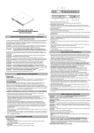
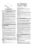
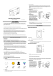
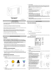
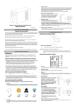
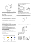
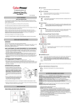
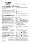
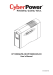
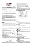
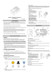
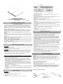
Office Rack Mount UPS
OR1000ELCDRM1U/OR1500ELCDRM1U
User’s Manual
K01-0000058-00
IMPORTANT SAFETY INSTRUCTIONS
(SAVE THESE INSTRUCTIONS)
This manual contains important instructions that should be followed during installation and maintenance
of the UPS and batteries. Please read and follow all instructions carefully during installation and
operation of the unit. Read this manual thoroughly before attempting to unpack, install, or operate.
CAUTION! The UPS must be connected to a grounded AC power outlet with fuse or circuit breaker
protection. DO NOT plug the UPS into an outlet that is not grounded. If you need to de-energize this
equipment, turn off and unplug the UPS.
CAUTION! DO NOT USE FOR MEDICAL OR LIFE SUPPORT EQUIPMENT! CyberPower Systems
does not sell products for life support or medical applications. DO NOT use in any circumstance that
would affect the operation or safety of any life support equipment, with any medical applications, or
patient care.
CAUTION! The battery can energize hazardous live parts inside even when the AC input power is
disconnected.
CAUTION! To prevent the risk of fire or electric shock, install in a temperature and humidity controlled
indoor area, free of conductive contaminants. (Please see specifications for acceptable temperature and
humidity range).
CAUTION! To reduce the risk of electric shock, do not remove the cover, except to service the battery.
There are no user serviceable parts inside, except for the battery.
CAUTION! To avoid electrical shock, turn off the unit and unplug it from the AC power source before
servicing the battery or installing a computer component.
CAUTION! DO NOT USE WITH OR NEAR AQUARIUMS! To reduce the risk of fire, do not use with
or near aquariums. Condensation from the aquarium can come in contact with metal electrical contacts
and cause the machine to short out.
CAUTION! DO NOT USE WITH LASER PRINTERS! The power demands of laser printers are too
large for a UPS.
INSTALLING YOUR UPS SYSTEM
UNPACKING
The box should contain the following:
®
(1) PowerPanel Business Edition software CD*1;(2) USB cable *1; (3) Phone line *1; (4) user manual*1;
(5) UPS unit*1(6)Green Power Technology description*1
OVERVIEW
The OR1000ELCDRM1U/OR1500ELCDRM1U provides automatic voltage regulation for inconsistent
utility power. The OR1000ELCDRM1U/OR1500ELCDRM1U features 1030 Joules of surge protection,
and provides battery backup during power outages. The OR1000LCDRM1U/OR1500LCDRM1U
ensures consistent power to your computer system and its included software will automatically save
your open files and shutdown your computer system during a utility power loss.
HOW TO DETERMINE THE POWER REQUIREMENTS OF YOUR EQUIPMENT
1. Make sure that the total Volt-Amp (VA) requirements of your computer, monitor, and peripheral
equipment does not exceed 1000 VA/ 1500VA.
2. Ensure that the equipment plugged into the four battery power-supplied/surge outlets does not
exceed the UPS unit's rated capacity (1000VA/600W for OR1000ELCDRM1U, 1500VA//900W for
OR1500ELCDRM1U). If the rated unit capacities are exceeded, an overload condition may occur
and cause the UPS unit to shut down and the circuit breaker to trip.
3. If the power requirements of your equipment are listed in units other than Volt-Amps (VA), convert
Watts (W) or Amps (A) into VA by performing the calculations below. Note: The equation listed
below only calculates the maximum amount of VA that the equipment can use, not what is typically
used by the equipment at given time. Users should expect usage requirements to be approximately
60% of the maximum power requirements:
Watts (W) x 1.67 =
VA or Amps (A) x 230 = VA
Add the totals up for all pieces of equipment and multiply this total by 0.6 to calculate the approximate
requirements.
There are many factors that can affect the amount of power that your computer system will require.
The total load that you will be placing on the battery-powered outlets should not exceed 80% of the
unit's capacity.
4. LCD function selected switch
The switch can be used to select the LCD display contents Including input/output voltage and
estimated run time, etc.
5. Battery, Surge and AVR Outlets
Provides four battery power, surge protected and AVR outlets for connected equipment and ensures
temporary uninterrupted operation of your equipment during a power failure.
6. Surge Outlets
Provides two surge protected outlets for connected equipment.
7. Communication Protection Ports RJ11/RJ45
Communication protection ports will protect any standard modem, fax, telephone line, or network
cable .
8. USB Port to PC
This port allows connection and communication from the USB port on the computer to the UPS unit.
®
The UPS communicates its status to the PowerPanel Business Edition software. This interface is
also compatible with the UPS application provided by Windows Vista and Mac OS X.
9. Serial Port to PC
This port allows connection and communicates from the DB-9 serial on the computer to the UPS unit..
10. Circuit Breaker
Located on the side of the UPS, the circuit breaker serves to provide overload and fault protection.
Under normal operating conditions, the circuit breaker is depressed.
11. AC Input
Connect the AC Power cord to a properly wired and grounded outlet.
12. Expansion Port
Allow users to add the optional SNMP card.
Hardware Installation Guide
1. Your new UPS may be used immediately upon receipt. However, recharging the battery for at least
four hours is recommended to ensure that the battery's maximum charge capacity is achieved.
Charge loss may occur during shipping and storage. To recharge the battery, simply leave the unit
plugged into an AC outlet. The unit will charge in both the on and off position.
2. If you will use the software, connect the USB cable to the USB port on the UPS.
3. With the UPS unit off and unplugged, connect the computer, monitor, and any externally powered
data storage device (Zip drive, Jazz drive, Tape drive, etc. into the battery power supplied outlets.
DO NOT plug a laser printer, copier, space heater, vacuum, paper shredder or other large
electrical device into the UPS. The power demands of these devices will overload and
possibly damage the unit.
4. To protect a fax, telephone, modem line or network cable, connect a telephone cable or network cable
from the wall jack outlet to the IN jack of the UPS. Then connect a telephone cable or network cable
from the OUT jack on the UPS to the modem, computer, telephone, fax machine, or network device.
5. Plug the UPS into a 2 pole, 3 wire grounded receptacle (wall outlet). Make sure the wall branch
outlet is protected by a fuse or circuit breaker and does not service equipment with large electrical
demands (e.g. air conditioner, refrigerator, copier, etc. Avoid using extension cords. If used, the
extension cord must be grounded and rated for 15 amps.
6. Depress the power switch to turn the unit on. The power on indicator light will illuminate and the unit
will "beep" once.
7. If an overload is detected, an audible alarm will sound and the unit will emit one long beep. To
correct this, turn the UPS off and unplug at least one piece of equipment from the battery power
supplied outlets. Wait 10 seconds. Make sure the circuit breaker is depressed and then turn the
UPS on.
8. Your UPS is equipped with an auto-charge feature. When the UPS is plugged into an AC outlet, the
battery will automatically recharge.
9. To maintain optimal battery charge, leave the UPS plugged into an AC outlet at all times.
10. To store your UPS for an extended period, cover it and store with the battery fully charged.
Recharge the battery every three months to ensure battery life.
BATTERY REPLACEMENT
CAUTION! Read and follow the IMPORTANT SAFETY INSTRUCTIONS before servicing the battery.
Service the battery under the supervision of personnel knowledgeable of batteries and their
precautions.
CAUTION! Use only the specified type of battery. See your dealer for replacement batteries.
CAUTION! The battery may present the risk of electrical shock. Do not dispose of batteries in a fire,
as they may explode. Follow all local ordinances regarding proper disposal of batteries.
CAUTION! Do not open or mutilate the batteries. Released electrolyte is harmful to the skin and eyes
and may be toxic.
CAUTION! A battery can present a high risk of short circuit current and electrical shock. Take the
following precautions before replacing the battery:
1. Remove all watches, rings or other metal objects.
2. Only use tools with insulated handles.
3. DO NOT lay tools or other metal parts on top of battery or any battery terminals.
4. Wear rubber gloves and boots.
5. Determine if the battery is inadvertently grounded. If inadvertently grounded, remove source of
ground. CONTACT WITH A GROUNDED BATTERY CAN RESULT IN ELECTRICAL SHOCK! The
likelihood of such shock will be reduced if such grounds are removed during installation and
maintenance (applicable to a UPS and a remote battery supply not having a grounded circuit)
BATTERY REPLACEMENT PROCEDURE:
BASIC OPERATION
DESCRIPTION
1. LCD module display
LCD shows all the UPS information with icons and messages.
2. Power on LED
The power on LED lights up when the UPS is ON.
3. Power Switch
Master on/off switch for equipment connected to the battery power supplied outlets.
1. Remove the right-side of the
faceplate.
2. Remove the three retaining
screws on the cable protection
cover then remove the
cover.faceplate.
3. Disconnect the black and red
TECHNICAL SPECIFICATIONS
5. Replace the new battery pack. Assemble
the screws, cover, cable and front panel in
the reverse sequence of above steps.
Recharge the unit for 4-8 hours to ensure
the UPS performs expected runtime
4. Remove the retaining screw of
the cable connectors.
DEFINITIONS FOR ILLUMINATED LCD INDICATORS
Line mode
Select SW
UPS Status Display
Capacity
Press
Digital Value Display
Display
Load
Battery
Input
Output
Run
% of
% of
Cap.
Cap.
Voltage
Voltage
Time
Load
Batt.
Initial
V
X
--
X
V
X
1st
V
X
--
X
V
X
V
2nd
V
X
--
X
V
X
3rd
V
X
--
X
X
V
4th
V
X
--
X
V
X
5th(Return)
V
X
--
X
V
X
Press >3sec
(Sound
Disable)
V
X
V
X
--
--
--
--
--
--
--
Press >3sec
V
X
X
X
--
--
--
--
--
--
--
V
V
V
V
V
again(Sound
Enable)
(Overload)
V
"V" : Illuminated,
X
--
V
--
--
--
--
--
--
--
"X" : Not Illuminated, "--" : Either
Battery mode
Select SW
UPS Status Display
Capacity
Press
OR1000ELCDRM1U
1000VA/600W
OR1500ELCDRM1U
1500VA/900W
160VAC~270VAC
50/60Hz (Auto Sensing)
Boost Only
230Vac +/-10%
50/60Hz +/-1%
4ms Typical
On Utility: Circuit Breaker, On Battery: Internal Current Limiting
Yes
RJ11/RJ45 ( One In/ One Out )
+32°F to 104°F ( 0°C to 40°C )
IEC320 C 13 x 6 ( Backup x 4 )
1U Rack 43.3 x 38.9 x 4.4
1U Rack 43.3 x 48.5 x 4.4
16.1
19.4
6V / 7Ah x4
6V / 9Ah x4
8 hours
1A
Yes
Power On, Wiring Fault, LCD Display
On Battery, Low Battery, Overload
Windows 2000/NT/XP/Vista,Mac OSX,Linux
Yes
Yes
Yes
Yes
Yes
Optional
Digital Value Display
Display
Load
Battery
Input
Output
Run
% of
% of
Cap.
Cap.
Voltage
Voltage
Time
Load
Batt.
Initial
X
V
--
X
V
X
1st
X
V
--
X
V
X
2nd
X
V
--
X
V
X
3rd
X
V
--
X
X
V
4th
X
V
--
X
V
X
5th(Return)
X
V
--
X
V
X
Press >3sec
(Sound
Disable)
X
V
V
X
--
--
Press >3sec
X
CYBERPOWER GREENPOWER UPS TECHNOLOGY
V
Our new UPS circuit is designed to save energy operating in GreenPower
V
Bypass Mode.
V
V
A traditional UPS circuit with AVR provides normal output voltage through the
V
Relay and AVR transformer. The current travels first through the transformer
V
--
--
--
--
--
conducting energy and generating heat. This heat creates energy dissipation
resulting in a "Power Loss" or consumption of utility power and money.
V
X
X
--
--
--
--
--
--
--
again(Sound
CyberPower's GreenPower Circuit Design is a solution to this "Power Loss." When the Utility Power is
operating normally, our Green Power UPS works in Bypass Mode. Our GreenPower design conducts
Enable)
(Overload)
Model
Capacity (VA)
Input
Input Voltage Range
Frequency Range
AVR Function
Output
On Battery Output
Voltage
On Battery Output
Frequency
Transfer Time
Overload Protection
Surge Protection
Lightning / Surge
Protection
Network/ Phone/ Fax/
Modem Protection
Operating Temperature
Physical
Total # of UPS outlets
Maximum
Dimensions(cm)
Weight (kg)
Battery
Sealed Maintenance
Free Lead Acid Battery
Typical Recharge Time
Charging Current(Max.)
User Replaceable
Status Indicators
Indicators
Audible Alarms
Communication
®
PowerPanel Business
Edition Software
Management
Self -Test
Auto-Charger
Auto-Restart
USB interface
Dry contact Closure
SNMP/HTTP
Networking
power only through the Relay and still provides normal output voltage. Bypassing the transformer
X
"V" : Illuminated,
V
--
V
--
--
--
--
--
--
"X" : Not Illuminated, "--" : Either
--
reduces power consumption thereby conserving energy and saving money.
When the utility power is
abnormal the UPS will operate under Battery or AVR Mode. Under this condition Green Power UPS and
a traditional UPS would operate about the same.
On average utility power operates 88% of the time and the CyberPower GreenPower Technology will
TROUBLE SHOOTING
work in its money/energy saving Bypass Mode.
Problem
Full-time surge
protection outlets
stop providing
power to
equipment.
The UPS does
not provide
expected
runtime.
The UPS will not
turn on.
PowerPanel
®
Possible Cause
Circuit breaker has tripped
due to an overload.
For more information, visit eu.cyberpowersystems.com or contact
CyberPower Systems B.V.
Flight Forum 3545 5657DW Eindhoven The Netherlands
Battery not fully charged.
Battery is slightly worn out.
Recharge the battery by leaving the UPS
plugged in.
Tel: +31 40 2348170, E-MAIL: [email protected]
Contact CyberPower Systems about
replacement batteries at
[email protected]
Tel: +1 952 4039500, Fax: +1 952 4030009, E-MAIL: [email protected]
The on/off switch is
designed to prevent
damage by rapidly turning it
off and on.
Turn the UPS off. Wait 10 seconds and
then turn the UPS on.
The battery is worn out.
Contact CyberPower Systems about
replacement batteries at
[email protected]
Mechanical problem.
Contact CyberPower Systems at
[email protected]
The USB cable is not
connected.
Business Edition
is inactive.
Solution
Turn the UPS off and unplug at least one
piece of equipment. Wait 10 seconds,
reset the circuit breaker by depressing the
button, and then turn the UPS on.
The unit is not providing
battery power.
Connect the USB cable to the UPS unit
and an open USB port on the back of the
computer.
Shutdown your computer and turn the
UPS off. Wait 10 seconds and turn the
UPS on. This should reset the unit.
Additional troubleshooting information can be found at eu.cyberpowersystems.com
CyberPower Systems Inc. (USA) 4241 12th Avenue East, Suite 400, Shakopee, MN 55379, U.S.A.
Entire contents copyright ©2004 CyberPower Systems B.V., All rights reserved. Reproduction in whole
or in part without permission is prohibited. PowerPanel® and PowerPanel® Plus are trademarks of
CyberPower Systems (USA) Inc.