1
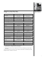
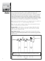
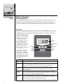
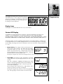
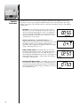
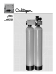
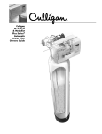
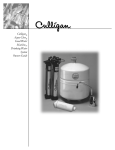
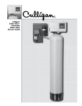
Culligan® Iron-Cleer® Plus Automatic Water Filter Owners Guide Thank You And Welcome To Your New World Of Better Living With Culligan Water. This system and its installation must comply with state and local regulations. The System is ONLY to be supplied with cold water. The Culligan® Iron Cleer® water filter has been tested and certified by WQA against WQA S-200 for the effective reduction of iron up to 1,400 gallons for 10” units and 2,000 gallons for 12” units. Do not use with water that is microbiologically unsafe or of unknown quality without adequate disinfection before or after the system. For installations in Massachusetts, the Massachusetts Plumbing Code 248 CMR shall be adhered to. Consult your licensed plumber for installation of the system. This system and its installation must comply with state and local regulations. The use of saddle valves is not permitted. If this is your first experience having filtered, conditioned water in your home, you’ll be amazed at the marvelous difference it makes. We promise that you’ll never want to be without it again. Congratulations, too, on selecting one of the “first family” of water filters in the prestigious Culligan Iron-Cleer. With Culligan’s many years of knowledge and experience in water treatment, you can be confident that the model you selected has been designed and engineered to provide years of service with a minimum of care and attention. Products manufactured and marketed by Culligan International Company (Culligan) and its affiliates are protected by patents issued or pending in the United States and other countries. Culligan reserves the right to change the specifications referred to in this literature at any time, without prior notice. Culligan, Culligan Iron-Cleer, Cullar, Filtr-Cleer, Cullneu, Accusoft, Culligan Man and www.culligan. com are trademarks of Culligan International Company or its affiliates. Attention Culligan Customer: The installation, service and maintenance of this equipment should be rendered by a qualified and trained service technician. Your local independently operated Culligan dealer employs trained service and maintenance personnel who are experienced in the installation, function and repair of Culligan equipment. This publication is written specifically for these individuals and is intended for their use. We encourage Culligan users to learn about Culligan products, but we believe that product knowledge is best obtained by consulting with your Culligan dealer. Untrained individuals who use this manual assume the risk of any resulting property damage or personal injury. ii Specifications . . . . . . . . . . . . . . . . . . . . . . . . . . . . . . . . . . . . . . . . . . . . . . . . . 1 Introduction . . . . . . . . . . . . . . . . . . . . . . . . . . . . . . . . . . . . . . . . . . . . . . . . . . 2 Table of Contents Operating Conditions . . . . . . . . . . . . . . . . . . . . . . . . . . . . . . . . . . . . . . . . . . . 4 Familiarization . . . . . . . . . . . . . . . . . . . . . . . . . . . . . . . . . . . . . . . . . . . . . . . . 5 Programming . . . . . . . . . . . . . . . . . . . . . . . . . . . . . . . . . . . . . . . . . . . . . . . . . 7 Statistic Functions . . . . . . . . . . . . . . . . . . . . . . . . . . . . . . . . . . . . . . . . . . . . . 10 When and How to Bypass your Water Filter . . . . . . . . . . . . . . . . . . . . . . . . . . 11 Things to Check Before You Call for Service . . . . . . . . . . . . . . . . . . . . . . . . . . 13 Preventative Maintenance . . . . . . . . . . . . . . . . . . . . . . . . . . . . . . . . . . . . . . . 14 Troubleshooting Guide . . . . . . . . . . . . . . . . . . . . . . . . . . . . . . . . . . . . . . . . . . 15 Performance Data Sheet . . . . . . . . . . . . . . . . . . . . . . . . . . . . . . . . . . . . . . . . . 18 Records and Data . . . . . . . . . . . . . . . . . . . . . . . . . . . . . . . . . . . . . . . . . . . . . 19 Warranty . . . . . . . . . . . . . . . . . . . . . . . . . . . . . . . . . . . . . . . . . . . . . . . . . . . 20 iii This page intentionally left blank. iv Culligan® Iron Cleer® Plus Filters Specifications 10” Iron Cleer 12” Iron Cleer 1” 5-cycle reinforced thermoplastic 1” 5-cycle reinforced thermoplastic Electro-mechanical Electro-mechanical 67” 65” 2 ea. 10” x 54” tanks 2 ea. 12” x 52” tanks 1.0 cu. ft. birm 1.5 cu. ft. birm 35 lbs. 35 lbs. 25 lbs. 25 lbs. 1400 gallons 2000 gallons 21” 18” Max. Clear Water (Soluble) Iron 10 ppm 10 ppm Max. Hydrogen Sulfide 5.0 ppm 5.0 ppm Minimum Alkalinity 100 ppm 100 ppm pH 7.0 - 8.5 7.0 - 8.5 Control Valve Timer Overall Conditioner Height Media Tank Dimensions (D x H) Filter Media Type Underbedding G-50 Cullsan U Capacity 1 Freeboard 2 Service Flow @ Pressure Drop (Clean Bed) Normal 5 gpm @ 9 psi 7 gpm @ 10 psi 6 gpm @ 11 psi 9 gpm @ 14 psi 20-60 psi 20-60 psi Operating Temperature 33-120° F (1-48° C) 33-120° F (1-48° C) Electrical Requirements 120 Volts/60 Hz 120 Volts/60 Hz Power Consumption, Continuous/ Maximum 3 watts/203 watts 3 watts/203 watts 10 gpm (5.5 gpm min. req.) 10 gpm (8.0 gpm min. req.) Backwash 5 - 20 minutes 5 - 20 minutes Fast Rinse 5 - 20 minutes 5 - 20 minutes Maximum 3 Operating Pressure Drain Flow, Maximum Regeneration Time 1 Capacity based on 4 gpm and 10 mg/L of dissolved iron. 2 Measured from top of media bed to top of inlet fitting. 3 Max flow rates & pressure drop characteristics have not been validated by the Water Quality Association. The max specified flow rate at which the system will deliver treated water as validated by the Water Quality Association is defined as service flow. Introduction Operation Step 1. Aeration Operation Service Cycle In the service cycle, raw water enters the inlet port of the aeration tank and is directed through the inlet diffuser. The oxidation process begins when the water passes through the inlet diffuser and cascades through a head of air. This air/ water contact oxidizes the iron, manganese, hydrogen sulfide in the water. The water is directed toward the bottom of the tank and travels through the pickup tube. It then passes through the outlet of the aeration tank to the inlet of the filter tank. Filter Tank Operation Service Cycle Raw water enters the filter tank through the inlet port of the filter control valve. Upon system demand for filtered water, water is directed to the top of the tank and flows downward through the multimedia filter bed toward the lower distributor. Oxidized iron particles are trapped by the filter bed as the water passes through. Filtered water enters the lower distributor and travels up the distributor tube to the outlet port on the filter valve. Step 2. Aeration Operation Air Recharge Cycle When energized, the air pump sends air through the solenoid valve into one end of the shuttle valve. Once air pressure in the shuttle valve is greater than the water supply pressure at the other end of the shuttle valve, the piston shifts to the open position. In the open position, the bleed-off port discharges excess water and old air to the drain port through a flow restrictor. Simultaneously, the air inlet port opens to provide a direct connection between the air pump and the top of the aeration tank. The air pump runs for a preset period of time recharging the head of air in the aeration tank. Air Recharge Shut Off The timer turns power off to the air pump and the solenoid valve at the end of the recharge cycle. The solenoid valve then closes the port between the air pump and the shuttle valve. The port between the shuttle valve and the atmosphere opens and releases air pressure. This allows water pressure to shift the piston to the closed position. With the piston in the closed position, the air recharge inlet port is closed and direct communication between the bleed off tube and the drain port is also closed. Timer Operation A timer controls the air recharge cycle and how frequently it occurs. The timer simultaneously energizes the air pump and the solenoid valve. After a preset amount of time, the timer shuts off the air pump and de-energizes the solenoid valve. Solenoid Valve Operation The solenoid valve is a three-way valve having ports that connect to the air pump, shuttle valve and the atmosphere. In the service cycle, the solenoid valve is de-energized and closes the port to the air pump, providing a positive shut-off to the pump. This prevents water from backing up into the air pump and damaging the pump. In the air recharge cycle, the solenoid valve closes the port to the atmosphere and opens the port from the air pump. Shuttle Valve Operation In the service position, water pressure holds the shuttle valve piston in the closed position, trapping the airhead in the aeration tank and closes the air recharge inlet port and drain port. During air recharge cycle, air pressure is greater than the water pressure and forces the shuttle valve piston in the open piston. The shuttle valve has an internal pressure relief valve that will relieve pressure (greater than 100 psi) that may build up in the aeration tank. This precautionary function protects components from failure due to excessive pressure. Introduction (cont.) Step 3. Filter Tank Operation - Backwash Cycle Reversing the flow of water through the filter bed and backwashing dirty water to the drain cleans the filter bed. Raw water enters the filter control valve through the inlet port and is directed down the distributor tube and out the lower distributor at the bottom of the tank, flowing upward through the multimedia filter bed toward the top of the tank into the control valve. Water is then directed through a specific flow restrictor and out the drain port to be discharged to drain. Step 4. Filter Tank Operation - Rinse Cycle The rinse cycle packs the clean filter bed. Raw water enters the control valve through the inlet port and is directed downward through the filter bed into the bottom distributor, up the distributor tube into the control valve. Water is then directed through a specific flow restrictor and out the drain port to be discharged to drain. Operation Of Aeration Pump The Iron-Cleer® system introduces air into the aeration tank and bleeds off the old head of air automatically. The exchange of the air into the aeration tank is controlled independently of the recharge frequency of the filter media tank, allowing the air to be exchanged on a more frequent basis. During an air exchange cycle, the air compressor pumps fresh air into the aeration tank and the air eliminator solenoid exhausts the old air. Advantages Over Other Systems 1. No chemicals or salt. 2. No air injectors, venturis, or micronizers. 3. No floats to regulate air volume in aeration tank which “foul” from iron. 4. Two-tank system consisting of a pressurized aeration tank and multi-media depth filter. 5. 110V aeration pump to recharge aeration tank. 6. Can be used on shared wells, municipal water supplies or with buried pressure tanks without additional equipment. 7. Better filtration results. Operating Conditions The concentration limits listed below reflect the maximum individual limit that each contaminant was tested for separately without any interference of other contaminants in the influent water. In reality, however, we know that these contaminants may be present in combination which may limit the filter’s ability to remove these contaminants in higher concentrations. In some cases, individual sellers of this equipment have had success removing higher concentrations of contaminants - iron, for example - above the limitations we have listed. If you are considering the installation of this system for the reduction/removal of iron, manganese and/or hydrogen sulfide beyond the printed operating conditions below, we recommend that you consult the manufacturer for proper application. Installation of this system under these circumstances may void part(s) and/or all of the system warranty. pH — The pH level of the influent water must be 6.5 - 8.5. A pH level of 7.0 - 8.5 is optimal for iron reduction and a pH level of 6.5 - 7.5 is optimal for hydrogen sulfide reduction. Iron — This system is rated for a maximum of 10 ppm of ferrous (clear water) and/or ferric (red water) iron. Consult the factory if iron bacteria is present. Hydrogen Sulfide — Often referred to as rotten egg odor, hydrogen sulfide will be reduced significantly on water supplies containing less than 5 ppm. Consult the manufacturer if hydrogen sulfide concentrations is greater than 5 ppm. Organic Matter (Tannins) — The presence of organic matter such as tannins will prevent the oxidation process of converting the dissolved element, such as iron or manganese, to a non-soluble precipitate or solid substance, allowing it to be filtered out. The Iron-Cleer® is not designed to remove organic bound iron. Filtered Non-Softened Water Unfiltered Water To Outside Hosebibs Raw Water In Softened & Filtered Water Iron-Cleer Water Softener Iron-Cleer Filter Tank Iron-Cleer Aeration Tank Note: Waste connections or drain outlets shall be designed and constructed to provide for connection to the sanitary waste system through an air gap of 2 pipe diameters or 25.4 mm (1 in.) whichever is larger. Figure 1 Power Loss Familiarization The AccuSoft circuit board is equipped with a Hi-Cap Capacitor and EEPROM memory chip. The capacitor is capable of maintaining the time, for at least two days, in the event of a power outage. The EEPROM ensures that the individual programming parameters of your filter are not lost. ® If the power outage lasts long enough to drain the Hi-Cap Capacitor, the control will flash “12:00 PM” when power is returned to the control. The unit will continue to keep time from the moment power is restored, and will initiate a full regeneration at the preset regeneration time. The time of day will need to be reset in order to return the regeneration to its preset time. If you live in an area where power outages occur with a regular frequency, a battery backup option is available for ensuring that the time of day is properly maintained. Contact your Culligan Dealer for more information. Regeneration To initiate a regeneration at the preset time, press the “REGEN” button. The “REG” light will light. To initiate an immediate regeneration, press and hold the “REGEN” button for at least three seconds. The “REG” will light and blink. An immediate regeneration will also occur if a power outage has lasted for more than three hours and the Immediate Regeneration option is chosen. Ask your Culligan Dealer about this feature. A regeneration at the Time of Regeneration will occur if so signaled by the Soft-Minder meter. The “REG” enunciator on the display will also be lit. Service Culligan’s Iron-Cleer® water filter is equipped with a self diagnostic program to insure optimal operation of your water filter. Should service become necessary, a phone icon will appear in the display. If this condition occurs, call your local Culligan Dealer for assistance. The phone icon and error code will be the only items displayed when service is required on the control. Familiarization (cont.) Modes of Operation Manual Regeneration Pressing and holding the regen button for 3 seconds will initiate an immediate regeneration. The beeper is to give one beep at the start of manual regeneration (when the motor starts to turn). In delay mode, pressing and releasing the regen button will light the regen icon for regeneration to occur at the set delay time. Pressing and releasing the regen button again will turn off the regen icon. Power Loss The AccuSoft® circuit board is equipped with a Hi-Cap Capacitor and EEPROM memory chip. The capacitor is capable of maintaining the time, for at least one day, in the event of a power outage. The EEPROM ensures that the individual programming parameters of your softener are not lost. If the power outage lasts long enough to drain the Hi-Cap Capacitor, the control will flash “12:00 PM” when power is returned to the control. The unit will continue to keep time from the moment power is restored, and will initiate a full regeneration at the preset regeneration time. The time of day will need to be reset in order to return the regeneration to its preset time. If you live in an area where power outages occur with a regular frequency, a battery backup option is available for ensuring that the time of day is properly maintained. Contact your Culligan Dealer for more information. Display Program Key Toggle Down Program Regen Information Press Regen once to begin regeneration tonight. Or hold for immediate regeneration. Setting Time Of Day 1. Press Program until 'tod' is displayed. 2. Use arrow keys to adjust minutes. 3. Press Regen once then adjust hours. 4. Continue to press Program to exit menu & save. Regeneration Key Information Key Toggle Up Display Back-lit LCD display. Program Key Depress to enter and move through the programming steps. Regeneration Key Press and hold the key for three (3) seconds to initiate an immediate regeneration. Information Key Each time depressed, the Information key will display statistical information such a flow rate, time of day. Use with the Toggle Down key to display other statistical information. Toggle Down Key In the programming mode this key will move the user through the programming function in a descending mode. If depressed for greater than three seconds, the rate at which the display scrolls through data will increase. Toggle Up Key In the programming mode this key will move the user through the programming function in an ascending mode. If depressed for greater than three seconds, the rate at which the display scrolls through the data will increase. When pressed during programming the time of day, this key will allow the user to toggle between the hours and minutes setting of timing program segments. This key will also allow the user to manually step through the cycles of regeneration. Programming The Culligan® AccuSoft® Plus circuit board controls all of the filter functions. These settings are programmed at the time of installation. The following is a list of all the microprocessor functions, in the event that any of the settings need to be adjusted. % Display Icons The display is to be backlit and have the icons as shown below. Custom LCD Display Six standard 12-segment alpha-numeric characters, a decimal separating the first and second character, a colon separating the second and third character positions, AM, PM, REGEN, EFFICIENCY MODE, TODAY’S, AVG DAILY, WATER USAGE, SOFTWATER, REMAINING, %, MINS, BACKWASH, BRINE RINSE, FAST RINSE, REFILL, GALLONS, LITERS, FLOW RATE, GPM, LPM Icons A further description of each programming setting and the corresponding display is outlined below. For a display that has an icon that is displayed solid for the 2 second time period prior to bringing up the settings, the settings menu can be reached prior to the two second time out by pressing the “+” or “-” key. • Beeper Setting - This setting is used to turn the beeper on or off for each key press actuation. The display will show “bEEP X” where X is either “Y” or “N”. The “Y” or “N” will be toggled with the “Up” and “Down” keys. Setting the Beep option to “N” will only disable the beeper for key press actuation. The beeper will still be active for error and alarm codes. Pressing the “Program” key will save the setting and move to the next programming step. • Time of Day - This setting is used to program the current time of day. When in this step the display will first show “tod” for two seconds. After “tod” is displayed, “12:00 PM” will display (or the current set time if already programmed) and the minutes will flash. The minutes are adjusted with the “Up” or “Down” key until the correct value is displayed. Press the “Regen” key to flash the hours. Adjust with the “Up” or “Down” key until the correct time is displayed. Pressing the “Program” key will move to the next programming step. Pressing “Regen” will move back to the minutes adjust. Minutes Flashing Hours Flashing Programming (cont.) • Time of Regeneration - This setting is used to program the time at which a regeneration is to occur in the delay mode, or in immediate mode with time clock backup on. The display will first show “tor” for two seconds. After “tor” is shown the display will then show the default of 2:00 AM (or the current programmed time of regeneration if already set). The time can be adjusted in 30 minute increments by pressing the “Up” or “Down” keys. Time Flashing Pressing the “Program” key will save the setting and move to the next programming step. • Cycle 1 Time (Backwash) – This setting is used to program the backwash cycle. The time of the cycle is kept in minutes. The display will show the “Backwash” and “Mins” icons and the cycle time in the right most digits. Adjust the value with the “Up” or “Down“ keys. Pressing the “Program” key will save the setting and move to the next programming step. • Cycle 2 Time (Pause) – This setting is used to set the time in minutes for cycle 2. This cycle is usually brine draw / slow rinse for softeners and a settling time for filters. The display will show the “BRINE RINSE” and “MINS” icons and the cycle time in the right most digits. Adjust the value with the “Up” or “Down“ keys. Pressing the “Program” key will save the setting and move to the next programming step. • Cycle 3 Time (Fast Rinse) – This setting is used to set the time in minutes for cycle 3. This cycle is usually fast rinse for softeners and filters. For softener applications it may include the refill operation. The display will show the “FAST RINSE”, “/”,“REFILL” and “MINS” icons for 4-cycle valves or “FAST RINSE” and “MINS” icons for 5-cycle valves and filters with the cycle time in the right most digits. Adjust the value with the “Up” or “Down“ keys. Pressing the “Program” key will save the setting and move to the next programming step. • Regeneration Interval - This setting is used to set the days between regeneration in time clock mode. It is also active in meter mode if the time clock backup DIP switch # 10 is set to on. The display will show “REGEN” icon and “dAYS” as well as the numbers to change. Adjust the value with the “Up” or “Down” keys. Pressing the “Program” key will save the setting and move to the next programming step. • Filter Media Life (Change Media) - This setting is used in Filter Mode ONLY with flow meter attached. It enables or disables an alarm code (“CHANGE MEDIA”) that indicates the end of life for the filter media. The display will show “LIFE” in the left most characters and toggle between “Y” and “N” in the right most character with the “+” and “-“ keys. If “NO” is selected, the alarm is disabled and the ‘Total Capacity’ setting will be treated as it is in Flow Meter Mode (softener). If “YES” is selected, the alarm is enabled and will sound when the ‘Total Flow/Life of Unit’ statistic = ‘Total Capacity’ setpoint, indicating that it is time to change the filter media. Pressing “Program” key will save and advance to the next step. • Total Capacity Set Point (Max Capacity) - This setting is used to program a value that corresponds to the maximum capacity that can be expected from a unit before it is completely exhausted (no reserve). This setting will only appear if a flow meter is connected to the circuit board. The display will show the “REGEN” icon and “MAXCAP” for two seconds and then display the “REGEN” and “GALLONS” or “LITERS” icons (depending on DIPswitch #7 setting) and the setting numbers to adjust. Adjust the value with the “Up” or “Down” keys. 9999 99 When the capacity used equals this total capacity setting with the “Life” feature off, the control will regenerate either immediately or at the time of regen based on the “hidden programming menu” setting. With the “Life” feature on, the control will use this setting to trigger the “Change Media” alarm. Pressing the “Program” key will save the setting and move to the next programming step. • Batch Set Point - This setting is used to set the trip point for regeneration when in flow meter operation. It will only appear if a flow meter is connected. The programmed setting displays the actual set point to trigger regeneration. The display will show the “REGEN” icon and “bAtCH” for two seconds and then display the “REGEN” and “GALLONS” or “LITERS” icons (depending on dip#7 setting) and the setting numbers to adjust. Adjust the value with the “Up” or “Down” keys. Programming (cont.) Pressing the “Program” key will save the setting and move to the next programming step. OOO8 7O Statistic Functions The statistical functions are reached by pressing the “Information” key. Repetitive presses of the “Information” key will cycle through the standard statistics mode until cycled back to time of day display. Once either of the Information menus is entered the information shown for each display is outlined below: • Flow Rate - This display will only show if the flow meter is attached to the control. The display shall show the current flow rate of the water passing through the control. The display will show the “Flow Rate” and “GPM” icons and the current flow rate passing through the flow meter for as long as the “-” key or “Information” key is not pressed. • Capacity Remaining (%)(standard statistics) - This display will only show if the flow meter is attached to the control. The display shows the percent capacity remaining before regeneration will be triggered. The display will show the “Water Usage”, “Remaining” and “%” icons. • Today’s Water Usage - This display will only show if the flow meter is attached to the control. The display will show the accumulated flow of water for the current day. The value is to start totalizing at 12:00 AM and reset to 0 at 11:59:59 PM. The display will show the “Today’s”, “Water Usage” and “Gallons” icons and the total days flow. • Average Daily Water Usage - This display will only show if the flow meter is attached to the control. The display will show a running 7-day average of daily water usage. The display will show the “Avg Daily”, “Water Usage” and “Gallons” icons and the averaged flow value. 10 % Normally, all water except outside lines passes through the water conditioner. There are times when the water conditioner should be bypassed, using the Cul-Flo-Valv® Bypass, or a 3-way bypass valve. You should bypass: 1. If lines to outside faucets do not bypass the water conditioner, and you do not want to waste conditioned water on lawn sprinkling or other outside uses. When and How to Bypass Your Water Conditioner 2. If you are going away on vacation and want to save salt by not having the unit recharge while you’re away. Bypass Valve In the back of Culligan water conditioners is a push-button Cul-Flo-Valv® Bypass. To bypass unit, simply turn the blue knob clockwise. To return to soft water service, reverse the procedure - turn the blue knob counter-clockwise. Bypassed To BYPASS, turn the blue knob clockwise (see directional arrow on end of knob) until the knob stops as shown. DO NOT OVERTIGHTEN! About 1-1/4” A screwdriver shank may be used in the slot (arrow) as a lever for extra turning force if needed. Soft Water To return to SERVICE, turn the blue knob counter-clockwise (see directional arrow on end of knob) until the knob stops as shown. DO NOT OVERTIGHTEN! 11 When and How to Bypass Your Water Filter (cont.) Aeration Tank Bypass Valve Aeration Tank – Bypass Valve Operation Normal Operation “Treated” Water Exits Supply Water Enters Diagnostic Mode Supply Water Exits 12 Supply Water Enters Bypass Operation Supply Water Exits Supply Water Enters Shut-Off Mode No Water Exits Supply Water is Shut Off From The House and The Valve If you unexpectedly experience problem water, make these simple checks before calling your Culligan dealer. One of the following conditions may be the reason for your interruption of service. Important If any of the following conditions is found, the water filter should be manually recharged according to instructions on page 5 after you have corrected the problem. Things to Check Before You Call for Service Power Supply Check your power supply cord. Is it plugged fully into the electric outlet? Be certain that the outlet is not controlled by a wall switch which has been turned off. Reset conditioner to proper time of day and then plug in. Blown Fuse Check the house fuse or circuit breaker panel. Replace a blown-out fuse or reset an open circuit breaker. Power Failure Any interruption in your power supply or time changes - such as daylight savings - will disrupt your filter’s recharge schedule by causing the timer to run off-schedule. Reset timer to proper time of day. Bypass Valves Check to see if they are in the proper position. Cul-Flo-Valv® Bypass, if used, should be in the “Service” position. If hand valves are used, see that inlet and outlet valve are opened and that the bypass valve is closed. No Water If you aren’t getting any water flow at all, make sure your water supply is working. Open a tap ahead of the filter (outside tap) to see if you have any water pressure. If you have water pressure, check the bypass valve. If it is in the Service position, put it into the bypass and call your Culligan dealer for service. Increased Usage Guests, family additions, new water-using appliances, etc., all will result in more water usage and will require more capacity from your filter. You can reprogram your recharging schedule by following the directions on pages 7 – 9. Call your Culligan dealer for advice and save a service call. 13 Recommended Preventative Maintenance The Culligan Iron Cleer water filter has been designed to provide a good, consistent service life. Because of the nature of problem water, we recommend that the local Culligan dealer provide regular maintenance/service contracts for the proper operation of your systems. The water filter service begins with a multi point inspection of your water filter system in an effort to uncover any and all problems that may exist. Listed below is a recommended list of maintenance items to be inspected at a minimum of once a year (or more frequently depending on the raw water quality). Test Water Feed Product Hardness Iron Hydrogen Sulfide Chlorine TDS Other Comments: Bypass Valve Bypass in Service or Bypass? Condition of bypass valve Operation OK? Control Valve Condition of Seal Pack Condition of Solenoid Valve Condition of Motor: Condition of Flow Control Condition of Switches: Condition of Check Valve Condition of Shuttle Valve Output PSI Condition of Compressor Control settings Before After Check /reset Circuit Board Check time of regeneration Time delay relay setting “On Time” in seconds Time delay relay setting “Off Time” in minutes Backwash minutes Fast Rinse minutes Cycle control Test Cycle Backwash Fast rinse Media Tank Freeboard inches: 14 Media Condition OK? Complaint Problem Iron bleedthrough or staining. Cause A. Inadequate 1. Plugged drain line flow backwash of filter control 2. Insufficient water supply from well. 2. Faulty circuit board. 1. Call your Culligan dealer for service. 2. Check for minimum specified flow and pressure requirements of filter system. 3. Call your Culligan dealer for service. 4. Call your Culligan dealer for service. 1. Assure continuous electrical supply (check plug, breaker, fuses, etc.). 2. Replace circuit board. 3. Faulty drive motor. 3. Replace drive motor. 4. Circuit board set incorrectly. 4. Reset circuit board. 1. It is not uncommon for local water conditions to change. 1. Call your Culligan dealer for service. 3. Plugged aeration tank inlet diffuser or pick-up tube. 4. Media bed fouled. B. Fails to regenerate C. Water contaminant levels are greater than limits established by Culligan. D. Inadequate aeration 1. Interrupted electrical service. Troubleshooting Guide 1. Loss of air through inlet check 1. Call your Culligan dealer for valve. service. 2. Loss of air through air leak. 2. Call your Culligan dealer for service. 3. Faulty aeration pump. a. Electrical failure b. Pneumatic failure c. Damp environment E. Exceeding recommended filter system flow rate. F. Regeneration during service flow demand. G. Raw water bleeding through filter. Solution 4. Air loss through high demand. 1. Service flow rate demand is higher than filter system design flow rate. a. Assure permanent electrical service (check plug, breaker, fuses, terminal block on control valve, etc.). b. Call your Culligan dealer for service. c. Call your Culligan dealer for service. 4. Call your Culligan dealer for service. 1. Call your Culligan dealer for service. 1. Time of day set incorrectly. 1. Call your Culligan dealer for service. 1. Internal control valve leak. 1. Call your Culligan dealer for service. 15 Troubleshooting Guide (cont.) Complaint Problem Cause Solution Water leaking from relief valve. A. Dirt lodged under seat of valve. B. Faulty or defective relief valve A. This can be expected when water is aerated under pressure. 1. Pressure has exceeded rating on relief valve and caused valve to open 1. Call your Culligan dealer for service. 1. Call your Culligan dealer for service. 1. This natural phenomenon will typically dissipate to the atmosphere in a matter of seconds. If preferred, water can be drawn and stored in an open container prior to use (i.e. fill a pitcher and store in the refrigerator for cool, fresh drinking water). Water is effervescent 1. Water supply has been naturally aerated under well system pressure. As water is released to the atmosphere, air molecules separate from the water molecules. Loss of pressure A. See complaint #1, problem A & B Air spurting at outside or nonfiltered water fixtures. A. Inlet check valve not sealing. Air spurting from filtered water fixtures. A. Reduced pressure 1. Service flow demand is in distribution system. greater than water supply available from well pump system. 2. Water flow is restricted by supply piping and/or water treatment equipment. A. New filter 1. New filter media is backwashed during shipped in a dry condition first 24 hours after and must soak for 24 hours to installation. become fully saturated before a backwash cycle. B. Air passing 1. Excess air accumulated in through filter during aeration tank from aeration backwash. pump. 2. Excess air accumulated in filter system from water supply or well pump. Loss of media through drain line. Excessive noise during regeneration. 16 A. Howling or whistling noise during regeneration cycle. 1. Improper installation location. 2. Foreign material preventing check valve. 3. Worn or faulty check valve. 1. Inadequate drain line size. 2. Drain line is vibrating against other pipes, conduits, pipe hangers, heat ducts, floor joists,etc. 1. Call your Culligan dealer for service. 2. Call your Culligan dealer for service. 3. Call your Culligan dealer for service. 1. Repair or replace well pump system. 2. Call your Culligan dealer for service. 1. Clean drain line flow control, control valve body, seals, spacers and piston assemblies 1. Call your Culligan dealer for service. 2a. Repair well pump system. 2b. If the cause was due to temporary loss of water main pressure; the problem will most likely correct itself with the return of continuous pressure. 1. Call your Culligan dealer for service. 2. Call your Culligan dealer for service. Complaint Problem Cause Water is running to drain continuously. A. Control valve is 1. Electrical service stuck in regeneration to control(s) has been cycle. interrupted. 2. Faulty circuit board. 3. Faulty drive motor. Blue green staining. Compressor doesn’t run. Compressor run with excessive noise. Compressor runs continuously. A. Corrosive water condition in copper distribution piping system. Solution 1. Assure continuous electrical service is available. (check plug, breaker, fuse, etc.) 2. Replace circuit board.. 3. Call your Culligan dealer for service. 4. Call your Culligan dealer for service. 1. Call your Culligan dealer for service. 2. Call your Culligan dealer for service. 4. Foreign material lodged in piston. 1. Low pH condition of the raw water supply. 2. In rare occasions, highly aerated water in combination with a specific water supply can create a slightly corrosive condition. 1. Compressor unplugged. 1. Plug it in. 2. Relay settings incorrect. 2. Call your Culligan for service. 3. Bad relay. 3. Call your Culligan for service. 1. Dead head pressure is 65 1. Call your Culligan psi. for service. 2. Dead head pressure is 65 2. Call your Culligan psi. for service. 1. Incorrect relay settings 1. Call your Culligan for service. 2. Bad relay. 2. Call your Culligan for service. Troubleshooting Guide (cont.) dealer dealer dealer dealer dealer dealer 17 Performance Data Sheet Culligan® 10” and 12” Iron-Cleer® Water Filters Important Notice — Read this data sheet and compare the capabilities of the unit to your actual water treatment needs. Culligan recommends that you have your water supply tested to determine these needs before purchasing a water treatment unit. Culligan knows the more informed you are about your water treatment system, the more confident you will be about its performance. It’s because of this more than sixty five years of commitment to our customers that Culligan is providing this Performance Data Sheet to its customers. Manufacturer Culligan International Company 9399 West Higgins Road, Suite 1100, Rosemont, IL 60018 (847)430-2800 www.culligan.com Substance Reduction Model Substance USEPA SDWA* MCL (MG/L) Percent Average Influent Average Effluent Reduction Concentration Level Concentration Level 10” Iron-Cleer Iron 0.3 mg/L 99% 9.82 mg/L < 0.1 12” Iron-Cleer Iron 0.3 mg/L 99% 9.82 mg/L < 0.1 * United States Environmental Protection Agency Safe Drinking Water Act Testing Conditions Capacity: 1,400 gallons (10” Iron-Cleer) 2,000 gallons (12” Iron-Cleer) Pressure: Temperature: 63°F - 73°F Acidity: Flow Rate: 5 gpm (10” Iron-Cleer) 7 gpm (12” Iron-Cleer) pH: 8.0 60 psi Non-Corrosive Rated Pressure Drop @ 5 gpm: 9 psi (10” Iron-Cleer) Rated Pressure Drop @ 7 gpm: 10 psi (12” Iron-Cleer) Operating Conditions Water Pressure Limits: 20 - 60 psi Temperature Limits: 33 - 120°F Electrical Characteristics: 120V/60 Hz 3 Watts continuous Systems tested and certified by WQA against WQA S-200 for the effective reduction of iron. This system has been tested according to NSF/ANSI 42 for the reduction of iron. The concentration of iron in water entering the system was reduced to a concentration less than or equal to the permissible limit for water leaving the system as specified in NSF/ANSI 42. Testing was performed under laboratory conditions, actual results may vary. Performance Indicator: If water flow decreases or a noticeable odor returns, the filter should be reconditioned. If conditions do not improve, contact your local Culligan Man. He can determine if your filter requires servicing. Regeneration Frequency: Regeneration frequency will vary depending upon water conditions. Refer to your Installation and Operation Instructions, Parts List and Printed Warrantees for more specific product information. To avoid contamination from improper handling and installation, your system should only be installed and serviced by your Culligan Man. Performance may vary based on local water conditions. The substances reduced by this product are not necessarily in your water. Buyer Signature 18 Date Important Data on Your Water Filter It is advisable to have the salesperson or installer fill in the information below for your future reference. If this has not been done, please ask for it, as it is necessary if you contact your dealer. Records and Data Identification Model Name Catalog No. Control Model No. Control Serial No. Date of Installation Tank Serial No. Settings Time of Recharge: ______ a.m. ______ p.m. Regeneration Interval __________ days (Time clock models) Number of people in household Water Analysis Total Hardness _______ (gpg) Total Iron _______ (ppm) Hydrogen Sulfide____________ (ppm) Other 19 Culligan Limited Warranty Culligan® Iron-Cleer® Automatic Water Filters You have just purchased one of the finest water conditioners made. As an expression of our confidence in Culligan International Company products, your water conditioner is warranted to the original end-user, when installed in accordance with Culligan specifications, against defects in material and workmanship from the date of original installation, as follows: For a period of ONE YEAR The entire conditioner For a period of FIVE YEARS The AccuSoft® circuit board For a period of TEN YEARS The control valve body, excluding internal parts The conditioner tank If a part described above is found defective within the specified period, you should notify your inde pendently operated Culligan dealer and arrange a time during normal business hours for the dealer to inspect the water conditioner on your premises. Any part found defective within the terms of this warranty will be repaired or replaced by the dealer. You pay only freight from our factory and local dealer charges. We are not responsible for damage caused by accident, fire, flood, freezing, Act of God, misuse, misapplication, neglect, oxidizing agents (such as chlorine, ozone, chloramines and other related components), alteration, installation or operation contrary to our printed instructions, or by the use of accessories or components which do not meet Culligan specifications, is not covered by this warranty. Refer to the specifications section in the Installation and Operating manual for application parameters. Our product performance specifications are furnished with each water conditioning unit. To the extent permitted by law, culligan disclaims all implied warranties, including without limitation warranties of merchantability and fitness for particular purpose; to the extent required by law, any such implied warranties are limited in duration to the one-year period specified above for the entire conditioner. As a manufacturer, we do not know the characteristics of your water supply or the purpose for which you are purchasing a water conditioner. The quality of water supplies may vary seasonally or over a period of time, and your water usage rate may vary as well. Water characteristics can also differ considerably if your water conditioner is moved to a new location. For these reasons, we assume no liability for the determination of the proper equipment necessary to meet your requirements, and we do not authorize others to assume such obligations for us. Further, we assume no liability and extend no warranties, express or implied, for the use of this product with a non-potable water source. Our obligations under this warranty are limited to the repair or replacement of the failed parts of the water conditioner, and we assume no liability whatsoever for direct, indirect, incidental, consequential, special, general, or other damages. Some states do not allow the exclusion of implied warranties or limitations on how long an implied warranty lasts, so the above limitation may not apply to you. Similarly, some states do not allow the exclusion of incidental or consequential damages, so the above limitation or exclusion may not apply to you. This warranty gives you specific legal rights, and you may also have other rights which vary from state to state. Consult your telephone directory for your local independently operated Culligan dealer, or write Culligan International Company for warranty and service information. Culligan International Company 20 9399 West Higgins Road, Suite 1100 Rosemont, IL 60018 (847)430-2800 www.culligan.com You Get Your Water Expert, The Culligan Man® We’re here to provide you with fast, dependable service, making sure any problems you have are taken care of. The Culligan Man has been around for over seventy years, delivering dependable service all along. That’s why people say “Hey, Culligan Man!”® Because we’re the water experts. And that’s who you want taking care of your water. With Culligan You Get More Than A Quality Product The Culligan Promise At Culligan, we understand that a water quality improvement system is an investment in your family’s well-being. That’s why our 1,350 independently operated dealers worldwide don’t just sell products; they sell water quality you can count on. We stand behind our products with written limited warranties and our unequaled Culligan service. No matter where you live, you can depend on Culligan expertise to work for you — today and tomorrow. © 2007 Culligan International Company 01019923A 21