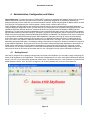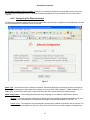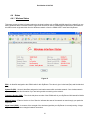
1
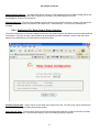
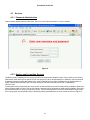
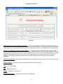
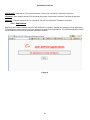
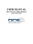
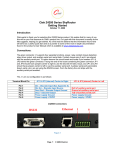
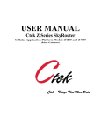
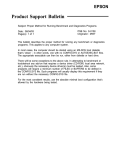
USER MANUAL
Series 4100E
Part Number 91-007-02
Firmware Release 1.02
QUALITY COMMUNICATIONS FOR INDUSTRY
Made in the U.S.A.
Part Number 91-007-02
Table of Contents
TABLE OF CONTENTS
I
PREFACE
1
1
1
INTRODUCTION
1.1
Theory Of Operation
1
1.2
Features
1
1.3
What Is In The Box
2
2
CONNECTORS, LIGHTS, SWITCHES, AND JUMPERS
3
2.1
Switches
3
2.2
Connectors
3
2.3
Lights
4
START UP
4
3.1
Power
4
3.2
Connecting The Antenna
5
3.3
Connecting to the Ethernet Port – Administrative Connection
5
3
4
ADMINISTRATION, CONFIGURATION AND STATUS
6
4.1
Getting Started
6
4.2
Interfaces
8
4.3
Services
15
4.4
Status
21
5
SPECIFICATIONS
24
6
CERTIFICATIONS
25
i
Part Number 91-007-02
Preface
Welcome to the Ctek Series 4100E SkyRouter User’s Guide. The User’s Guide will explain the basic operation of a
SkyRouter and take you through the necessary settings to get your wireless application online. Additional information and
applicable technical notices can be found at www.ctekproducts.com.
1 Introduction
SkyRouter provides application and network designers with a bridge between the world of IT infrastructure and the
evolving wireless data networks. With SkyRouter the wireless transport is fully integrated into the product’s routing fabric
meaning that you can approach the setup and operation of this product much as with any other IP addressable device.
Wireless considerations are reduced to the absolute minimum necessary to register and make connections on a network.
1.1
Theory Of Operation
The Series 4100E SkyRouter is a complete IP router that routes traffic over LAN Ethernet (10/100baseT) connections.
The wireless features of SkyRouter simply extend the IP routing capabilities to include routing and network address
translation (NAT) over CDMA2000/1XRTT wireless networks. As with most routers Ctek’s Series 4100E SkyRouter can
be viewed as having a Local Area Network (LAN) side and a Wide Area Network (WAN) side. Traffic originating at
SkyRouter’s Ethernet ports is considered LAN traffic. The Wide Area Network connection is over the wireless network’s
1XRTT transport.
1.2
Features
This manual covers SkyRouter (4100E) Release 1.00 and contains the following feature and functions.
1) Ethernet
a. Static Addressing
b. Dynamic (DHCP) Server
c. DHCP Client
d. Configurable DNS address
e. Configurable Gateway, Sub net mask, and Broadcast address
f. Port Forwarding
g. Service management
2) CDMA Interface
a. Enable/Disable Wireless Routing
b. Enable/Disable inbound IP requests
c. Adjust inactivity timers
d. Name Server Interoperability with UDP or SMS
e. DDNS Interoperability with BIND or MS Server
f. Administration web server port address selection
g. Enhanced OTA and manual activation
h. Home Network Selection
3) Relay Contact Closure (detection and operation)
a. NO/NC detection
b. SMS or email cry out alarm
4) Relay Driver Output
1
Part Number 91-007-02
a. SMS Activation
b. Web Activation
5) General Administration
a. Modify Password
6) Status – Ethernet Status
a. Currently Assigned IP Address
b. Current MAC Address
7) Status – CDMA Status
a. ESN (Serial Number) Hex and Decimal
b. Network Assigned IP Address
c. Telephone Number (MIN)
d. Current Network Status Active/Inactive
e. Signal Level (RSSI)
1.3
What Is In The Box
The following items are included with your SkyRouter
1) Series 4100 SkyRouter
2) Antenna
3) 12VDC Power adapter
4) Documentation CD
2
Part Number 91-007-02
2 Connectors, Lights, Switches, and Jumpers
2.1
Switches
Referring to Figure 1, there are two switches on the back of the Series 4100E. S1 (Reset) causes a hard reset of unit. S2
(Restore Defaults) is used to completely restore the firmware settings that were included when the product was shipped
from the factory.To restore factory defaults, the unit must be running. Press the Restore Defaults (inner) switch and hold it
down for 10 seconds. After 10 seconds, you will see both the green and yellow lights go off. At that time you may either
press the reset (outer) switch or cycle power on the unit.
Figure 1
2.2
Connectors
Ethernet Connectors
Connectors are found on the front of the Series 4100E SkyRouter. Ethernet ports 1 – 4 are auto polarity sensing and can
be used with either a standard Ethernet cable or a reverse (cross over) Ethernet cable.
Terminal Block
Connector J1 supports three separate functions, power, relay contact closure detection and the relay driver output
The pin out configuration is as follows:
Pin 1 - Relay in Sense Voltage Source 3.3vdc with over current protection
Pin 2 - Relay In Sense
Pin 3 - Relay Out Voltage Source 12vdc @40ma or less
Pin 4 - Relay Out Control
Pin 5 - Ground
Pin 6 - +12VDC
Antenna Connector - Standard SMA type female connector.
3
Part Number 91-007-02
Figure 2
2.3
Lights
The Series 4100E SkyRouter has indicators as shown in Figure 1.
The network status indicator should be interpreted as follows:
NO IP CONNECTION - When there is no connection, the led will be in the off state. If there is low signal (less than 88dBm) you will see one 200msc blink (on) every 4.5 seconds. if there is good signal quality, you will see two 200msc
blinks (on) every 4.5 seconds.
IP CONNECTION - If there is a connection, the led will be in the on state. If there is low signal, you will see one 200msc
blink (off) every 4.5 seconds. if there is good signal quality, you will see two 200msc blinks (off) every 4.5 seconds.
3 Start Up
Warning – You must connect an antenna to the SMA style antenna connector on the SkyRouter before turning it
on. Failure to do this could result in erratic start up behavior and could possibly damage the unit.
3.1
Power
Before starting connect the supplied 12VDC power adapter to the power connector described in Section 3. The adapter
supplied with your SkyRouter is suitable for use with 120VAC 60-hertz wall power. If you need a different power solution
contact Ctek.
4
Part Number 91-007-02
3.2
Connecting The Antenna
The antenna supplied with each SkyRouter should be attached to the SMA style antenna connector described in section
3. The antenna must be connected before powering the unit on.
3.3
Connecting to the Ethernet Port – Administrative Connection
For a direct Ethernet connection between a PC connect to any of the Ethernet ports using a standard or reverse Ethernet
cable. For initial configuration and administration with a PC or workstation Ctek recommends that the PC be set to obtain
an IP address and obtain a DNS address automatically. For Windows PCs make the following settings under the
networking control panel
LAN (Ethernet) Connections - Windows
Figure 3
5
Part Number 91-007-02
4 Administration, Configuration and Status
About Addressing – Devices connecting to CDMA/1XRTT networks are assigned an IP address by the serving network.
Address assignment may either be static or the unit will be dynamically assigned an IP addresses, depending on
arrangements that you have made with your wireless network operator. Dynamically assigned IP address remain in effect
for a period of time assigned by the network operator, usually at most a small number of hours.
Ctek’s SkyRouter includes features that manage the temporal nature of dynamically assigned wireless IP addresses.
Using the Wireless Configuration screen you can configure your SkyRouter to use a Dynamic DNS (DDNS) service. Ctek
operates a DDNS test bed that allows our customers to observe the performance and reliability of DDNS with their
applications. For large-scale commercial applications Ctek recommends that users configure their own DDNS, managed
and maintained with the customers ongoing IT operations. Any Series 4100 SkyRouter can be configured to operate as a
DDNS using Ctek’s proprietary Enhanced Wireless DNS (EW/UDP or EW/SMS). The SkyRouter may also be configured
to operate with a standard DNS having Dynamic DNS capabilities. Examples of this type of service would be Berkeley
Internet Name Daemon (BIND) and Microsoft Server 2000 and up. For detailed information see Ctek’s TechNote S4100-01.
Even if you elect to use a static IP address a DDNS service will add value in two ways. First, when the networks static
addressing assignment fails there is a mandatory waiting period before the endpoint is allowed to reinitiate the request for
a static address registration. During this period of time the network will dynamically assign addresses to the end point. A
DDNS service will make the end point network addressable (by name) during this period of time. Secondly, a name
service allows your end point to be known by a name that is independent of network addressing. Addressing a unit by
name may be easier for end users to remember and will, over a long period of time, reduce maintenance problems.
4.1
Getting Started
Once the PC has been set up properly and physically connected to the SkyRouter you are ready to begin configuring the
Series 4100 SkyRouter for your application. To access the Administration menu use a conventional web browser pointed
at http:// 192.168.1.10. A login screen appears as shown below. The default User ID is “ctek” (without the quotes) and the
default Password is also “ctek”. Be sure to change the user ID and password and record your new selections.
Figure 4
6
Part Number 91-007-02
When you have completed the login process you will be presented with the top-level administration menu.
Figure 5
Note that the administration menu is divided into three sections. The Interfaces section deals with physical connectivity,
managing the connection and subtended devices. Services are applications that are within the router core to modify the
behavior of a specific interface or to change system wide parameters within the router core. Status screens are provided
for the CDMA2000/1XRTT and Ethernet interfaces.
Note – The Restart button must be used to apply any changes made on specific Interface or Service screens.
7
Part Number 91-007-02
4.2
Interfaces
4.2.1 Configuring The Wireless Interface
The configuration screen for the wireless interface is shown below. The actual wireless interface is provisioned and
configured by the wireless Network Operator. SkyRouter’s Wireless Interface Configuration screen is used to establish
inactivity timeouts and Name Server selections.
Figure 6
Network Select – This pull down menu allows the user to control the home network setting of the CDMA connection,
effectively limiting the scope of the Preferred Roaming List (PRL) assigned by your wireless network operator. There are
four possible settings:
1) Auto – Auto is the standard mode of operation and should continue to be used in most cases. In the Auto mode
of network selection the entire PRL is considered for serving network connections.
2) Home Only – In Home Only mode serving network connection choices are limited to those defined as Home in
the PRL.
8
Part Number 91-007-02
3) PCS Home Only – In PCS Home Only mode serving network connection choices are limited to those PCS
(1900MHz) defined as Home in the PRL.
4) Cellular Home Only - In Cellular Home Only mode serving network connection choices are limited to those
Cellular (800MHz) defined as Home in the PRL.
Warning – If the Series 4100 SkyRouter is transported from one location to another Network Selection choices other
than Auto could cause the unit to fail to make a network connection. For instance, if the Network Selection mode was set
to PCS Home Only and the unit was transported to a location not served by PCS, or an area where the PCS network was
not included in the PRL, the connection would fail.
Ctek recommends that Auto mode should always be used unless problems are detected. If selections other than Auto are
required the user should then evaluate operation in Home Only. Network technology specific choices (PCS Home Only
and Cellular Home Only) should only be used as a last resort.
User Name and Password – Required for activation on some networks. See TechNotes for specific usage.
Connection Type – Used to manage conditions under which a wireless WAN connection will be made.
Disabled – Never connect to the wireless network
On Demand – Only connect when there is outbound traffic to route
Always On – SkyRouter remains connected to the wireless network independent of whether there is outbound
traffic or not. In this mode SkyRouter will automatically reconnect to the network if disconnected or if its IP lease
expires
Connection Inactivity Timeout – When operating in On Demand mode, this timeout parameter defines the length of time
that the SkyRouter will remain connected to the wireless network. If your Wireless Network Operator has a shorter timer it
will take precedence over this setting.
Use Network’s Dynamic IP Address – For most networks this will be the correct selection.
Use The Following Static IP Address – If your selected network is capable of provisioning a static IP address to your
application check this box and enter the assigned IP address. See TechNotes for network specific set up.
Enable LCP echo packets – For most networks under most conditions LCP echo packets should be turned off, meaning
this box should be unchecked. If your network is providing a highly managed connection you may need to turn LCP echo
packets on. If you have questions check with Ctek support.
Select DNS Type – Used to select the appropriate protocol for your Dynamic DNS.
1)
2)
3)
4)
None – DDNS will not be used.
EW/SMS – Use Ctek Enhanced Wireless DDNS with SMS updates.
EW/UDP - Use Ctek Enhanced Wireless DDNS with UDP updates over the 1XRTT Air Interface
Standard UDP – Use a standard BIND, MS2000, or MS2003 DDNS server
Device Name – Establishes the name by which this particular SkyRouter will be known at the Name Server. This entry
must be a fully qualified device name and domain and is limited to 40 characters in total. It is limited to one level of name
space definition meaning that all characters to the right of the first “dot” will be assumed to be a component of the
resolving server. An example would be ctek01.thingme.net where ctek01 is the name of an individual SkyRouter and
thingme.net is the name of the resolving server.
Primary and Secondary Name Server – Enter either phone number (SMS updates) or the IP address of the designated
Name Server. Name resolution is not performed on this entry meaning that a numeric IP address of the resolving server is
required.
9
Part Number 91-007-02
Provide Network Name Server Facilities – Selecting Yes causes this SkyRouter to provide Name Server services to
client SkyRouters configured to use it. If this option is selected additional set up in the Name Services screen will be
required.
4.2.2 Configuring The Ethernet Interace
The Ethernet configuration determines how devices connected to the LAN side of SkyRouter will be addressed, and what
the actual address of this SkyRouter will be on the LAN.
Figure 7
Media Type – Determines the type of Ethernet connection. Auto allows SkyRouter to determine what the connection is.
This setting is appropriate for most cases. Other settings are to select either 10Mb (10baseT), 100Mb (100baseT), Full
Duplex (FD), or Half Duplex (HD). Again, in almost all cases Auto will correctly determine the proper setting.
DHCP Configuration – These settings determine the network topology of the LAN side of SkyRouter’s network.
Disabled – You must manually configure the IP address and other addressing parameters described in the next
section . It is recommended that the SkyRouter be assigned a private static address of 192.168.1.10.
Enable Server - This SkyRouter must be assigned a private static IP address, as defined in the next section. It is
recommended that an address of 192.168.1.10 be used. The DHCP server will issue dynamic IP addresses to
10
Part Number 91-007-02
other devices connected to the LAN side. IP addresses will be assigned for up to 50 devices. Address assignment
is sequential in the range of 192.168.1.100 – 192.168.1.150.
Enable Client – Some other device on the LAN side of the network is acting as a DHCP server. SkyRouter will be
assigned a dynamic IP address by the DHCP server.
DNS Address Source – In most cases this parameter should be set to Acquire From Wireless Network. In this case,
when you click on the Update button, the Skyrouter will verify that it has been connected to the wireless network and that
the wireless network has provided DNS addresses. If DNS addresses have been provided, they will be displayed in the
Primary and Secondary Address boxes. If addresses have not been provided, you will receive an error indication. At that
point, you should allow the SkyRouter to establish a connection with the wireless network so that it can acquire the DNS
addresses. You should then go back into the Ethernet Configuration screen and click on submit again. At this point, the
DNS addresses should appear.
If you application requires a specific DNS setting check the User Defined box and manually fill in the DNS IP Address
fields below.
DNS IP Address (Primary and Secondary) – The address of the Domain Name Server that your network uses. This
should not be confused with the Name Server entries on the Wireless Interface screen. The DNS referenced by these
addresses will resolve outbound queries.
IP Address – The IP address assigned to the LAN segment of this SkyRouter.
NetMask – This parameter is also known as Subnet Mask. Network Mask determines which portion of an IP address is
the network portion and which portion belongs to the host. As an example a setting of 255.255.255.0 would indicate that
the first three groups of this address (255.255.255) identify the network and that the last group (000 – 254) identify a
particular host.
Default Gateway – The Default Gateway is the address of a device that SkyRouter will use to reach remote networks or
servers. In many cases this will be a firewall address. In a normal situation where the 4100 is acting as a fringe router and
is expected to pass incoming Ethernet traffic through to the CDMA network, this field should be left blank. If the 4100 is
acting as a RAS where traffic is coming in from the CDMA network so that it can be routed through to some sort of
host/server, this field must set to the address of the 4100’s Ethernet port.
Broadcast Address
If applications on the 4100 need to do a broadcast operation, this is the address that will be used on the Ethernet segment
to fulfill the broadcast request.
11
Part Number 91-007-02
4.2.3 Configuring The Relay Input Interface
This screen configures the connection characteristics of the relay input interface and defines the service associated with
this interface. Currently, the relay interface can cause an SMS message to be sent to another wireless device or an email message to be sent to any valid email address.
Figure 8
Relay Input Trigger – Establishes the conditions under which the Relay Service will be invoked. Unless it is disabled the
relay input is sampled at 1000 millisecond (1 second) intervals.
Disabled – Never respond to relay activity
On Closure – Respond when relay contacts go closed
On Opening - Respond when relay contacts go open
Maximum Trigger Rate – This setting determines how often the SkyRouter will send a “relay event” message. If the relay
event is recurring at a rapid rate this setting will prevent an undesirable “flood” of messages. If Maximum Trigger Rate is
set to "Always" the relay input is operating in edge triggered mode. In this mode the SkyRouter will invoke its assigned
service any time that the input transitions to the selected state. So if ON CLOSURE is selected an SMS is sent every time
that the contacts close. This means that once closure is sensed there can be no other closure event until the contacts are
first sensed to be open.
All other modes where Max Trigger Rate has a time value are level sensitive. So it the contacts close an SMS is sent and
then the state of the relay input is ignored for a defined period of time. For instance, if Max Trigger Rate is set to 5
minutes an SMS is sent and then the relay input is sampled again in 5 minutes. If the contacts are still closed another
SMS is sent. If the relay input is not closed SkyRouter reverts to monitoring the relay every second.
12
Part Number 91-007-02
SMS Destination Address – The MIN (mobile phone number) or email address to which the SMS message will be sent.
MIN must be 10 numeric characters with no spaces or punctuation. Any email address in the form
Anything@Any_Domain will be accepted.
SMS Alert Message – The text of the message to be sent when the relay interface activates. Limited to 100 characters
maximum. Only printable ASCII characters in the range of 32 – 126 decimal (20 – 7E hex) can be included in the
message.
4.2.4 Configuring The Relay Output (Driver) Interface
This screen configures the connection characteristics of the relay output interface and defines the service associated with
this interface. Currently, the relay output interface can be activated by an SMS message or from a button that can be
defined on the Advertising screen described in the Services section.
Set Relay Output State – Used to set the current state of the relay driver circuit. The relay driver can be activated and
deactivated by changing this setting and pressing update.
Relay Shut Off Timer – The relay driver circuit will revert to its default setting after the number of minutes or seconds
specified by this parameter. The two second setting is useful for resetting end point equipment.
13
Part Number 91-007-02
Allow SMS Control of Relay – If Yes is checked the relay driver may be activated by sending an SMS with the command
“R1” and deactivated by sending an SMS with the command of “R0”.
Allow Web Browser Control of Relay – If set to yes a button will appear on the Advertising screen to enable and disable
the relay driver circuit.
Text For Web Link To Relay – This text will appear on the advertising screen next to the relay activation button.
14
Part Number 91-007-02
4.3
Services
4.3.1 Password Administration
Used to change passwords and create users. Be sure to record this information in a secure location.
Figure 9
4.3.2 Routing and Forwarding Services
The Routing and Forwarding Services screen provides two separate but related functions. First it allows you to forward
WAN side IP traffic arriving on a specific IP Port to a specific Port at a LAN side address. In addition to this conventional
forwarding feature this screen also allows you to make a Named Service publicly available over the WAN interface. In
Figure 14 below WAN side UDP and TCP traffic arriving on Port 88 is redirected to Port 80 of LAN address
192.168.1.102.
The second function performed by this set up screen to allow named services to be made publicly available to WAN side
users. Referring again to Figure 14 a service named Camera #1 will be advertised or made publicly available. Security for
this advertised service is left up to the specific service. If the Advertising feature is used the Administrative Login screen
will no longer greet incoming WAN users, instead they will be presented with a Services screen as shown in Figure 15.
15
Part Number 91-007-02
Figure 10
Block Inbound IP Traffic From Wireless Network – If set to Yes the SkyRouter’s firewall is configured to block any
inbound originated (but not response) packets from the wireless network (WAN). This firewall is then selectively modified
by the forwarding entries defined through this screen. If this parameter is set to No, the SkyRouter’s firewall is disabled.
Use NAT on all Ethernet traffic to wireless network – For normal operation this parameter should be set to “Yes”. In
some unique situations, you may connect the SkyRouter to a network where you will be given public address to use on
your LAN’s Ethernet segment. In such cases, NAT should be turned off. NAT is currently required for operation on all US
networks such as Sprint, Verizon or Alltel. Typical environments where NAT would be turned off would be private
networks or some types of VPNs and in these cases, the network operator will most likely provide configuration
assistance.
Forward Inbound Port – This table allows WAN side packets addressed for specific IP ports to be routed to a specified
address on the LAN side.
Of Local Address – Used to specify the LAN side address of the routing operation.
TCP – Route TCP/IP traffic
UDP – Route UDP/IP traffic
Enable – Activate this routing setting
Advertise This Service – Display this named service for WAN users
16
Part Number 91-007-02
With Title – The name assigned to this service
Figure 11
17
Part Number 91-007-02
4.3.3 Admin Screen Services
This service allows the user to control overall local and remote administrative access.
Figure 12
Port Number For Admin Screen Access – Causes the WAN side web server to listen on a port other than the default of
Port 80.
Allow Network Access To Admin Screens – If set to Yes administrative users will be able to connect to SkyRouter’s
Admin interface over the 1XRTT network connection. If this selection is set to No only local administration is possible.
18
Part Number 91-007-02
4.3.4 Over The Air (OTA) Programming
Almost all CDMA2000 networks employ one form or another of OTA to refresh Preferred Roaming Lists (PRL) and to
make other programmatic changes to the firmware associated with the wireless interface. Some networks have
streamlined the entire process into a single command that performs the activation and downloads the required data files.
In other cases a series of command steps are require to do a complete activation. The OTA programming function allows
you to enter the required short codes to accomplish Over The Air Programming on the network that you are using. Any
single command line can be entered on the OTA screen. This command line will be sent directly to the CDMA radio and
from there to the wireless network. The OTA screen will display a single line of response from the network. Ctek publishes
TechNotes on the activation procedures for different networks.
Note – Before using the OTA screen, you must:
• Go to the Wireless Interface Screen and disable the WAN interface of your SkyRouter.
• Perform a Restart of your SkyRouter.
These steps terminate any packet or circuit connection with the network so that OTA operations may take place with no
interference. Once the OTA programming is completed you will need re-enable the WAN interface and restart your
SkyRouter to re-establish network connections.
Figure 13
19
Part Number 91-007-02
SPC (Unlock) – Required for OTA on some networks. Consult Ctek’s Activation TechNotes for specifics.
Command – Enter network specific OTA commands in this field. Consult Ctek’s Activation TechNotes for specifics.
Response – Network responses to OTA commands. Consult Ctek’s Activation TechNotes for specifics.
4.3.5 Applications
Beginning with Firmware Release 2.02 the 4100S SkyRouter is capable of installing and managing custom applications.
The Applications Services screen is the user interface to manage custom applications. The individual application release
documentation will document the individual applications behavior.
Figure 14
20
Part Number 91-007-02
4.4
Status
4.4.1 Wireless Status
This status screen provides information about the wireless interface such as ESN and MIN that will be needed if you are
having problems with the wireless network. Signal level can also be used to validate antenna placement. Information on
this status screen originates either from the Wireless network or from the CDMA/1XRTT radio within SkyRouter.
Figure 15
ESN – An identifier assigned to the CDMA radio for this SkyRouter. The value is given in decimal (Dec) and Hexidecimal
(Hex).
System ID (SID) – Numeric Identifiers assigned to local market areas within a wireless network. Your wireless network
operator may request this information if you are having trouble connecting to the network.
Telephone Number (MIN) – The circuit side phone number of the CDMA radio in your SkyRouter. MIN stands for Mobile
Identification Number.
Network Status – Either In Service or Out of Service. Indicates the state of the network as seen through your particular
SkyRouter.
Signal Level (RSSI) – A measure of the strength of the wireless signal that your SkyRouter is currently seeing. A larger
negative number indicates a marginal network connection.
21
Part Number 91-007-02
Roam Status – Indicates the network’s view of the current geographic location of your SkyRouter. The possibilities are
Not Roaming (Home), Roaming, or Blink Roaming. An indication of Roaming may or may not impact your data
transmission costs. Charges are a function of your rate plan, not necessarily linked to the networks notion of roaming.
Note also that Off Network Roaming is not supported by most 1XRTT packet networks today but may be in the future.
Current IP Address – If the Current Status field is Active this is the IP address that the wireless network has assigned to
your SkyRouter during this registration. If Current Status is inactive this is the last IP address assigned.
Call Type – Text provided by the wireless network indicating the type of call that is in progress.
No Call In Progress
Circuit Switched – A Circuit Switched Data (CSD) call has been established
Packet – Relay Model - 1XRTT packet call using IP services provided by the endpoint
Packet – Network Model - 1XRTT packet call using IP services provided by the network
Packet – Mobile IP – Advanced packet type call supporting roaming and handoff
Call Status – Indicates the current status of network registration
Idle - - Not registered (disconnected)
Connected – Registered and active on the network
Dormant – Registered but inactive
Ended – The current call has been terminated
22
Part Number 91-007-02
4.4.2 Ethernet Status
Indicates the current LAN side IP address that the SkyRouter is using. MAC Address is a vendor and machine specific
identification code.
Figure 16
23
Part Number 91-007-02
5 Specifications
Controller
Axis Etrax 100LX MCM 4+16
Linux 2.4
Interfaces
Four Port Ethernet Switch - RJ45 Ethernet 10/100baseT Full or Half Duplex auto polarity sensing
Relay Input Interface - Designed to detect closure or opening of relay contacts.
Physical – 2 Pin Terminal Block
Electrical – Self-powered, current limited loop senses state of relay contacts. No external power required.
Maximum cable length between Series 4100 and relay - 50 feet
Relay Output Interface
Physical – 2 Pin Terminal Block
Electrical – Self-powered 40ma @12VDC
Wireless Interface
CDMA2000/1XRTT
Physical – SMA Antenna (removable)
CDMA Approvals – Compliant with: IS-95, CDMA 2000 specifications. FCC: Part 22, 24 and 15.
Power Requirements
Standard - 12VDC ± 10%.
115VAC -> 12VDC Wall Transformer included.
Power Consumption @12VDC nominal
CDMA Radio Off - 180ma
CDMA Radio On – Data Channel Inactive – 230ma
CDMA Radio On - 1 Ethernet Port Connected – 384ma
CDMA Radio On – 4 Ethernet Ports Connected – 445ma
Environmental
Operating temperature range: - 20C to +70C. Humidity: 90% non-condensing.
Physical
Dimensions: 5.275"L x 5.225"W x 2.08"H. Weight: 12oz.
Mounting – Self standing or wall mount
24
Part Number 91-007-02
6 Certifications
FCC Part 15
This equipment has been tested and complies with the limits for a Class A computing device according to U.S. Code of
Federal Regulations, Title 47, FCC Rules and Regulations Part 15. Operation is subject to the following two conditions:
1) This device may cause harmful interference, and
2) This device must accept any interference received, including interference that may cause undesired
operation.
Test Report
FCC - Report # SC400074-06
Industry Canada - # SC400074-06A
Testing for compliance with Measurement Requirements (CFR 47 Part 22, Paragraph 22.917(b)(2) and Part 24,
Paragraph 24.238(a))
FCC – Report # SC400074-03
Industry Canada – Report # SC400074-03A
WARNING: To reduce any possible hazard due to exposure of the human body to electromagnetic
radiation, per FCC OET Bulletin 65, this device is approved for operation using the antenna provided.
The antenna installation must provide a separation distance of 20 cm or more between the antenna
and all persons to satisfy Maximum Permissible Exposure (MPE) compliance.
25