1
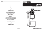
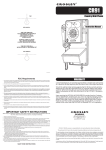
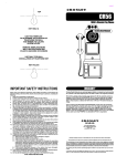
TOP
CR56
1950’s Classic Pay Phone
KEY HOLE A
Instruction Manual
USE THIS TEMPLATE
TO DETERMINE THE POSITION OF
TELEPHONE ON WALL,
AND WHERE TO LOCATE
SCREW HOLES.
REMOVE TEMPLATE FROM
WALL BEFORE INSERTING
PLASTIC ANCHORS OR SCREWS
USE ONLY FOR WALL
INSTALLATION OF TELEPHONE SET
KEY HOLE B
IMPORTANT SAFETY INSTRUCTIONS
When using your telephone equipment, basic safety precautions, should always be
followed to reduce the risk of fire, electric shock and injury to persons, including the
following:
1. Read and understand all instructions.
2. Follow all warnings and instructions marked on the product.
3. Unplug this product from the wall outlet before cleaning. Do not use
liquid cleaners or aerosol cleaners. Use a damp cloth for cleaning.
4. Do not use this product near water, for example, near a bathtub, wash bowl,
kitchen sink, or laundry tub, in a wet basement, or near a swimming pool.
5. Do not place this product on an unstable cart, stand, or table. The product may
fall, causing serious damage to the product.
6. Slots and openings in the cabinet and back or bottom are provided for ventilation,
to protect it from overheating, these openings must not be blocked or covered.
The openings should never be blocked by placing the product on the bed, sofa,
rug, or other similar surface. This product should never be placed near or over
a radiator or heat register. This product should not be placed in a built-in
installation unless proper ventilation is provided.
7. This product should be operated only from the type of power source indicated
on the marking label. If you are not sure of the type of power supply to your
home, consult your dealer or local power company.
8. Do not allow anything to rest on the power cord. Do not place this product
where the cord will be abused by persons walking on it.
9. Some telephones require AC power from the outlet. Do not overload wall outlets
or extension cords as this can result in the risk of fire or electric shock.
10. Never push objects of any kind into the product through cabinet slots as they
may touch dangerous voltage points or short out parts that could result in a
risk of fire or electric shock. Never spill liquid of any kind on the product.
11. To reduce the risk of electric shock, do not disassemble this product, but take
it to a qualified serviceman if service or repair work is required. Opening or
removing covers may expose you to dangerous voltages or other risks. Incorrect
reassembly can cause electric shock when the appliance is subsequently used.
12. Unplug this product from the wall outlet and refer servicing to qualified service
personnel under the following conditions:
A. When the power supply cord or plug is damaged or frayed.
B. If liquid has been spilled on the product.
C. If the product has been exposed to rain or water.
D. If the product does not operate normally by following the operating
Instructions, adjust only those controls that are covered by the operating
instructions. Improper adjustment of other controls may result in damage
and will often require extensive work by a qualify technician to restore the
product to normal operation.
E. If the product has been dropped or the cabinet has been damaged.
F. If the product exhibits a distinct change in performance.
13. Avoid using a telephone (other than a curdles type) during an electrical storm.
There may be a remote risk of electric shock from lightning.
14. Do not use the telephone to report a gas leak in the vicinity of the leak.
SAVE THESE INSTRUCTIONS
WARRANTY
Crosley Radio Products are warranted against defects in material and
workmanship for a period of 90 days beginning from the date of sale to the
original purchaser.
Should the unit fail under normal usage during the 90 day warranty period, a
request for RETURN AUTHORIZATION (R.A.) must be made by the original
customer before returning the unit. Call Crosley Radio customer service for
Return Authorization at (502) 583-4246 from 9 AM to 5 PM (EST) Monday to
Friday.
Upon receiving the RETURN AUTHORIZATION number from the Customer
Service Department, properly pack your unit in its original packaging. Include
any adapters, parts, & accessories which were originally provided with the
product, along with a check or money order for $19.95 made out to Crosley
Radio to cover the handling and return postage. Display the R.A. # on the
outside of the carton and ship PREPAID via standard UPS or its equivalent.
ATTN: RETURNS DEP'T
2001 PRODUCTION DRIVE
BAY 2 & 3
LOUISVILLE, KY 40299
CROSLEY RADIO assumes no responsibility for units sent without prior Return Authorization.
The purchaser’s bill of sale is the only proof of warranty entitlement and must accompany the unit.
The warranty does not cover damage due to acts of nature, accident, misuse, abuse, negligence, commercial
use or modification of, or to any part of the product. This warranty does not cover damage due to improper
operation or maintenance, connection to improper voltage supply, or attempted repair by anyone other than
a facility authorized by Crosley Radio to service the product. This warranty does not cover products sold
AS IS or consumables (such as fuses or batteries). This warranty is valid only in the United States.
This warranty gives the purchaser specified legal rights in addition to any rights which may vary from state
to state.
In accordance with the "Moss-Magnuson Warranty Act" of July 10, 1975, this is termed a "limited warranty"
which in no way compromises Crosley Radio‚ high standards of Quality and Workmanship.
SET UP
DIAL MODE
TABLE
Locate the DIAL MODE switch on the rear of the telephone body. Slide the switch to
TONE unless you have Dial-Pulse (Rotary) telephone service in your area in which case,
slide the switch to the PULSE position.
RINGER CONTROL
1. Connect 7 foot line cord to LINE CORD jack on the rear of the telephone body.
2. Plug free end of line cord into nearest modular telephone jack.
MAKING AND ANSWERING CALLS
To get a dial tone or answer an incoming call, lift the handset.
To hang up, either replace the handset or simply press down the HANDSET CRADLE.
The RINGER CONTROL switch on the rear of the telephone body allows you to turn the
ringer OFF or set it to ring at either NORMAL or HIGH volume. You can still make or
receive calls with the ringer in OFF position, however, you will not hear the incoming
ring.
REDIAL
RECEIVER VOLUME
COINBOX
HANDSET CORD
TROUBLESHOOTING
The RECEIVER VOLUME CONTROL switch, located on the rear of the telephone body,
allows you to adjust the volume of the receiver earphone from LO, MED and HI.
To assemble, insert the end of the handset cord into the HANDSET CORD JACK located
on the left side of the telephone body.
The last number dialed is automatically stored in the phone. To redial the last number,
lift the handset and press the REDIAL (coin release) button.
Coins can be deposited into the COIN SLOTS located on the top of the telephone body.
The coins will ring a bell and drop into the coin box. The coinbox may be opened by
inserting the key and rotating.
If you experience problems with your telephone, try the following suggestions:
NO DIAL TONE
INSTALLATION
MODULAR WALL JACK
To install the telephone directly on a modular wall jack :
1. Connect the 15 inch line cord to the LINE CORD jack on rear of telephone body.
2. Tuck the line cord into the channel on the back of the phone.
3. Peel and stick the rubber pads on the back side of the phone in the 4 corners.
4. Hold the telephone body up next to the modular jack and plug the line cord into this
jack.
5. Tuck the excess line cord into the recess provided on the back of the phone.
6. Line up the mounting holes of the telephone body with the mounting studs (screw
heads) on the modular jack or wall.
7. Push the telephone body against the wall jack and gently pull down.
WALL
If you are not mounting directly onto a modular wall jack, proceed as follows :
1. Install the 7 foot line cord into the LINE CORD jack on the back of the telephone. If
the desired location is farther than 7 foot from a wall jack, you will have to obtain a
longer line cord available at most hardware stores.
2. Place the provided TEMPLATE against the wall in the position desired.
3. Mark the wall by poking either a pen or pencil through the indicated spots on the
template.
4. If there is no stud at this location, it will be necessary to install the provided wall
anchors. Drill a small pilot hole at the marked locations. Tap the anchors into the
holes. Then insert screws, but DO NOT TIGHTEN. Leave the screw heads protruding
about ¼ inch.
5. If there is a stud at this location, simply install the two screws into the stud. REMEMBER,
leave screw head protruding.
6. Telephone is then mounted according to procedure detailed in MOUNTING TO
MODULAR PLUG.
1. Make sure that all plugs are connected properly. Check the connections at the wall
jack, the telephone body and the handset.
2. Try another modular jack within your home which you know to be working properly.
CALLS CANNOT BE DIALED OR DIALED SLOWLY
Check to make sure that the DIAL MODE switch is in the correct position for the type
of service available in your area.
TELEPHONE DOES NOT RING
Check that RINGER CONTROL switch is not set to OFF.
If there are several telephones connected to the same line, try disconnecting some of
the other telephones. Having too many telephones connected to the same line can cause
low ringer volume or poor sound quality during calls.
CARE AND MAINTENANCE
Avoid rough treatment to your telephone. Do not drop the handset and always replace
it gently onto the cradle.
Clean only with a cloth slightly dampened with water only. Do not use detergents, waxes,
solvents, sprays, alcohols or excessive water.
PARTS INCLUDED
Your new telephone includes the following items:
1 - Telephone handset
2 - Screws with wall archors
1 - Handset coil cord
4 - Rubber spacer pads.
1 - Telephone body
2 - Tapping screw
1 - 7 Foot line cord
1 - Template (See above picture and instructions)
1 - 15 Inch line cord
NOTE : If you encounter difficulty fitting the telephone body onto the screws, or the
telephone wobbles when installed, either tighten or loosen the screws to adjust.
TO INSTALL WALL ANCHORS
If the location you have chosen to mount your telephone is a hollow wall without any beams you will
have to use the included wall anchors.
LOCATION OF PARTS
To install, place the template against the wall where you wish to place your telephone. Mark the wall
at the location of the two + on the template by pushing a pen or pencil through the template. Drill a
1/4" hole at each mark.
With a Phillips screwdriver, begin tightening the screw by turning it clockwise. Stop turning when you
feel firm resistance.
Turn the screw counter clockwise until the screw head is about 1/4" out of the wall.
DIAL
REDIAL BUTTON
( coin release)
TELEPHONE BODY
Install the 7 foot line cord at back of the telephone . Adjust the switches to your preference. Position
the line cord through the slot on the bottom of the cabinet. Line up the holes with the two screws. Place
the telephone onto these two screws and gently pull down.
MOUNTING HOLES
This may require a little fine tuning until the phone is seated securely.
WALL ANCHOR
PRIOR TO INSTALLATION
1/4" HOLE
COIN SLOTS
HANDSET
CRADLE
RINGER
CONTROL
HI
LOW
OFF
HANDSET
DIAL
MODE
TONE
PULSE
WALL
AFTER INSTALLATION
RECEIVER
VOLUME
HI
MED
LO
HEADSET
CORD JACK
INSTRUCTION TO USE
FCC Registration Information
HEADSET
CORD JACK
HANDSET
CORD
CHANNEL
LINE CORD JACK
This equipment complies with Part 68 of the FCC rules. On the lower side of the equipment is a label
that contains, among other information, the FCC registration number and the Ringer Equivalence.
Number (REN) for this equipment. If requested, provide this information to your telephone company.
The REN is useful to determine the quantity of devices you may connect to your telephone line.
Excessive REN’s on the telephone line may result in the devices not ringing in response to an incoming
call. In most areas, but not all areas, the sum of the REN’s should not exceed five (5.0). To be certain
of the number of devices you may connect to you lines, as determined by the REN, you should call your
local telephone company to determine the maximum REN for your calling area.
If your telephone equipment causes harm to the telephone network, the telephone company will notify
you in advance that temporary discontinuance of service may be required. But if advance notice is not
practical, the telephone company will notify the customer as soon as possible. Also you will be advised
of your right to file a complaint with the FCC if you believe it is necessary.
SPACE PADS
COIN BOX
910-008800-008