1
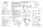
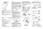
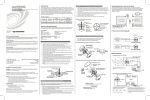
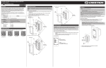
Crestron GLS-LOL
(Wattstopper P/N LS-290C)
PHOTOCELL LIGHT SENSOR
Operations & Installation Guide
DESCRIPTION
The GLS-LOL is a low voltage photocell which senses light levels and signals this data
to an interface device such as the GLS-SIM connected to the Crestron® control system.
GLS-LOL Specifications
SPECIFICATION
DETAILS
UL and cUL Listed
Class 2
Power Consumption
0.2W (8mA @ 24VDC)
Output
Signal Range:
Light Level Range:
0 - 10VDC
Selectable, 3 to 300 footcandles (fc),
30 to 3000fc, 60 to 6000fc
Recommended Mounting Location
Field of View Coverage
Directly above work space
60° Cone
Photocell Placement
The photocell is designed for mounting in a dry location that views daylight. The photocell
should not directly view illumination from an electric light source. The following figure
shows the GLS-LOL field of view.
Field of View & Mounting
2.0 in.
(5.08 cm)
FCC Compliance Statement:
This device complies with part 15 and part 18 of the FCC rules. Operation is subject to the following
two conditions: (1) This device must not cause harmful interference, and (2) This device must accept
any interference received, including interference that may cause undesired operation.
Ceiling tile or drywall
1.2 in.
(3.05 cm)
45º
60º field of view
Further Inquiries
If you cannot locate specific information or have questions after reviewing this guide, please take
advantage of Crestron's award winning customer service team by calling Crestron at
1-888-CRESTRON [1-888-273-7876].
You can also log onto the online help section of the Crestron website (www.crestron.com/onlinehelp) to
ask questions about Crestron products. First-time users will need to establish a user account to fully
benefit from all available features.
GLS-LOL
30º
Peak
30º
sensitivity
Future Updates
As Crestron improves functions, adds new features and extends the capabilities of the GLS-LOL units,
additional information may be made available as manual updates. These updates are solely electronic
and serve as intermediary supplements prior to the release of a complete technical documentation
revision.
Check the Crestron website periodically for manual update availability and its relevance. Updates are
identified as an “Addendum” in the Download column.
Where windows are the primary source of daylight, the photocell typically mounts on the
ceiling between the window and the first row of fixtures. (Refer to the following figure.) The
photocell points toward the window.
Placement
45°
Crestron Electronics, Inc.
15 Volvo Drive Rockleigh, NJ 07647
Tel: 888.CRESTRON
Fax: 201.767.7576
www.crestron.com
Cable to GLS-SIM or other
compatible Crestron interface
device.
Operations & Installation Guide-DOC. 6774A
(2023057)
12.08
Specifications subject to
change without notice.
Peak
Sensitivity
GLS-LOL
Light Fixture
Window
WARNINGS, CAUTIONS & NOTES
WARNING: To avoid fire, shock, or death; turn off power at circuit breaker or fuse and
test that power is off before wiring!
CAUTION: Insufficient power can lead to unpredictable results or damage to the
equipment. Please use the Crestron Power Calculator to help calculate how much power
is needed for the system. (www.crestron.com/calculators).
NOTES: Observe the following points regarding sensor installation.
• To be installed and/or used in accordance with appropriate electrical codes and
regulations.
• If you are unsure about any part of these instructions, consult a qualified electrician.
• Sensors must be mounted on a vibration free surface.
• All sensors must be mounted at least 6 feet away from air vents.
NETWORK WIRING
For skylight applications, the photocell mounts in the lightwell of the skylight and should
view the incoming daylight. Typically, the photocell is aimed toward the skylight. The light
level range adjustment jumper may need to be changed to 60-6000fc for skylight
applications.
Light Level Testing
Before installing the photocell, verify the daylight levels on a sunny day at the proposed
location of the photocell. With the lights switched off, use a light meter to read the daylight
level. Orient the light meter in the same direction that the photocell will view. The light
levels under sunny conditions must be at least 35fc. If the light levels are less, you should
select another location or reorient the photocell.
When wiring the Cresnet® network, consider the following:
• Use Crestron Certified Wire.
• Use Crestron power supplies for Crestron equipment.
• Provide sufficient power to the system.
INSTALLATION
PREPARING AND CONNECTING WIRES
Strip the ends of the wires approximately 1/2”. Use care to avoid nicking the conductors.
Twist together the ends of the wires that share a connection and tin the twisted
connection. Apply solder only to the ends of the twisted wires. Avoid tinning too far up
the wires or the end becomes brittle.
Use CRESNET-P/-NP cables only. Maximum distance is 250 feet.
Wiring and Testing
1.
2.
To access the GLS-LOL wiring terminals, insert a small, flatblade
screwdriver into a slot on the housing and remove the base from the lens
assembly.
Review the “MOUNTING” section on the next page to determine how the
cable to the controller will enter the photocell housing. Modify either the
lens housing or the base as instructed in step 2A or 2B.
3.
4.
5.
6.
Connect wiring to the control system as shown in the diagrams to the right. (If
flush mounting, feed the cable through the base before terminating.)
Make sure the footcandle range jumper is in the correct position for the
expected light level. (Refer to “Range Adjustment” below, and the control
system instructions for information about photocell range adjustment.)
Return the base to the lens assembly.
a) Align the arrow and sun icon inside the base with the lens.
b) Use gentle pressure to snap the parts together.
Power-up the controller. Verify the photocell wiring by reading the controller
display. As you cover and uncover the photocell, the reading should change.
The controller reading shows the minimum value of the programmed range if
the light level is below the range, or if the photocell is not properly connected.
Connecting Sensors to the GLS-SIM
All wires from sensor to GLS - SIM
must be 24 AWG minimum
.
Orange
Black
GLS-SIM
Red
––– NET–––
24 Y Z G
–SENSOR–
24 1 2 G
Range Adjustment
To Control
System
The 2-pin jumpers next to the wiring terminals set the light level range for the GLS-LOL. In
most applications, the default range of 30 to 3000 footcandles is appropriate. If the range
needs to change (e.g., 3-300fc for darker applications, 60-6000fc for skylight applications)
be sure the control system programming is adjusted accordingly.
Use CRESNET-P or
CRESNET- NP wire only
Connecting Sensors to the DIN-IO8 or Equivalent*
White**
Orange
MOUNTING
G 1 2 3 4
G 1 2 3 4
––– I/O –––
After selecting a location and wiring it to the control system, test for the optimum lens
orientation before permanently mounting the photocell.
The GLS-LOL comes with a circular piece of double-sided foam adhesive tape. You can use
this tape to temporarily mount the photocell during placement testing.
DIN-IO8
Black
CAUTION: The tape may permanently adhere to some surfaces. The surface may be
damaged if the tape is removed.
The GLS-LOL can be mounted so that the cable enters through the photocell base and is
not visible (flush mount) or so that the cable exits the side of the lens assembly and runs
along the exterior of the ceiling or wall (surface mount). Refer to the figures in the right
column as necessary during mounting procedures.
1.
2.
3.
4.
5.
6.
7.
Remove the base from the lens assembly.
Open a wire entry location in either the Base or the Lens Assembly.
A.
Flush Mount (wire entry through base). Use this mounting procedure when
the wires will be concealed within the wall or ceiling.
1)
Put the base on a sturdy, flat surface so that the inside of the base is
on the flat surface and the outside of the base is facing you. Locate
the horseshoe shaped area in the center of the base.
2)
Apply firm pressure to the center of the horseshoe with a punch tool
and tap with a hammer to knockout the wire entry.
3)
Thread the cable from the controller through the outside of the base
toward the inside.
- OR B.
Surface Mount (wire entry through lens assembly). Use this procedure
when the wires will run on the surface of the wall or ceiling.
1)
Locate the wire entry location in the opaque white plastic cover at
the opposite side from the translucent lens opening.
2)
Use needle-nose pliers or wire cutters to break away the white plastic
covering of the wire entry.
Connect the wires to the terminals on the lens assembly as shown in the
connection diagrams.
Return the base to the lens assembly.
A.
Align the arrow and sun icon inside the base with the lens opening.
B.
Use gentle pressure to snap the parts together.
Remove the opaque white cover from the photocell. Insert a thin screwdriver
blade between the white cover and the lens opening, then pop off the white
cover.
Secure the photocell with screws (not provided). Use two #4 screws of the
appropriate length. For ceiling tiles, use machine screws with appropriate
washers and nuts. Use wood or masonry screws for solid surfaces. The “Field
of View & Mounting” figure on the first page shows flush mounting to a ceiling
tile or drywall using machine screws, washers and wing nuts.
Insert screws through the mounting holes as shown in the last figure in the next
column. Make sure the placement and orientation is the same as it was during
testing. Tighten the screws and fastening hardware.
Snap the white cover in place over the lens assembly.
––– NET –––
24 Y Z G
24 Y Z G
Red
To Control
System
Red**
Blue**
-P or
Use CRESNET
CRESNET-NP wire only
*The following Crestron devices may be used
to integrate the sensors into a Cresnet system
by following the schematic shown here:
DIN-IO8 DIN-AP2 PAC2
PRO2
AV2
CP2E
MP2E
CNXIO16
Any Crestron product with Versiports
NOTE: The same Crestron power supply MUST be
used to power both the sensors and the interface
device (e.g., DIN-IO8). Otherwise, there is a risk of
damage to the interface device.
** 250 feet max.
Removing Base From Lens Assembly
Lens Opening
Base
Lens
Assembly
Slot
Wire Entry Locations
Base
Transluscent
Lens Assembly
1 2 3
- OR -
Surface Mount
Flush Mount
Removing the cover from the photocell for mounting
TROUBLESHOOTING
PROBLEM
Lights don’t respond to
change in ambient light
level.
POSSIBLE
CAUSE
CORRECTIVE
ACTION
Incorrect wiring between
sensor and GLS-SIM (or
other compatible interface.
Refer to the wiring diagrams
in the right column.
Improper sensor location.
Verify that sensor is located
such that it can detect the
desired workspace light
levels.
Improper control system
programming
Check logic in control
processor or contact Crestron
for assistance.
Outside
Lens Assembly
Transluscent
Lens Opening
Opaque
White Cover
Mounting Holes
for #4 Screws