1
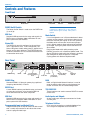
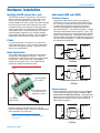
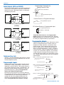
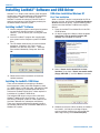
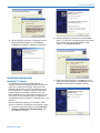
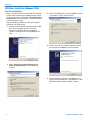
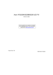
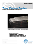
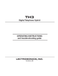
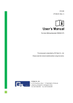
INSTALLATION and QUICK START GUIDE
DMTH4
Digital Telephone Hybrid
Fill in for your records:
Serial Number:
Purchase Date:
Rio Rancho, NM, USA
www.lectrosonics.com
DMTH4
2
LECTROSONICS, INC.
Installation Guide
Important Safety Instructions
This symbol, wherever it appears, alerts you to the presence of uninsulated dangerous voltage inside the
enclosure -- voltage that may be sufficient to constitute a risk of shock.
This symbol, wherever it appears, alerts you to important operating and maintenance instructions in the
accompanying literature. Please read the manual.
1) Read these instructions.
2) Keep these instructions.
3) Heed all warnings.
4) Follow all instructions.
5) Do not use this apparatus near water.
6) Clean only with a dry cloth.
7) Do not block any ventilation openings. Install in accordance with the manufacturer's instructions.
8) Do not install near any heat sources such as radiators, heat registers, stoves, or other apparatus (including
amplifiers) that produce heat.
9) Do not defeat the safety purpose of the polarized or grounding-type plug. A polarized plug has two blades with
one wider than the other. A grounding type plug has two blades and third grounding prong. The wider blade or
the third prong are provided for your safety. If the provided plug does not fit into your outlet, consult an electrician for replacement of the obsolete outlet.
10) Protect the power cord from being walked on or pinched particularly at plugs, convenience receptacles, and the
point where they exit from the apparatus.
11) Only use attachments/accessories specified by the manufacturer.
12) Use only with the cart, stand, tripod, bracket, or table specified by the manufacturer, or sold with the apparatus.
When a cart is used, use caution when moving the cart/apparatus combination to avoid injury from tip-over.
13) Unplug this apparatus during lightning storms or when unused for long periods of time.
14) Refer all servicing to qualified service personnel. Servicing is required when the apparatus has been damaged
in any way, such as power-supply cord or plug is damaged, liquid has been spilled or objects have fallen into the
apparatus, the apparatus has been exposed to rain or moisture, does not operate normally, or has been
dropped.
15) WARNING -- TO REDUCE THE RISK OF FIRE OR ELECTRIC SHOCK, DO NOT EXPOSE THIS APPARATUS
TO RAIN OR MOISTURE.
Rio Rancho, NM
3
DMTH4
Table of Contents
Important Safety Instructions .................................................................................................................................................................. 3
Table of Contents ...................................................................................................................................................................................... 4
Introduction ................................................................................................................................................................................................ 5
Unpacking the unit ................................................................................................................................................................................... 5
Controls and Features .............................................................................................................................................................................. 6
Front Panel ............................................................................................................................................................................................... 6
POWER On/Off Switch ........................................................................................................................................................................ 6
USB Port .............................................................................................................................................................................................. 6
Status LED ........................................................................................................................................................................................... 6
Rear Panel ............................................................................................................................................................................................... 6
POWER Plug ........................................................................................................................................................................................ 6
RS232 Port ........................................................................................................................................................................................... 6
USB Port .............................................................................................................................................................................................. 6
Programmable Input and Output Ports ................................................................................................................................................ 6
Mode Switch ......................................................................................................................................................................................... 5
DANI ..................................................................................................................................................................................................... 5
TEL/CODEC RC .................................................................................................................................................................................. 5
Audio Inputs and Outputs .................................................................................................................................................................... 5
Telephone Set/Line .............................................................................................................................................................................. 5
Hardware Installation ................................................................................................................................................................................ 7
Installing the DM system into a rack ........................................................................................................................................................ 7
Cables ...................................................................................................................................................................................................... 7
Audio Connections ................................................................................................................................................................................... 7
Audio Inputs (AUX and CODEC) ............................................................................................................................................................. 7
Unbalanced Sources ............................................................................................................................................................................ 7
Balanced Sources ................................................................................................................................................................................ 7
Audio Outputs (AUX and CODEC) .......................................................................................................................................................... 8
Telephone Line Jack ................................................................................................................................................................................ 8
Programmable Inputs .............................................................................................................................................................................. 8
Programmable Outputs ............................................................................................................................................................................ 8
Expansion I/O ports ................................................................................................................................................................................. 9
CODEC and TEL Remote Control Ports ................................................................................................................................................. 9
Installing LecNet2™ Software and USB Driver ................................................................................................................................... 10
Installing LecNet2™ Software ............................................................................................................................................................... 10
Installing the LecNet2™ USB Driver ..................................................................................................................................................... 10
USB driver installation Windows XP ...................................................................................................................................................... 10
First Time Installation ......................................................................................................................................................................... 10
Installation of Additional Units (or LecNet 2™ devices) .................................................................................................................... 11
USB Driver Installation (Windows 2000) ............................................................................................................................................... 12
First Time Installation ......................................................................................................................................................................... 12
Basic System Setup ................................................................................................................................................................................ 13
Control System Interconnections .......................................................................................................................................................... 13
Initial Setup ............................................................................................................................................................................................ 13
Master/Slave Configuration ................................................................................................................................................................... 14
Using the DMTH4 Control Panel to Change Master/Slave Mode ......................................................................................................... 14
Initial Setup Hints ................................................................................................................................................................................... 15
Example Teleconferencing Setup .......................................................................................................................................................... 16
Setting up the DMTH4 Main Matrix ....................................................................................................................................................... 17
Setting up the DM1624 Main Matrix ...................................................................................................................................................... 17
Setting up the DM1624 Expansion Matrix ............................................................................................................................................. 17
Setting up the DMTH4
Output Source Multiplexer ................................................................................................................................................................. 18
Basic System Operation ......................................................................................................................................................................... 19
Making a Phone Call ............................................................................................................................................................................... 19
Make a Telephone Call Using a Telephone Set ..................................................................................................................................... 19
Make a Telephone Call Using the Activity Tab ...................................................................................................................................... 19
Using the Touch Tone Pad ..................................................................................................................................................................... 19
Use the “Type the number to dial” box ................................................................................................................................................... 20
Use the Phone Book .............................................................................................................................................................................. 20
Setting Up Automatic Telephone Answer and Automatic Disconnect ................................................................................................... 20
Connecting to the CODEC Interface using the Activity Tab .................................................................................................................. 21
FCC Part 68 Compliance ....................................................................................................................................................................... 22
FCC Part 15 Compliance ....................................................................................................................................................................... 22
Warranty .................................................................................................................................................................................. Back Cover
4
LECTROSONICS, INC.
Installation Guide
Introduction
The purpose of this guide is to assist in the setup and
operation of a typical DMTH4 system. This guide
assumes familiarity with the DM Series Digital Audio
Processors, its components and software menus and
setup screens. To get the most out of the DMTH4
system, it is suggested to review the information
presented in the DMTH4 Series Reference Manual.
A detailed Help is also available to assist in the setup
and operation of a DMTH4 system using the USB
interface and a Windows® 2000 or Windows® XP
computer system. In addition to assistance setting up
and operating the DMTH4 system, the Help files include
a complete listing of the DMTH4 Serial Commands.
These commands can be used to setup and operate
the DMTH4 system via external devices using either the
USB or RS232 serial port.
Unpacking the unit
Compare the packing list enclosed with the unit with the
original order. Inspect all items for damage. Immediately call 1-800-821-1121 to report any items that are
missing or damaged. The sooner we get notified, the
sooner we can get any needed replacement items
shipped to your location.
Rio Rancho, NM
5
DMTH4
Controls and Features
Front Panel
R
TELEPHONE HYBRID INTERFACE
MODE
STATUS
Mode Switch
USB
Status LED
POWER On/Off Switch
POWER
USB Port
POWER On/Off Switch
Note: The DMTH4 is shipped from the factory
configured as a Master unit. In this mode, the
Status indicator glows steadily when power is
applied.
The Power On/Off Switch is used to turn the DMTH4 on
(1) or off (0).
USB Port
Mode Switch
Standard USB connector for the setup and control of a
DMTH4 from an Windows 2000 or Windows XP computer system with USB interface.
If a unit configured to run in Slave mode doesn’t detect
a master unit on powerup, it will refuse to boot up and
the Status LED will blink rapidly. In this case, pressing
the Mode switch will force the unit to boot up temporarily in Master mode to allow settings to be examined
or changed. Cycling the power returns the DMTH4 to
Slave mode.
Status LED
The DMTH4 is normally configured as the end slave
unit in a DM Series stack. In this configuration, the
Status LED glows steadily when power is applied and a
Master unit has been detected. The STATUS indicator
will blink to indicate that it has not found the Master unit
or some other error exists.
Pressing the Mode switch while powering up the
DMTH4, places the unit in Software Update mode. The
Status LED blinks slowly while the firmware is updated,
then extinguishes when the process is complete.
Cycling power exits Software Update mode.
Rear Panel
TX
This device complies with
1
Part 15 of the FCC rules.
14
Operation is subject to the
following two conditions: (1)
This device may not cause
harmful interference, and (2)
this device must accept any
interference received, including
POWER
interference that may cause
90-240V 50/60Hz 15W undesired operation.
13
25
LecNet 2
RS-232
POWER Plug
RS232
USB
USB
1: GND 6: IN 9
2: IN 1 7: IN 11
3: IN 3 8: GND
4: IN 5 9: OUT 1
5: IN 7 10: OUT 3
11: OUT 5
12: OUT 7
13: GND
14: +5V
15: IN 2
16: IN 4
17: IN 6
18: IN 8
19: IN 10
20: +5V
A
B
RX
CODEC RC
21: OUT 2
22: OUT 4
23: OUT 6
24: OUT 8
25: +5V
PROGRAMMABLE
INPUTS / OUTPUTS
MIC/LINE
OUTPUTS
CODEC
RX
Programmable
Input and Output
Ports
EXPANSION
TX
AUX
LINE
INPUTS
CODEC
Line Inputs
(Codec/Aux)
DANI
Standard NEMA 5-15 three-pin power plug capable of
accepting 100-240 VAC, 47-63 Hz.
RS232 Port
A serial RS232 interface provided for setup and control
via computer serial port, or for connecting RS-232
serial control devices from other companies.
USB Port
Standard USB connector for the setup and control of a
DMTH4 from an Windows 2000 or WIndows XP computer system with USB interface.
LINE
Complies with Part 68 FCC rules.
Registration Number:4J3BR09BDMTH4
Ringer Equivalence: 0 . 9 B
TELEPHONE HYBRID
LECTROSONICS, INC.
Tel RC
POWER Plug
SET
TEL RC
Codec RC
U.S. Patent Number: 5,414,776
TELEPHONE
AUX
Mic/Line Oututs
(Codec/Aux)
MADE IN U.S.A.
Telephone
Set/Line
DANI
DANI, or Digital Audio Network Interface, is used to
route the digital audio signals passing between the
master and slave units in stacked configurations.
TEL/CODEC RC
These interfaces are used to connect RCWTH4 remote
control units.
Audio Inputs and Outputs
Analog audio input and output connectors for Codec
and Aux ports .
Telephone Set/Line
Programmable Input and Output Ports
Programmable inputs or outputs used to enable control
over a variety of parameters or to indicate the current
state of a programmable input.
6
RJ11 jacks for connecting a standard telephone line
and a single-line telephone set to the DMTH4.
LECTROSONICS, INC.
Installation Guide
Hardware Installation
Installing the DM system into a rack
The DMTH4 occupies a single space. There are no
special ventilation requirements. Mount with 4 rack
screws using the appropriate mounting holes. It is
recommended to use nylon washers to prevent damage
to the front panel’s finish when tightening the screws.
For North American installations, connect the Power
Cable supplied with the unit between the DMTH4 and a
stable power source. All DM processors have internal
switching power supplies that can tolerate voltages
ranging from 100 VAC to 240 VAC. Use an approved
power cable for installations outside North America.
Cables
It is recommented to use lacing bars for cable strain
relief when mounting in a rack. Use only professional
audio cable with proper shielding - typically, two conductor plus ground/shield.
Audio Inputs (AUX and CODEC)
Unbalanced Sources
Unbalanced audio sources (positive and ground)
include items such as consumer VCR’s, DVD players,
etc., and may use both two wire and three wire cables.
In either case, the positive output from the source
should be connected to the appropriate positive (+)
input on the DMTH4. The shield or negative (–) output
should be connected the DM’s negative (–) input. Two
wire cables should have a jumper between the DMTH4
negative input and ground. Three wire cables should
have the shield connected to the DMTH4’s ground input
and the shield and negative (–) leads joined together at
the unbalanced source end.
Source
DM In
+
+
Shield
Audio Connections
The analog audio inputs and outputs are connected
through 5 pin de-pluggable connectors. Strip the
insulation back 1/8 to 3/16" but do not tin (apply solder
to) the leads. Insert the wire into a de-pluggable
connector, leaving less than 1 mm of bare wire exposed, then tighten the retaining screw.
Caution: Do not over tighten the retaining
screw.
Unbalanced source to DM input
(3-Wire)
Source
DM In
+
+
Shield
Retaining Screw
(Do not overtighten)
5-pin depluggable
connector
Do not leave more than 1
mm of exposed wire
beyond the connector.
Do not apply
solder to leads
Note the labeling on the DMTH4 Chassis for the
positive and negative leads. Ground is shared between
two connections (the center pin).
Note: The DM Series does not have a “pin 1
problem.” Inputs and outputs are true differential
connections.
Rio Rancho, NM
-
-
Unbalanced source to DM input
(2-Wire)
Balanced Sources
Balanced differential sources from external equipment
and microphones should be wired according to Balanced source to DM input (3-Wire). (See illustration.)
When connecting balanced sources to the DMTH4, it is
important to not connect chassis ground (shield) to
either signal conductor.
Source
DM In
+
+
-
Shield
-
Balanced source to DM input
(3-Wire)
7
DMTH4
Potentiometer Connection for
Analog Control of Gain
Audio Outputs (AUX and CODEC)
The AUX and Codec outputs are a balanced differential
configuration and include an attenuator to reduce the
signal to mic level. Wire these outputs as indicated in
the following illustration.
10K Linear Potentiometer
CCW
DM Out
Destination
+
-
CW
+5V
To Programmable Input Pin
Gnd
+
Shield
-
Contact Closure as Programmable Input
To Programmable Input Pin
DM Out to Balanced Input
(3-Wire)
Gnd
DC Voltage Source as Programmable Input
To Programmable Input Pin
DM Out
Destination
+
-
+
Shield
DM Out to Unbalanced Input
(3-Wire)
0VDC (Off) to +5VDC (On)
Gnd
Output RP Gain Control on the Programmable
Inputs control tab in the Control Panel GUI. See the
Rear Panel Ctrl tab in the Control Panel software Help
for setting all programmable input parameters.
Programmable Outputs
DM Out
Destination
+
+
-
Shield
DM Out to Unbalanced Input
(2-Wire)
Telephone Line Jack
Connect a standard telephone cable with RJ11 connectors between the back panel Telephone Line Jack and
the host telephone system.
Programmable Inputs
Programmable inputs are provided to enable external
control over a variety of parameters. Each input can
respond to a contact closure, a DC voltage source, or
the variable voltage output from a potentiometer. The
following illustrates common connections to the programmable input pins. (See also Programmable
Inputs and Outputs Wiring Example.)
No external pull-up resistors are necessary because
each programmable input is internally pulled up through
a 100K resistor to +5V. When using a continuous
voltage with one of the programmable inputs, the
function of the programmable input must be set to
either Analog Input RP Gain Control or Analog
8
Programmable outputs are used to indicate the current
state of a programmable input, monitor activity on
telephone or codec interfaces, and monitor active
preset changes. Each programmable output is the
electrical equivalent of a contact closure to ground.
When a programmable output is “active”, it conducts
current to ground. When the programmable output is
“inactive”, no current flows to ground. The maximum
usable voltage for the programmable outputs is 40 V
and they will safely conduct up to 100 mA DC continuous. Following are some typical uses for the programmable outputs.
LED is on when the programmable output is active
+5VDC (from Programmable I/O
Pins 14, 20, 25)
380 Ohms
Programmable Output Pin
LED is off when the programmable output is active
+5VDC (from Programmable I/O
Pins 14, 20, 25)
380 Ohms
Programmable Output Pin
Gnd (from Programmable I/O
Pins 1, 8, 13)
Relay is on when the programmable output is active
Relay Coil
Coil current <100mA
Programmable Output Pin
1N4001
or equiv.
External
DC Voltage
Source
(<40VDC)
Gnd (from Programmable I/O
Pins 1, 8, 13)
LECTROSONICS, INC.
Installation Guide
Note: The diagram shows an external DC source
powering the relay coil. This is necessary
whenever coil voltages exceed 5 V.
CODEC and TEL Remote Control Ports
1
Both LEDs and 5V relay coils can be powered by the +5
V DC pins on the programmable input connector, as
long as the maximum combined current for all LEDS
and relay coils does not exceed 100 mA.
GND
2
Connect Button
3
Privacy Button
4
Volume Up Button
5
Volume Down Button
6
Privacy LED
7
Connect LED
8
GND
WARNING: The Expansion I/O connectors are
NOT Ethernet, CobraNet or any other network
based device interconnects. Connecting them
to Ethernet, CobraNet or other network based
device may cause damage to either unit.
Programmable Inputs and
Outputs Wiring Example
In a stacked configuration, one unit must be configured
as the Master unit and the others as Slave units. The
DMTH4 is normally configured as the last Slave unit in
a DM Series chain.
PROGRAMMABLE INPUTS/OUTPUTS
1 - GND
2 - IN 1
3 - IN 3
4 - IN 5
5 - IN 7
6 - IN 9
7 - IN 11
8 - GND
9 - OUT 1
10 - OUT 3
11- OUT 5
12 - OUT 7
13 - GND
14 - +5V
15 - IN 2
1
16 - IN 4
17 - IN 6
18 - IN 8
19 - IN 10
20 - +5V
21 - OUT 2
22 - OUT 4
23 - OUT 6
24 - OUT 8
25 +5V
13
LED
OUT 3
To connect the Master/Slave units, plug one end of a 12
inch Cat5e cable (two are supplied with each with unit)
to the transmit (TX) port on the Master unit, and connect the other end to the corresponding receiver (RX)
port on the Slave unit immediately below the Master.
Repeat this procedure with the second Cat5e cable.
500 Ohms
LED
cw
IN 1
OUT 4
CAUTION: Do not connect these ports to each
other on a single unit, and to not cross the
cables between the units.
500 Ohms
LED
500 Ohms
OFF
IN 3
ON
NOTE
Switch
Common Connections can be used for
all voltage and ground connections
among all devices.
Expansion I/O ports
The four RJ45 connectors on the rear panel are used to
interconnect LecNet2™ units together. These ports are
only used to transfer digital audio information via the
Digital Audio Network Interface (DANI) between the
units.
Slave
LEDS for function indicators
(380 to 500 Ohm resistors in-line
to avoid burning out LEDS)
Master
3 Programmable Outputs:
Slave
Potentiometer
ccw
2 - 10 K linear potentiometers
for volume control
1 - Tobble switch for muting
Master
Three Programmable Inputs:
cw
IN 2
OUT 1
ccw
Potentiometer
1 - GND
2 - IN 12
3 - IN 14
4 - IN 16
5 - IN 18
6 - IN 20
7 - IN 22
8 - GND
9 - OUT 9
10 - OUT 11
11- OUT 13
12 - OUT 15
13 - GND
14 - +5V
15 - IN 13
16 - IN 15
17 - IN 17
18 - IN 19
19 - IN 21
20 - +5V
21 - OUT 10
22 - OUT 12
23 - OUT 14
24 - OUT 16
25 - +5V
PROGRAMMABLE
INPUTS/ OUTPUTS
1 - GND
2 - IN 1
3 - IN 3
4 - IN 5
5 - IN 7
1 - GND
2 - IN 12
3 - IN 14
4 - IN 16
5 - IN 18
6 - IN 9
7 - IN 11
8 - GND
9 - OUT 1
10 - OUT 3
11- OUT 5
12 - OUT 7
13 - GND
14 - +5V
15 - IN 2
6 - IN 20
7 - IN 22
8 - GND
9 - OUT 9
10 - OUT 11
11- OUT 13
12 - OUT 15
13 - GND
14 - +5V
15 - IN 13
16 - IN 4
17 - IN 6
18 - IN 8
19 - IN 10
20 - +5V
16 - IN 15
17 - IN 17
18 - IN 19
19 - IN 21
20 - +5V
1 - GND
2 - IN 12
3 - IN 14
4 - IN 16
5 - IN 18
6 - IN 9
7 - IN 11
8 - GND
9 - OUT 1
10 - OUT 3
6 - IN 20
7 - IN 22
8 - GND
9 - OUT 9
10 - OUT 11
11- OUT 5
12 - OUT 7
13 - GND
14 - +5V
15 - IN 2
11- OUT 13
12 - OUT 15
13 - GND
14 - +5V
15 - IN 13
16 - IN 4
17 - IN 6
18 - IN 8
19 - IN 10
20 - +5V
16 - IN 15
17 - IN 17
18 - IN 19
19 - IN 21
20 - +5V
6 - IN 9
7 - IN 11
8 - GND
9 - OUT 1
10 - OUT 3
11- OUT 5
12 - OUT 7
13 - GND
14 - +5V
15 - IN 2
16 - IN 4
17 - IN 6
18 - IN 8
19 - IN 10
20 - +5V
16
17
18
19
16 - IN 15
17 - IN 17
18 - IN 19
19 - IN 21
20 - +5V
21 - OUT 10
22 - OUT 12
23 - OUT 14
24 - OUT 16
25 - +5V
LINE OUT
A
B
RX
TX
- +
- +
- + - +
- + - +
- +
PROGRAMMABLE
INPUTS/ OUTPUTS
1 - GND
2 - IN 1
3 - IN 3
4 - IN 5
5 - IN 7
LINE OUT
1
2
3
- +
- +
- +
13
- +
14
- +
4
5
- + - +
6
7
18
19
- + - +
16
17
11- OUT 5
12 - OUT 7
13 - GND
14 - +5V
15 - IN 2
16 - IN 4
17 - IN 6
18 - IN 8
19 - IN 10
20 - +5V
21 - OUT 2
22 - OUT 4
23 - OUT 6
24 - OUT 8
25 - +5V
1 - GND
2 - IN 12
3 - IN 14
4 - IN 16
5 - IN 18
6 - IN 20
7 - IN 22
8 - GND
9 - OUT 9
10 - OUT 11
11- OUT 13
12 - OUT 15
13 - GND
14 - +5V
15 - IN 13
16 - IN 15
17 - IN 17
18 - IN 19
19 - IN 21
20 - +5V
21 - OUT 10
22 - OUT 12
23 - OUT 14
24 - OUT 16
25 - +5V
B
A
B
RX
TX
RX
TX
RX
TX
- + - +
- + - +
- +
PROGRAMMABLE
INPUTS/ OUTPUTS
1 - GND
2 - IN 1
3 - IN 3
4 - IN 5
5 - IN 7
LINE OUT
1
2
3
4
5
- +
- +
- +
- + - +
13
- +
14
- +
15
- + - +
6
7
18
19
- + - +
B
RX
RX
TX
- +
16
17
- + - +
- +
LINE OUT
2
3
- +
- +
- +
13
- +
14
- +
4
5
- + - +
6
7
- + - +
- +
LINE OUT
A
B
TX
RX
RX
TX
21 - OUT 2
22 - OUT 4
23 - OUT 6
24 - OUT 8
25 - +5V
1 - GND
2 - IN 12
3 - IN 14
4 - IN 16
5 - IN 18
6 - IN 20
7 - IN 22
8 - GND
9 - OUT 9
10 - OUT 11
11- OUT 13
12 - OUT 15
13 - GND
14 - +5V
15 - IN 13
16 - IN 15
17 - IN 17
18 - IN 19
19 - IN 21
20 - +5V
21 - OUT 10
22 - OUT 12
23 - OUT 14
24 - OUT 16
25 - +5V
PROGRAMMABLE
INPUTS/ OUTPUTS
1
21 - OUT 10
22 - OUT 12
23 - OUT 14
24 - OUT 16
25 - +5V
16 - IN 4
17 - IN 6
18 - IN 8
19 - IN 10
20 - +5V
- +
15
16
17
- + - +
18
19
- + - +
- +
1 - GND
2 - IN 1
3 - IN 3
4 - IN 5
5 - IN 7
1 - GND
2 - IN 12
3 - IN 14
4 - IN 16
5 - IN 18
6 - IN 9
7 - IN 11
8 - GND
9 - OUT 1
10 - OUT 3
6 - IN 20
7 - IN 22
8 - GND
9 - OUT 9
10 - OUT 11
11- OUT 5
12 - OUT 7
13 - GND
14 - +5V
15 - IN 2
11- OUT 13
12 - OUT 15
13 - GND
14 - +5V
15 - IN 13
16 - IN 4
17 - IN 6
18 - IN 8
19 - IN 10
20 - +5V
16 - IN 15
17 - IN 17
18 - IN 19
19 - IN 21
20 - +5V
LINE OUT
1
- +
2
- +
3
- +
4
5
- + - +
6
7
- + - +
- +
1 - GND
2 - IN 1
3 - IN 3
4 - IN 5
5 - IN 7
6 - IN 9
7 - IN 11
8 - GND
9 - OUT 1
10 - OUT 3
11- OUT 5
12 - OUT 7
13 - GND
14 - +5V
15 - IN 2
16 - IN 4
17 - IN 6
18 - IN 8
19 - IN 10
20 - +5V
17
18
19
6
7
18
19
6
7
- + - +
- +
3
- +
- +
13
- +
14
- +
4
5
- + - +
- + - +
- +
- +
15
16
17
- + - +
- + - +
- +
LINE OUT
1
2
- +
3
- +
4
5
- + - +
- + - +
- +
LINE OUT
A
B
TX
RX
RX
TX
13
- +
14
- +
15
- +
16
17
- + - +
18
19
6
7
18
19
6
7
- + - +
- +
EXPANSION
21 - OUT 2
22 - OUT 4
23 - OUT 6
24 - OUT 8
25 - +5V
LINE OUT
1
21 - OUT 10
22 - OUT 12
23 - OUT 14
24 - OUT 16
25 - +5V
PROGRAMMABLE
INPUTS/ OUTPUTS
EXPANSION
2
- +
- +
EXPANSION
21 - OUT 2
22 - OUT 4
23 - OUT 6
24 - OUT 8
25 - +5V
11- OUT 5
12 - OUT 7
13 - GND
14 - +5V
15 - IN 2
16
- + - +
EXPANSION
- +
LINE OUT
A
TX
6 - IN 9
7 - IN 11
8 - GND
9 - OUT 1
10 - OUT 3
15
- +
LINE OUT
A
TX
- +
14
- +
LINE OUT
1
- +
LINE OUT
15
6 - IN 9
7 - IN 11
8 - GND
9 - OUT 1
10 - OUT 3
13
- +
EXPANSION
RX
21 - OUT 2
22 - OUT 4
23 - OUT 6
24 - OUT 8
25 - +5V
21 - OUT 2
22 - OUT 4
23 - OUT 6
24 - OUT 8
25 - +5V
11- OUT 13
12 - OUT 15
13 - GND
14 - +5V
15 - IN 13
TX
- +
EXPANSION
21 - OUT 10
22 - OUT 12
23 - OUT 14
24 - OUT 16
25 - +5V
6 - IN 20
7 - IN 22
8 - GND
9 - OUT 9
10 - OUT 11
RX
21 - OUT 10
22 - OUT 12
23 - OUT 14
24 - OUT 16
25 - +5V
PROGRAMMABLE
INPUTS/ OUTPUTS
1 - GND
2 - IN 1
3 - IN 3
4 - IN 5
5 - IN 7
15
TX
21 - OUT 2
22 - OUT 4
23 - OUT 6
24 - OUT 8
25 - +5V
PROGRAMMABLE
INPUTS/ OUTPUTS
1 - GND
2 - IN 1
3 - IN 3
4 - IN 5
5 - IN 7
14
B
RX
EXPANSION
PROGRAMMABLE
INPUTS/ OUTPUTS
1 - GND
2 - IN 1
3 - IN 3
4 - IN 5
5 - IN 7
1 - GND
2 - IN 12
3 - IN 14
4 - IN 16
5 - IN 18
LINE OUT
13
A
TX
RX
2
3
- +
- +
- +
13
- +
14
- +
4
5
- + - +
- + - +
- +
LINE OUT
A
B
TX
RX
RX
TX
- +
15
16
17
- + - +
- + - +
- +
EXPANSION
21 - OUT 2
22 - OUT 4
23 - OUT 6
24 - OUT 8
25 - +5V
LINE OUT
1
- +
2
- +
3
- +
4
5
- + - +
- + - +
- +
Expansion Port Digital Audio Network Interface
Interconnection Diagram
Expansion I/O Ports (DANI Bus)
CODEC and TEL Remote Control Ports
Rio Rancho, NM
9
DMTH4
Installing LecNet2™ Software and USB Driver
LecNet2™ is a Graphic User Interface (GUI) designed
to allow easy setup and monitoring of DM components
using Windows® 2000 or XP computer systems.
LecNet2™ includes the necessary Control Panels to
configure and monitor all the DM series products plus
the Venue Modular Receiver system.
Installing LecNet2™ Software
1. Use the computer system’s control panel to remove
any previously installed versions of LecNet2™
software. (This will ensure you are using the latest
release.)
2. Insert the LecNet2™ program disk supplied with
your system into the computer system’s CD-ROM
drive.
USB driver installation Windows XP
First Time Installation
When a LecNet2™ device is connected to the PC for
the very first time, the Windows Found New Hardware
Wizard automatically opens. Use the following procedure to install the LecNet2™ USB driver using the
Wizard.
1. Place the LecNet2™ Installation Disk in the PC’s
CD-ROM drive.
2. On the first page of the Wizard, select the option
Install from a list or specific location (Advanced) and click Next> to continue.
3. The CD should automatically start the installation
procedure. If it doesn't, click "Start" on the
WIndows Task Bar then click "Run..." Enter the
Drive number followed by "Setup.exe" then click
OK.
3. Select "Search for the best driver in these
locations", then check "Search removable media
(floppy, CD-ROM...)" and click Next> to continue.
4. Follow the on-screen instructions to install the
LecNet2 software.
Installing the LecNet2™ USB Driver
There are two methods of connecting a Windows®based computer system to the DM component, either
via a USB cable or an RS-232 cable. Although the USB
port offers significantly increased speed and convenience over standard RS-232 links, it does require the
installation of a LecNet2™ USB driver.
The LecNet2 USB driver is not part of the standard
Windows® 2000 and XP driver libraries. As a result,
connecting a computer system to a DM system for the
first time is different than subsequent installations.
There are a few minor differences between installing
the LecNet2 USB drivers on a Windows 2000 versus a
Windows XP system.
10
4. Windows searchs the CD for the driver and when it
has found it, it is likely that a dialog will open
warning you that the driver has not passed Windows Logo Testing, click Continue Anyway.
LECTROSONICS, INC.
Installation Guide
5. When the driver installation is complete, the final
page of the Wizard appears. Click Finish to
complete the LecNet2™ USB driver installation.
Installation of Additional Units
(or LecNet 2™ devices)
The Windows XP operating system regards all
Lecnet2™ devices as separate USB devices because
each has a unique serial number. Because of this,
Windows XP will want to install the USB driver every
time it encounters a LecNet2™ device whose serial
number it does not recognize. However, if the LecNet2™ USB driver has already been installed at least
once before on the computer system, the process is
simplified because the LecNet2™ installation disk is not
required.
2. Windows discovers the previously installed USB
driver. It is likely that a dialog will open warning you
that the driver has not passed Windows Logo
Testing. Click Continue Anyway.
3. When the driver installation is complete, the final
page of the Wizard appears. Click Finish. It is now
possible to connect to the LecNet2™ device.
Use the following procedure if the LecNet2™ USB
driver was previously installed on the computer system.
1. On the first page of the Wizard, select Install the
software automatically (Recommended) and
click Next> to continue.
Rio Rancho, NM
11
DMTH4
USB Driver Installation (Windows 2000)
First Time Installation
When a LecNet2™ device is connected to a comptuer
system running the Windows® 2000 operating system
for the very first time, the Windows Found New Hardware Wizard automatically opens. (Dm1624 shown for
illustrative purposes only.)
3. Check "CD-ROM drives" then click Next> to search
the LecNet2™ CD for the USB driver.
Use the following procedure to install the LecNet2™
USB driver using the Wizard.
1. Connect a cable between the DM processor USB
port and the computer system. Place the
LecNet2™ Installation Disk in the computer
system’s CD-ROM drive and click Next> to continue.
4. When it is found, the LecNet2™ device name will
be displayed. Click Next> to install the driver.
2. Select "Search for a suitable driver for my
device (recommended)" and click Next> to
continue.
5. When the driver installation is complete, the final
page of the Wizard appears. Click Finish. It is now
possible to connect to the LecNet2™ device.
12
LECTROSONICS, INC.
Installation Guide
Basic System Setup
Control System Interconnections
In addition to a Windows® 2000 or XP based computer
system, DMTH4s can be controlled by external serial
control system using the RS-232 interface, such as
those from Crestron® and AMX®.
Two RS-232 cables are provided. They are identified by
the color of the cable. The black cable is used to
connect a computer system to the DMTH4 and the red
cable is used to connect a serial control system such as
those from Crestron® or AMX®.
RS-232Port
USB Port
Warning: Do not use the black cable for
Crestron® or AMX® connections. It is strictly
for use with a WIndows® 2000 or XP computer
system .
Note: Crestron® is a trademark of Crestron
Electronics, Inc. AMX® is a registered tradename
of AMX Coporation.
the list for the DMTH4 unit being set up.
4) If the “Just a Reminder” dialog appears, click OK
to continue.
5) Click Connection on the Main Menu bar, then
select the type of connection between the computer
system or external control system and the DMTH4
unit. The choices are:
USB - used when the computer is connected to the
DMTH4 unit via the front or rear panel USB port.
Initial Setup
The initial setup of a DMTH4 system is a relatively
simple three step process: connect the unit to the
computer, turn on the computer and start the appropriate control panel, preset the input, matrix and output
source. This process assumes that LecNet2™ and, if
necessary, the USB driver have been previously
installed. If they have not been installed, please refer to
Installing LecNet2™ Software and USB Driver.
1) Connect the computer system to the DMTH4 unit
using either the BLACK DB9 to stereo mini (TRS
1/8”) cable for RS-232 communications or the USB
cable for USB control. (Both cables are included
with the unit.)
Note: Only one DMTH4 unit at a time can be
connected to the computer system using a single
RS-232 cable. Multiple units may be connected
using multiple RS-232 cables, each attached to a
separate COM port on the computer system.
Multiple units may be connected using multiple
USB cables and multiple USB ports on the
computer system, or a USB hub attached to the
computer system.
2) Turn the computer system on. After the boot
sequence is complete, turn on the DMTH4. When
the DMTH4 STATUS LED glows steadily, click
Start, then All Programs on the computer system
Connecting to DMTH4 through USB
3) Select LecNet2, then select the control panel from
Rio Rancho, NM
13
DMTH4
Network - One or more DMTH4 devices may be made
available for network connections by connecting
them to a gateway computer system. A gateway
PC, or gateway server acts as a middleman,
receiving commands for a DMTH4 over a network
connection, and forwarding them to the DMTH4,
which is connected to it via USB. To work as a
gateway server the PC must be a member of some
local area network (LAN) or the internet, by means
of an Ethernet connection, and be running the
Lecnet2 “Net Server” program.
Extron IPL T S - One or more DMTH4 devices may be
made available for network connections by connecting them to an Extron IPL T S ethernet control
interface. The IPL T S interface acts as a middleman, receiving commands for a DMTH4 over a
network connection, and forwarding them to the
DMTH4, which is connected to it via an RS232 port.
To work as a gateway server the IPL T S interface
must be a member of some local area network
(LAN) or the Internet, by means of an Ethernet
connection.
The DMTH4 leaves the factory configured as a Master
unit to facilitate initial setup. If the unit has been
configured as a slave, it can be temporarily set to
Master mode via the front panel MODE button. If the
front panel MODE button is used, the unit will return to
Slave Mode the next time the DMTH4 power is cycled.
LECTROSONICS, INC.
RIO RANCHO, NM
U.S.A.
TELEPHONE HYBRID INTERFACE
MODE
STATUS
USB
POWER
MODE Button
Using the DMTH4 Control Panel
to Change Master/Slave Mode
Changing the Master/Slave Mode can be easily accomplished through the DMTH4 Control Panel.
To do this, select Connect on the DMTH4 Control Panel
Menu Bar, then click “Connect >USB” to open the
“Select Lecnet2 Device” dialogue. Highlight the DMTH4
and click “OK.”
Serial->COM1 - An serial port for RS-232 communications between the DMTH4 and the computer.
Note: The control panel will list any COM ports
available on the computer system.
Serial->COM2 - Same as above.
Go Offline - No Connection Made, this mode can be
used to configure the DMTH4 off line and is the
default mode.
The DMTH4 can be configured on site or a configuration file can be created in advance, then downloaded
into the unit in the installation. The minimum required
setup to pass audio includes: Inputs, Matrix and Out
Source. Input and output filters and compressors are
used to tailor the system for specific audio situations.
Master/Slave Configuration
When stacking multiple DM Series units, one unit is
always set as the Master and all subsequent units are
set as Slaves. The DMTH4 is normally configured as a
Slave unit and placed at the end of the DM Series
chain.
Inputs
Matrix
Out Source
Connecting to DMTH4 through USB
14
LECTROSONICS, INC.
Installation Guide
WIth the DMTH4 connection configured, it is now
possible to set the Master/Slave operating mode. This
is done by selecting “Device Setup” from the Control
Panel Menu Bar. Select “Expansion Mode” from the
drop down menu and select “Slave.”
Initial Setup Hints
1) Right clicking the mouse is powerful in this interface. You can activate quick access to a number of
setup functions (for example - right click in any
input box in the INPUTS tab). It also allows some
powerful cut and paste capabilities - especially in
the matrix setup and the filter (both input and
output).
2) Store startup settings in a startup default preset.
(See Storing and Recalling Presets in the online
HELP.)
3) Presets will take about 4 seconds to switch due to
the many parameters in the unit - audio will switch
off temporarily during a preset switch to avoid
feedback. If you need quicker response with no
interruption to the audio, use macros instead - try
using the macro recorder for making any changes.
The only changes that cannot be made in a macro
are filter adjustments.
4) Store presets after changes are made and not
before they are made.
Setting Master/Slave Mode
5) Help is always available by clicking Help on the
Main Menu Bar. This Help is a comprehensive
resource and includes the latest revisions to the
software and firmware.
IMPORTANT: Any changes made during setup
must be saved in the unit via the preset menu.
For direct support from the factory, call (800) 821-1121
Ask for anyone in the SALES department. They will be
able to answer your setup and/or technical questions or
will get the correct person who can help on the phone.
Rio Rancho, NM
15
DMTH4
Example Teleconferencing Setup
Link Conference Rooms with a DMTH4 Example Setup
The following information describes setting up a
DMTH4 to connect two locations for a conference. The
DMTH4 is designed to be part of a DM Series chain.
In this example, the DMTH4 is a slave unit to a
DM1624 Series Automixer. This example also assumes that the hardware has been installed and is
operating properly. Conceptually, the setup has two
conference rooms, each with two microphones and
two ceiling mounted speakers connected to a DM1624
in a Mix-Minus configuration with a DMTH4 linking the
Out 1
rooms together via a telephone connection. (See Link
Conference Rooms with a DMTH4, Example Setup.)
The actual process to create the signal path so all
members of both conference rooms have the ability to
hear and be heard all other members in the conference
rooms requires four simple steps: setting up the
DMTH4 Main Matrix, setting up the DM1624 Main
Matrix, setting up the DM1624 Expansion Matrix and
setting up the DMTH4 Output Source Multiplexer. This
is illustrated in Conference Room Signal Flow Diagram.
Spkr 1
Spkr 2
Out 2
DM Series Automixer (DM1624 Shown)
Exp. Matrix
Main Matrix
In 1
In 2
In 3
X
X
X
X
DMTH4
(1) TEL IN
X
X
Expansion Mix Bus 2
Mix Bus 24
Mix Bus 5
Mix Bus 4
Mix Bus 3
Mix Bus 2
Mix Bus 1
DANI Bus
Expansion Mix Bus 1
In 16
Out Source
Multiplexer
(1) TEL OUT
(2) CODEC IN
(2) CODEC OUT
(3) AUX IN
(3) AUX OUT
Main Matrix
Conference Room Signal Flow Diagram
16
LECTROSONICS, INC.
Installation Guide
The following are assumed:
•
•
•
A POTS line has already been connected to the
DMTH4 rear panel Telephone Line jack
The DMTH4 has been connected to the DM1624
via the DANI bus
The microphones and overhead speakers are
already connected to the DM1624 in a Mix-Minus
configuration.
the speakers in Conference Room 1. (See Conference
Room Signal Flow Diagram.)
1.) Select the Matrix Tab on the DM1624 Control
Panel, then select the “Inputs to Outputs” sub tab.
2.) Right click the Input Channel 1 to Output Channel 2
crosspoint and select “Enable Crosspoint” from the
popup menu.
Matrix Tab
The result will be that when a person talks into Mic 1 in
Conference Room 1, they will be heard both in Conference Room 1 and in Conference Room 2. Likewise, if a
person in Conference Room 2 talks into one of the
microphones in that room, they will be heard both
Conference Room 2 and Conference Room 1.
The following discusses setting up a DM Series consisting of a DM1624 Digital Automixer and a DMTH4 Digital
Telephone Hybrid on near end of the telephone connection. The same process is used to set up the DM
Series at the other far end of the telephone connection.
Setting up the DMTH4 Main Matrix
The TEL Input needs to be configured so that it is
connected to DANI Bus Mix Busses 1 and 2. (See
Conference Room Signal Flow Diagram.)
1.) Select the Matrix Tab in the DMTH4 Control Panel,
then select the “Main Matrix” sub tab. Right click the
TEL input to Mix Bus 1 crosspoint and select
“Enable Crosspoint” from the popup menu
2.) Repeat Step 1 for Mix Bus 2.
Matrix Tab
Click on Crosspoint Button
Inputs to
Outputs Tab
Input Channel 1 to
Output Channel 2
Input Channel 2 to
Output Channel 1
3.) Right click the Input Channel 2 to Output Channel 1
crosspoint and select “Enable Crosspoint” from the
list.
Setting up the DM1624 Expansion Matrix
Once the DM1624 Main Matrix has been set up, the
DM1624 Expansion Bus Matrix needs to be configured
so the local audio is sent back to the DMTH4 for
distribution to the remote Conference Room (Conference Room 2 in this example). (See Link Conference
Rooms with a DMTH4, Example Setup and Conference
Room Signal Flow Diagram.)
1.) Select the Inputs to Expansion Outputs Tab in the
DM1624 Matrix Tab.
2.) Right click the Input Channel 1 to Expansion Out
Channel 1 crosspoint and select “Enable
Crosspoint” from the popup menu.
Setting up DMTH4 Main Matrix
3.) Right click the Input Channel 2 to Expansion Out
Channel 1 crosspoint and select “Enable
Crosspoint” from the popup menu.
Setting up the DM1624 Main Matrix
The DM1624 Main Matrix needs to be configured so the
microphone inputs are connected to the output channels used to drive the local sound reinforcement
speakers. These inputs will be mixed together with the
audio received from the DMTH4 TEL Input. Both local
audio and audio from Conference Room 2 are heard on
Rio Rancho, NM
17
DMTH4
Inputs to
Expansion
Outputs Tab
Connect Input
Channels 1 and 2
to Expansion Out
Channel 1
Setting up the DMTH4
Output Source Multiplexer
The TEL output needs to be configured so that Expansion Final Mix 1 is sent over the telephone line for use
at the remote Conference Room.
1.) Select the Out Source Tab in the DMTH4 Control
Panel.
2.) Click the down arrow on the TEL Output Source
selection list and select Exp Final Mix 1 from the
list.
Out Source Tab
TEL Output Source
18
LECTROSONICS, INC.
Installation Guide
Basic System Operation
The following procedures are designed to aquaint the
user of the basic steps required to set up a DMTH4 and
provide a foundation for developing more complex
operations.
It is assumed that the LecNet2™ software and drivers
have been previously installed, a Windows-based
computer system is connected to the USB or RS-232
ports and the DMTH4 Control Panel is open on the
computer screen.
Making a Phone Call
Telephone calls can be initiated from a wired remote
control, from a Window’s based computer system
connected to the DMTH4’s USB or RS-232 port, or from
a standard single-line telephone system attached to the
DMTH4 Telephone Set Jack.
Make a Telephone Call Using a Telephone Set
1.) Connect a telephone set to the rear panel Telephone Set connector and a cable between the
telephone line and the rear panel Telephone Line
input connector.
5.) To terminate the telephone call, click the “Disconnect” button on the Activity tab.
Make a Telephone Call Using the Activity Tab
There are three ways to make a telephone call using
the Activity tab: the Touch Tone Pad, the “Type in the
Number to Dial” box or the Phone Book.
Using the Touch Tone Pad
1.) Click “Connect” on the Activity Tab. The Connect
LED will light and the “Connect” button will change
to “Disconnect.”
2.) Use the mouse to dial the desired telephone
number.
3.) To terminate the telephone call, click the “Disconnect” button on the Activity tab.
TouchTone Pad
Connect
Connect LED
Connect Telephone Set Here
Connect Telephone Line Input Here
2.) Click the DMTH4 Control Panel’s Activity tab.
3.) Use the telephone set to dial the desired number,
then click “Connect”. The LED will light, indicating
that DMTH4 telephone interface is connected and
the “Connect” button will change to “Disconnect.”
4.) Placing the telephone handset back on the cradle
automatically transfers all control to the DMTH4.
Connect
Rio Rancho, NM
Connect LED
19
DMTH4
Use the “Type the number to dial” box
1.) Click the “Type the number to dial” box, then use
the computer keyboard to enter the telephone
number. When finished, click “Dial” to connect the
telephone interface and dial the number.
Connect
3.) To terminate the telephone call, click the “Disconnect” button on the Activities tab.
Connect LED
Telephone Book
Dial
Setting Up Automatic Telephone Answer
and Automatic Disconnect
“Type in Number to Dial” Box
Dial
2.) To terminate the telephone call, click the “Disconnect” button on the Activities tab.
Use the Phone Book
This procedure assumes that valid telephone numbers
have been entered into the DMTH4’s Telephone Book.
(The Tel/Codec tab is used to add or remove numbers
from the Telephone Book.)
The DMTH4 can be configured to automatically answer
incoming telephone calls and disconnect the telephone
interface when it senses the call has been terminated
by the calling party.
1.) Click the Tel/Codec tab and select the Telephone
Interface tab.
2.) Click “Enable Auto Answer.”
Enable Auto Answer
Enable Auto Disconnect
Tel/Codec Tab
Number of Rings
1.) Click “Telephone Book” in the Activities tab.
Connect
Connect LED
Telephone Interface
Telephone Book
2.) Select the desired telephone number from the list
and click “Dial” to connect the telephone interface
and dial the number.
20
Ringing LED
3.) Set the desired number of rings before the DMTH4
answers the incoming call. This can be done by
either entering a value from “1” (default) to “5”, or by
using the up or down arrow buttons to increment or
decrement the value in the “Nbr of rings” box.
LECTROSONICS, INC.
Installation Guide
When an incoming call is received the Ringing
LED (on both the Tel/Codec Tab and the Activities
Tab) will blink until the number of rings has been
achieved, then extinguish to indicate that the
Telephone Interface has connected.
4.) Click “Enable Auto Disconnect” to configure the
DMTH4 so that the telephone interface automatically disconnects when it senses that the call has
be terminated by the calling party.
Connecting to the CODEC Interface
using the Activity Tab
It is assumed that the DMTH4 CODEC input and
output signals on the rear panel have been connected
to the video codec and that gain for each has been
adjusted as needed.
1.) Click the “Connect” button to enable the connection to the codec interface. The LED will light and
the “Connect” button will change to “Disconnect.”
2.) To terminate the connection, click the “Disconnect”
button.
Connect LED
Connect
Tel/Codec Tab
Codec Interface Tab
Rio Rancho, NM
21
DMTH4
FCC Part 68 Compliance
This equipment complies with Part 68 of the FCC rules.
On the rear panel of this equipment is a label that
contains, among other information, the FCC registration
number and ringer equivalence number (REN) for this
equipment. If requested, this information must be
provided to the telephone company.
The telephone company may make changes in its
facilities, equipment, operations, or procedures that
could affect the operation of the equipment. If this
happens, the telephone company will provide advance
notice in order for you to make the necessary modifications in order to maintain uninterrupted service.
This equipment uses the following USOC jacks: RJ11C.
If trouble is experienced with this equipment, please
contact Lectrosonics, Inc. at (800) 821-1121 for repair
and/or warranty information. If the trouble is causing
harm to the telephone network, the telephone company
may request you remove the equipment from the
network until the problem is resolved.
The REN is used to determine the quantity of devices
which may be connected to the telephone line. Excessive REN on the telephone line may result in the
devices not ringing in response to an incoming call. In
most, but not all areas, the sum of the RENs should not
exceed five (5.0). To be certain of the number of devices
that may be connected to the line, as determined by the
total REN, contact the telephone company to determine
the maximum REN for the calling area.
If this equipment causes harm to the telephone network, the telephone company will notify you in advance
that temporary discontinuance of service may be
required. If advance notice isn’t practical, the telephone
company will notify the customer as soon as possible.
Also, you will be advised of your rights to file a complaint with the FCC if you believe it is necessary.
The following repairs can be done by the customer: No
user serviceable parts inside.
This equipment cannot be used on telephone companyprovided coin service.
Connection to Party Line Service is subject to state
tariffs.
FCC Part 15 Compliance
This equipment has been tested and found to comply
with the limits for a class B digital device, pursuant to
Part 15 of the FCC Rules. These limits are designed to
provide reasonable protection against harmful interference in a residential installation. This equipment
generates, uses and can radiate radio frequency energy
and, if not installed and used in accordance with the
instructions, may cause harmful interference to radio
communications. If this equipment does cause harmful
interference to radio or television reception, which can
be determined by turning the equipment off and on, the
22
user is encouraged to try to correct the interference by
one or more of the following measures:
•
Reorient or relocate the receiving antenna.
•
Increase the separation between the equipment
and receiver.
•
Connect the equipment into an outlet on a circuit
different from that to which the receiver is connected.
•
Consult the dealer or an experienced radio/TV
technician for help.
LECTROSONICS, INC.
Installation Guide
Rio Rancho, NM
23
LIMITED ONE YEAR WARRANTY
The equipment is warranted for one year from date of purchase against defects in
materials or workmanship provided it was purchased from an authorized dealer. This
warranty does not cover equipment which has been abused or damaged by careless
handling or shipping. This warranty does not apply to used or demonstrator equipment.
Should any defect develop, Lectrosonics, Inc. will, at our option, repair or replace any
defective parts without charge for either parts or labor. If Lectrosonics, Inc. cannot
correct the defect in your equipment, it will be replaced at no charge with a similar new
item. Lectrosonics, Inc. will pay for the cost of returning your equipment to you.
This warranty applies only to items returned to Lectrosonics, Inc. or an authorized
dealer, shipping costs prepaid, within one year from the date of purchase.
This Limited Warranty is governed by the laws of the State of New Mexico. It states the
entire liablility of Lectrosonics Inc. and the entire remedy of the purchaser for any
breach of warranty as outlined above. NEITHER LECTROSONICS, INC. NOR
ANYONE INVOLVED IN THE PRODUCTION OR DELIVERY OF THE EQUIPMENT
SHALL BE LIABLE FOR ANY INDIRECT, SPECIAL, PUNITIVE, CONSEQUENTIAL,
OR INCIDENTAL DAMAGES ARISING OUT OF THE USE OR INABILITY TO USE
THIS EQUIPMENT EVEN IF LECTROSONICS, INC. HAS BEEN ADVISED OF THE
POSSIBILITY OF SUCH DAMAGES. IN NO EVENT SHALL THE LIABILITY OF
LECTROSONICS, INC. EXCEED THE PURCHASE PRICE OF ANY DEFECTIVE
EQUIPMENT.
This warranty gives you specific legal rights. You may have additional legal rights which
vary from state to state.
581 Laser Road NE • Rio Rancho, NM 87124 USA • www.lectrosonics.com
(505) 892-4501 • (800) 821-1121 • fax (505) 892-6243 • [email protected]
2 December, 2005